CLOUD AND CLOUD SHADOW MASKING USING MULTI-TEMPORAL CLOUD
MASKING ALGORITHM IN TROPICAL ENVIRONMENTAL
D. S. Candra a,b*, S. Phinn a, P. Scarth a a
Remote Sensing Research Center, School of Geography, Planning and Environmental Management, University of Queensland, Brisbane, Australia – (danang.candra, s.phinn, p.scarth)@uq.edu.au
b National Institute of Aeronautics and Space of Indonesia (LAPAN), Jakarta, Indonesia – [email protected]
Commission II, WG II/2
KEY WORDS: Multitemporal Cloud Masking Algrithm, Cloud, Cloud Shadow, Multitemporal Images, Landsat-8, Tropical
Environmental
ABSTRACT:
A cloud masking approach based on multi-temporal satellite images is proposed. The basic idea of this approach is to detect cloud and cloud shadow by using the difference reflectance values between clear pixels and cloud and cloud shadow contaminated pixels. Several bands of satellite image which have big difference values are selected for developing Multi-temporal Cloud Masking (MCM) algorithm. Some experimental analyses are conducted by using Landsat-8 images. Band 3 and band 4 are selected because they can distinguish between cloud and non cloud. Afterwards, band 5 and band 6 are used to distinguish between cloud shadow and clear. The results show that the MCM algorithm can detect cloud and cloud shadow appropriately. Moreover, qualitative and quantitative assessments are conducted using visual inspections and confusion matrix, respectively, to evaluate the reliability of this algorithm. Comparison between this algorithm and QA band are conducted to prove the reliability of the approach. The results show that MCM better than QA band and the accuracy of the results are very high.
1. INTRODUCTION
Remote sensing satellite images have been widely used to monitor phenomena on earth, such as land use change (Zhang, et. al, 2010; Demirel, et. al., 2011; Suribabu, et. al, 2012), climate change (Qu, et. al., 2013), floods (Proud, et. al., 2011; Arnesen, et. al., 2013), droughts (Berhan, et. al., 2011; Song, 2013), earthquakes (Yang and Chen 2010; Dong et. al., 2011; Park, et. al., 2013), and landslides (Tang et. al., 2011). These remote sensing applications are very important for human beings. Unfortunately, as Wang et. al. (1999) mention, two-thirds of the earth’s surface is always covered by cloud every year. This leads to limitations in remote sensing applications by optical satellite. For instance, we can see clearly in Figure 1 that cloud cover is very large on Terra/MODIS images in the world on October 23, 2015. Moreover, Ju and Roy (2008) mentioned that Landsat-7 ETM+, one of the optical satellite images, on average, had about 35% cloud coverage in general. This problem increases the difficulty to support remote sensing applications.
There are many varieties of cloud properties based on the distance from the equator. Tropical environments are the cloudiest regions whereas the subtropics and the polar environments have 10-20% less cloud cover. According to the height, cloud tops in tropical regions are higher than those in other regions. It is approximately one to two kilometres higher than cloud over the mid-latitudes and more than two kilometres higher than the cloud tops in the subtropics and the North Pole (NASA). These are the reason to choose tropical countries such as Indonesia for study are in this study.
Several approaches have been conducted for cloud and cloud shadow detection. We can classify into two categories: single image based and multitemporal image based. In the first approach, the algorithm uses the information of single satellite
image such as reflectance values, incident angle, and so on to detect cloud and cloud shadow. There are many studies use this approach such as Automated Cloud-Cover Assessment (ACCA) and Fmask. ACCA algorithm has been used to mask cloud in Landsat-7 images. This algorithm uses visible, near infrared (NIR), shortwave infrared (SWIR) and thermal infrared to mask cloud (Irish, 2000; Irish et. al., 2006). Although this algorithm can be applied to the most areas of the Earth, it fails to detect cloud at extreme latitudes and high illumination angles, as it tends to involve snow on that area (Irish, 2000). ACCA also has a drawback in terms of thin cirrus detection as it lacks a high thermal response. The greatest drawback of this algorithm is that ACCA can only be used for cloud detection. It cannot be used for cloud shadow detection. Zhu and Woodcock (2012) proposed a novel method called Fmask (Function of mask) for cloud and cloud shadow detection on Landsat images. This approach uses object-based to detect cloud and cloud shadow. In this approach, cloud physical properties are used to distinguish between Potential Cloud Pixels (PCPs) and cloud free area. Cloud probability mask is generated by combining a normalized temperature probability, spectral variability probability, and brightness probability. Both PCPs and cloud probability are used to generate the layer of potential cloud. By using the flood-fill transformation, NIR band is used to obtain a layer of potential shadow. The interesting point of Fmask is that we can estimate the location of cloud shadow by using the view angle of the satellite sensor, the solar zenith angle, the solar azimuth angle, and the relative height of the cloud. This stage can help us ensure the object, whether it is cloud or not. It can also generate potential shadow layer. The new version of Fmask takes advantage of the new cirrus band in Landsat-8 for better detecting thin cirrus cloud (Zhu et. al., 2015). Fmask is better than ACCA in terms of accuracy of masking cloud, especially in the first pass, with cloud overall accuracy of 96.41% (84.8% in ACCA). However, there are several drawbacks of Fmask. Firstly, Fmask tends to fail to detect cloud which is warm and The International Archives of the Photogrammetry, Remote Sensing and Spatial Information Sciences, Volume XLI-B2, 2016
thin. Secondly, Fmask tends to classify very bright and cold land such as cold snow as cloud. Lastly, Fmask may fail to detect cloud and cloud shadow for images which have heterogeneous surface reflectance because it uses a scene-based threshold and applies the same threshold to whole pixels in the image.
On the other hand, there are several previous studies for cloud and cloud shadow masking using multitemporal image based such as Multi-temporal Cloud Detection (MTCD) and multiTemporal mask (Tmask). Hagolle et al., (2010) presented a MTCD algorithm. This approach detects cloud and cloud shadow on a pixel by pixel basis by using threshold from blue band and acquisition date from the data. The authors compared the percentage of cloud cover on image between MTCD and ACCA. The results show that MTCD has higher accuracy in some case studies. However, MTCD may detect more snow than ACCA in complex cases with snow beneath cloud. The advantage of this method is that it only uses blue band which all optical satellite data have. Thus, this approach can be used for all optical satellite data. To improve Fmask algorithm for cloud and cloud shadow detection, Zhu and Woodcock (2014) developed a novel approach called Tmask (multiTemporal mask) for automated detection of cloud, cloud shadow and snow using multitemporal Landsat images. The fundamental idea of Tmask approach is to compare “predicted” Top of Atmosphere (TOA) reflectance which comes from a time series model to influenced by geometric-based between clouds and cloud shadow. Tmask algorithm fixed a lot of errors in cloud, cloud shadow and snow detection in Fmask. The results of snow and cloud detection in Tmask are better than Fmask as well (Zhu and Woodcock, 2014). Goodwin et al (2013) presented a new automated cloud and cloud shadow screening across Queensland for Landsat TM/ETM+ time series. This approach takes advantage of spectral, temporal and contextual information to detect cloud and cloud shadow. Firstly, they used multi-temporal image differencing. In this stage, they smooth the data by using minimum and median filters. Pixel buffering filters were also used to map a bigger spatial extend of cloud and cloud shadow. Calibration and validation data are generated by using Landsat datasets to obtain spectral and contextual rules. This approach has improvement compared to Fmask especially in cloud detection. The drawbacks of this approach are that the approach may not be able to detect cloud shadow over cropping regions and is difficult to be applied in near real-time. Moreover, the calibration of the method had only been done in Queensland. Therefore, the method is restricted to Queensland. However, the idea of this method can be adopted for other areas.
This study aims to develop a cloud and cloud shadow masking algorithm which can be applied automatically and handy. The algorithm is expected to be usable for many kinds of satellite images. Therefore, the common bands such as visible bands, near infrared and short wave infrared are selected in the band selection step. Based on previous studies, multitemporal image based is used in the proposed approach in this study.
2. DATA AND STUDY AREA
2.1 Study Area
We selected Indonesia, a tropical country, as a study area. This study area is 512x512 pixels of path/row 122/064. We chose this area as a tropical environmental which has heterogeneous land cover such as settlement, vegetation, and water bodies. The detection of cloud is difficult to be applied to pixels that include both settlement and cloud. It is also hard to detect cloud shadow from pixels that include both water bodies and cloud shadow.
2.2 Data
In this study, we used Landsat-8 images which are widely used, sought and collected by many scientists and researchers (NASA). Landsat-8 has two sensors which are Operational Land Imager (OLI) and Thermal Infrared Sensor (TIRS). The OLI has nine spectral bands and the spatial resolution of each band is 30 metres except band 8 (15 metres). In Landsat generation, band 1 (ultra-blue) in the OLI is a new band, which is useful for coastal and aerosol studies. On the other hand, the TIRS has two bands that are band 10 and band 11.
Multi-temporal Landsat-8 images are used to apply cloud and cloud shadow masking in this study. Landsat-8 images from a sequence date acquisition are used to avoid the significant land cover change. We used Landsat-8 with the acquisition date on 13 September 2014 for reference image and 11 July 2014 for target image. We use band 1 until band 7 for experiments. Thermal band is usually used for cloud detection as it can distinguish between cold object and warm object. However, we do not use bands from TIRS because several satellite images do not have these bands.
3. METHODS
3.1 Image pre-processing
Multi-temporal approach uses more than one image and frequently each image has different atmospheric conditions, solar illumination and view angles. So, it is required removal of radiometric distortions is required to make those images comparable. One of the absolute radiometric corrections is Top of Atmosphere (TOA) (Hajj et. al., 2008). The digital number of Landsat-8 bands 1 until 7 were converted to TOA reflectance.
TOA reflectance for Landsat-8 image is (USGS, pp. 61):
(1)
where = top of atmosphere planetary reflectance (unitless) θ = solar elevation angle (from the metadata, or
calculated)
TOA planetary reflectance can be calculated by:
(2)
where = top of atmosphere planetary reflectance, without correction for solar angle (unitless)
= reflectance multiplicative scaling factor for the band
= reflectance additive scaling factor for the band = level 1 pixel value in digital number (DN) The International Archives of the Photogrammetry, Remote Sensing and Spatial Information Sciences, Volume XLI-B2, 2016
3.2 Bands Selection
We use the difference of reflectance values between clear pixels and cloud contaminated pixels, and clear pixels and cloud shadow contaminated pixels to select bands which will be used for developing MCM algorithm. The band that has the biggest difference of reflectance values between clear pixels and cloud contaminated pixels, and clear pixels and cloud shadow contaminated pixels indicates that the band can be used to distinguish between cloud and clear, and cloud shadow and clear appropriately. Thus, this band can be used to develop MCM algorithm.
Presented in the following figures are the difference of reflectance values between clear pixels and cloud contaminated pixels on vegetation, settlement and water bodies.
Figure 1. The difference of reflectance values between clear pixels and cloud contaminated pixels on vegetation.
Figure 2. The difference of reflectance values between clear pixels and cloud contaminated pixels on settlement.
Figure 3. The difference of reflectance values between clear pixels and cloud contaminated pixels on water bodies.
The followings are the difference of reflectance values between clear pixels and cloud shadow contaminated pixels on vegetation, settlement and water bodies.
Figure 4. The difference of reflectance values between clear pixels and cloud shadow contaminated pixels on vegetation.
Figure 5. The difference of reflectance values between clear pixels and cloud shadow contaminated pixels on settlement.
Figure 6. The difference of reflectance values between clear pixels and cloud shadow contaminated pixels on water bodies.
It can be seen clearly that band 3 and band 4 have the biggest difference in average between clear pixels and cloud contaminated pixels. We also found that that band 5 and band 6 have the biggest difference in average between clear pixels and cloud shadow contaminated pixels. Therefore, we will use band 3 and band 4 to distinguish between cloud and non-cloud pixels, and will use band 5 and band 6 to distinguish between clear pixels and cloud shadow pixels.
3.3 Algorithm of Cloud and Cloud Shadow Masking
Based on the bands selection, we have band 3, band 4, band 5 and band 6 for cloud and cloud shadow masking. We use the difference between reflectance values from clear image and reflectance values from cloud contaminated image to detect cloud. We also use the difference between reflectance values from clear image and reflectance values from cloud shadow contaminated image to detect cloud shadow. We apply each band for both cloud and cloud shadow detection. Afterwards, 0
0,1 0,2 0,3 0,4 0,5
CLOUD
CLEAR
0 0,1 0,2 0,3 0,4 0,5 0,6 0,7 0,8
CLOUD
CLEAR
0 0,05 0,1 0,15 0,2 0,25 0,3 0,35 0,4
CLOUD
CLEAR
0 0,05 0,1 0,15 0,2 0,25 0,3 0,35
CLOUD SHADOW
CLEAR
0 0,1 0,2 0,3 0,4 0,5 0,6 0,7
CLOUD SHADOW
CLEAR
0 0,05 0,1 0,15 0,2
CLOUD SHADOW
CLEAR
we select the proper threshold to them. The results of this step are cloud region, cloud shadow region and clear region.
Reference Image (RI) Band 3,4,5,6 TOA Reflectance
Target Image (TI) Band 3,4,5,6 TOA reflectance
D(B3)=TI(B3)-RI(B3) D(B4)=TI(B4)-RI(B4) D(B5)=TI(B5)-RI(B5) D(B6)=TI(B6)-RI(B6)
D(B3)>0.04 YES
Delta(B5)<-0.04 Delta(B6)<-0.04
Clear ShadowCloud
NO YES
Cloud shadow or Clear
Cloud or Clear
D(B4)>0.04
Clear Cloud
NO YES
Figure 7. Flow chart of MCM method
3.4 Confussion Matrix
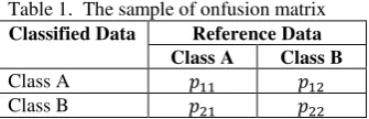
Confusion matrix is used to assess the quality of the results. This assessment can calculate how big the failure of cloud and cloud shadow detection is. In the confusion matrix, the diagonal elements represent the pixel correctly classified, while off-diagonal elements represent errors, either of commission or omission (Congalton, 1991).
Table 1. The sample of onfusion matrix
Classified Data Reference Data
Class A Class B
Class A
Class B
In confusion matrix, it is possible to derive two class specific indices i.e., Commission Error (CE) and Omission Error (OE). The formula of CE and OE as follows (Congalton and Green, 1999):
In confusion matrix, it is possible to derive two class specific indices i.e., CE and OE. The formula of CE and OE as follows (Congalton and Green, 1999):
(1)
(2)
where
= Commission Error
= Omission Error
= User’s Accuracy
= Producer’s Accuracy
The CE of a class A is the percentage of pixels classified as class A which does not belong to that class according to the reference data (commission). The OE is the percentage of the pixels, belonging to class A in the reference data, which have not been classified as such (omission). CE and OE make excellent candidate indices to represent the situation of reducing omission and commission errors as conflicting objectives.
3.5 Assessment using Comparison of Results
In order to prove the reliability of MCM, we will compare MCM with other methods of cloud masking. However, we
should have the software of the other methods if we want to run them and get some results. This is the main obstacle if we want to compare CSM and other methods, because most authors of the other methods do not publish their software to public.
Figure 8. 16-bit Landsat-8 QA Band (USGS)
Fortunately, Landsat-8 has a Landsat quality assessment band (QA band). This band can be used for cloud detection, cirrus detection, snow/ice detection, vegetation detection, etc. We can choose and take one or more of them for our purposes by isolating the range of the 16-bit Landsat-8 QA band. For example, we can isolate bit 14 to bit 15 for cloud detection. Afterwards, we can apply this result to the Landsat-8 image which has this band as well. The final result will be an cloud masking image.
4. RESULTS
The result of cloud masking can be seen in Figure 9. The cloud masking result shows that cloud can be identified correctly almost 100%. The MCM can distinguish between cloud and vegetation, cloud and settlement, and cloud and water bodies properly. The difficult part is to distinguish between cloud and settlement. However, MCM can address this issue correctly. We can see clearly that there is no settlement classified to be cloud.
(a) (b)
Figure 9. The result of cloud masking. Red colour indicates cloud region.
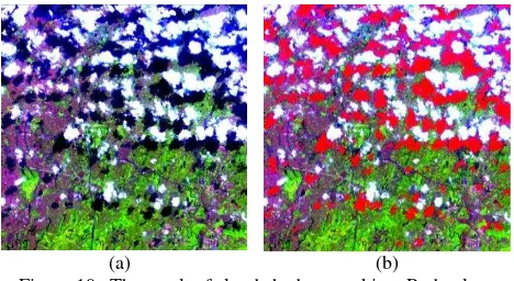
Figure 10 shows the result of cloud shadow masking. The cloud shadow masking result shows that cloud can be identified correctly almost 100%. The MCM can distinguish between cloud shadow and vegetation, cloud shadow and settlement, and cloud shadow and water bodies properly. The difficult part is to distinguish between cloud shadow and water bodies and MCM can address this issue correctly. It can be seen clearly that there are no water bodies classified to be cloud shadow.
(a) (b)
Figure 10. The result of cloud shadow masking. Red colour indicates cloud shadow region.
We compare MCM to another method to demonstrate the reliabilty of MCM. In this case, we apply cloud masking using QA band from Landsat-8. The result of cloud masking using QA band can be seen in Figure 12. Moreover, the detail of the result can be seen clearly in figure 13.
(a) (b)
Figure 11. The result of cloud masking using QA band. Red colour indicates cloud region.
MCM Original Image QA Band
(a) (b) (c)
(d) (e) (f)
Figure 12. The detail result of cloud masking using QA band. Red colour indicates cloud region.
We can see in Figure 13c that the large area of settlement is detected as cloud in the experiment using QA band. Moreover, several pixels of cloud fail to be detected as cloud as well. On the other hand, we can see in Figure 13a that all of cloud cover is detected using MCM, but a bit area of settlement is detected as cloud. In this case, we tend to reduce omission error to zero because we can use the result to produce cloud free image using mosaicking in a further work.
It can also be seen in Figure 13f that small area of cloud fails to be detected as cloud using QA band in vegetation area. On the
other hand, we can see that all of cloud area is detected as cloud using MCM.
In addition, the results of cloud detection using QA band are not smooth enough. We can see this in the border of the polygon of cloud regions. On the other hand, the border of the polygon of cloud regions in the MCM results is quite smooth.
Table 2. Confusion matrix of the cloud and cloud shadow masking using MCM algorithm
Classified Data Reference Data
Cloud Cloud
Shadow
Clear
Cloud 53750 173 601
Cloud Shadow 0 50995 863
Clear 140 2257 153365
Table 3. Commission error and omission error of cloud and cloud shadow masking using MCM algorithm
Cloud Masking Cloud Shadow
Masking
Commission Error 0.014 0.017
Omission Error 0.003 0.045
We can see in Table 3 that the commission error of cloud and cloud shadow masking using MCM algorithm is very small. It means that this algorithm has ability to avoid the wrong detection of cloud and cloud shadow. On the other hands, the omission error is very small as well. It means that the algorithm can detect cloud and cloud shadow very well.
5. DISCUSSION AND CONCLUSIONS
In this paper, we proposed MCM algorithm to detect cloud and cloud shadow in a tropical environment. This algorithm uses band 3, band 4 to distinguish between cloud and non-cloud region. Afterwards, band 5 and band 6 are used to distinguish between cloud shadow and clear region. The results show that MCM can detect cloud and cloud shadow properly and the accuracy is very high. However, we only detect thick cloud. Therefore, in the future, we plan to develop algorithm for cloud and cloud shadow masking using the image which has thick and thin cloud.
ACKNOWLEDGEMENTS
The authors would like to thank and appreciate the anonymous reviewers for their comments. The authors would also like to thank the U.S. Geological Survey (USGS) for providing Landsat-8 images as well.
REFERENCES
A. S. Arnesen, T. S. F. Silva, L. L. Hess, E. M. L. M. Novo, C. M. Rudoff, B. D. Chapman, K. C. McDonald., Monitoring flood extent in the lower Amazon River floodplain using ALOS/PALSAR ScanSAR images. Remote Sensing of Environment, Vol. 130, pp. 51–61.
C. R. Suribabu, J. Bhaskar, and T. R. Neelakantan., Land Use/Cover Change Detection of Tiruchirapalli City, India, Using Integrated Remote Sensing and GIS Tools. J Indian Society Remote Sensing 40(4), pp. 699–708.
C. Tang, J. Zhu, X. Qi, and J. Ding., 2013. Landslides induced by the Wenchuan earthquake and the subsequent strong rainfall The International Archives of the Photogrammetry, Remote Sensing and Spatial Information Sciences, Volume XLI-B2, 2016
event: A case study in the Beichuan area of China. using MCM algorithm, Vol. 122, pp. 22–33.
G. Berhan, S. Hill, T. Tadesse, and S. Atnafu., 2011. Using Satellite Images for Drought Monitoring: A Knowledge Discovery Approach. Journal of Strategic Innovation and Sustainability, Vol. 7(1).
J. J. Qu, A. M. Powell, Jr., M . V. K. Sivakumar., 2013. Satellite-based Applications on Climate Change. Springer Atmospheric Sciences.
J. Ju and D. P. Roy., 2008. The availability of cloud-free Landsat ETM Plus data over the conterminous United States and globally. Remote Sensing of Environmental. Vol. 112(3), pp. 1196–1211.
M. E. Hajj, A. Begue, B. Lafrance, O. Hagolle, G. Dedieu, M. Rumeau., 2008. Relative Radiometric Normalization and Atmospheric Correction of a SPOT 5 Time Series. Sensors, Vol. 8, pp. 2774-2791.
NASA, International Satellite Cloud Climatology Project, http://isccp.giss.nasa.gov/role.html, Accessed on 12 September 2015.
N. Demirel, S. Duzgun, and M. K. Emil., 2011. Landuse change detection in a surface coal mine area using multi-temporal high-resolution satellite images. International Journal of Mining, Reclamation and Environment, Vol. 25(4), pp. 342–349.
N. R. Godwin, L. J. Collett, R. J. Denham, N. Flood., 2013. Cloud and cloud shadow screening across Queensland, Australia: An automated method for Landsat TM/ETM+ time Series, Remote Sensing of Environment, 2013, Vol. 134, pp. 50-65.
O. Hagolle, M. Huc, D. V. Pascual, G. Dedieu., 2010. A multi-temporal method for cloud detection, applied to FORMOSAT-2, VENµS, LANDSAT and SENTINEL-2 images, Remote Sensing of Environment, Vol. 114, pp. 1747-1755.
R. G. Congalton., 1991. A review of assessing the accuracy of classifications of remotely sensed data, Remote Sensing of Environment, Vol. 37, pp. 35 – 46.
R.R. Irish., 2000. Landsat 7 Automatic Cloud Cover Assessment. Proceedings of SPIE, Vol. 4049, pp. 438-355.
R. R. Irish, J. L. Baker, S. N. Forward and T. Qrvidson., 2006. Characterization of the Landsat-7 ETM Automated Cloud-Cover Assessment (ACCA) Algorithm. Vol. 72, (10), pp. 1179– 1188.
S. E. Park, Y. Yamaguchi, and D. J. Kim., 2013. Polarimetric SAR remote sensing of the 2011 Tohoku earthquake using ALOS/PALSAR. Remote Sensing of Environment, Vol 132, pp. 212–220.
S. R. Proud, R. Fensholt, L. V. Rasmussen, I. Sandholt., Rapid response flood detection using the MSG geostationary satellite. International Journal of Applied Earth Observation and Geoinformation, Vol. 13(4), pp. 536–544.
Wang, B., Ono, A., Muramatsu, K. and Fujiwara, N., 1999. Automated detection and removal of cloud and their shadow
from Landsat TM images. IEICE Transactions on Information and Systems. Vol. E82-D, pp. 453-460.
X. Yang and L. Chen., 2010. Using multi-temporal remote sensor imagery to detect earthquake-triggered landslides. International Journal of Applied Earth Observation and Geoinformation, Vol 12, pp. 487–495.
X. Zhang, T. Kang, H. Wang, and Y. Sun., 2010. Analysis on spatial structure of landuse change based on remote sensing and geographical information system. Volume 12, Supplement 2, pp. S145–S150.
Y. Dong, Q. Li, A. Dou, and X. Wang., 2011. Extracting damages caused by the 2008 Ms 8.0 Wenchuan earthquake from SAR remote sensing data. Journal of Asian Earth Sciences Vol. 40, pp. 907–914.
Y. Song, J. B. Njoroge, and Y. Morimoto, 2013. Drought impact assessment from monitoring the seasonality of vegetation condition using long-term time-series satellite images: a case study of Mt. Kenya region. Environ Monit. Assess, Vol 185, pp. 4117–4124.
Z. Zhu, C. E. Woodcock., 2012. Object-based cloud and cloud shadow detection in Landsat imagery. Remote Sensing Environment, Vol. 118, pp. 83-94.
Z. Zhu, C. E. Woodcock., 2014. Automated cloud, cloud shadow, and snow detection in multitemporal Landsat data: An algorithm designed specifically for monitoring land cover change, Remote Sensing of Environment, Vol. 152, pp. 217-234.
Z. Zhu, S. Wang, C. E. Woodcock., 2015. Improvement and expension of the Fmask algorithm: cloud, cloud shadow, and snow detection for Landat 4-7, 8, and Sentinel 2 images, Remote Sensing and Environment, Vol. 159, pp. 269-277. The International Archives of the Photogrammetry, Remote Sensing and Spatial Information Sciences, Volume XLI-B2, 2016