PAPER • OPEN ACCESS
Analysis of tranverse reinforcement circular section of reinforced
concrete columnas the effect of flexure and axial load
To cite this article: W Kartini et al 2018 J. Phys.: Conf. Ser.953 012230
View the article online for updates and enhancements.
1
Content from this work may be used under the terms of theCreative Commons Attribution 3.0 licence. Any further distribution of this work must maintain attribution to the author(s) and the title of the work, journal citation and DOI.
Published under licence by IOP Publishing Ltd
Analysis of tranverse reinforcement circular section of
reinforced concrete column
as the effect of flexure and axial
load
W Kartini1, M D Astawa2, and A Fauzi3
1,2Civil Departement, Universitas Pembangunan Nasional “Veteran” Jawa Timur 3Civil Engineering Student, Universitas Pembangunan Nasional “Veteran” JawaTimur, Rungkut Madya Gunung Anyar, Surabaya, Indonesia
1[email protected], 2[email protected], 3[email protected]
Abstract. Column is a pressed element that enabels to withstand the loads for its structure. The analysis was conducted at the round reinforced column and tied rather than the spherical round reinforced column. The proportion of this column structure was designed in accordance with the fuction of a building and the zone area of the same earthquake, as well as its loading and dimension of the same space.Furthermore, the researcheralso did comparing the ductility’s score of reinforced concrete column of a building from wich a model of history building with its width of 20 m, length 30 m and height 40 m had been designed. Based on its proportion of inner force and column ductility and calculation result of ties spiral round space column it was obtained that the inner force of maximum axial (P) = 4356,6 kN, Shear2-2 (V2) = 132.3 kN, Moments 3-3 (M3 ) = 142.9 kNm and ductility = 4.59. Meanwhile, the ties rounded-space column was obtained that its axial maximum force was (P)=4169.8 kN, Shear2-2 (V2) = 131.3 kN, Moments 3-3 (M3) = 141.4 kNm and ductility 4, 11. Based on the analysis above, it was concluded which had ductility score greather than that of rounded-ties space with the same space (Ag).
1. Introduction
2
problems of this research was dealing with the behavior’s study of reinforced concrete column, such as the column behavior’s study receiving some buckling and ductility. The column used was the ties spiralconcrete and we only analizedthe comparison of ties variation.
2. Method
The column structural designed received the axial and flexure force and from requirement fulfilling of structural safety based on SNI 1727:2013, SNI 1726:2012, and SNI 2847:2013.
Column can be restrainted in efforts to increase its axial supporting power. Meanwhile, its nominal capacity of theoretical axial load of non-slender column is as follows:
0,80 φ 0,85. . . ...(1) While,
Ag = weidth of concrete gross
Ast = reinforcement extent of steel stretching fy= melting tension/stress of longitudinal steel f = reduction factor of FRP
f’cc = stressed force of restrainted concrete,psi ( MPa )
However, in efforts to increase ductility factor of column transfer, plastic transfer ductility had to be increased, this can be achieved by restraintment. Due to its deflection, curvator and rotation were equivalent with its moment, so that ductility factor was intended for the material can be written as follows: Ductility factor = andheight:40 m, so the column dimension design was made the same.
Wtotal = Wfloor+ Wroof
= 2190,8+ 118,08 = 2308,9 kN
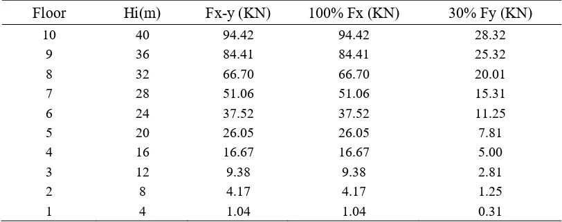
3.2 Earthqake Load
Earthquake load design of a building structure used the equivalent static load. Table 1.The Value of Earthquake Load of Each Story
Floor Hi(m) Fx-y (KN) 100% Fx (KN) 30% Fy (KN)
Source : Data of Research Result
3.3 Column Design
3
a. Quality of the Concrete (fc’) : 35 Mpa b. Quality of the BJ 37 Steel (fy) : 240 Mpa
c. Concrete decking : 40 mm
3.3.1 Determination of Round Column Dimension
Structure calculation using round column (ties) was carried out by re-calculating the structure of a bulding by changing the square columns as it was used previously into ties. The calculation itself was based on the ratio between square column and ties sectional area (Ag). It should be noted that both of the accounted cross-sectional area (Ag) are the same. The ties dimension calculation could be seen as the following calculation:
a. Dimension of Square column 56.5 Ag = 250591 mm2
From the graph of the column diagram can be obtined : r = 1,85 %
ρ = r . β = 0,018 x 1 = 0,018
Ast = ρ . Ag = 0,018 x 250591 = 4510,6 mm2
b. Calculation of Round Column Capacity (Ties)
According to SNI 2847: 2013 Article 10.3.6.2, the axial load capacity of the column should not be less than the axial load of the factored structure analysis.
Ag = 250591 mm2
To equate column transversal reinforcement (ties) with tiesspiral by (SNI 2847 – 2013 article 9.10) ties spiralnet distance should not exceed 75 mm andnot less than 25 mm. Then the distance of the ties uesd
for the rounded column is ties ∅10 – 75.
3.3.2 Ductility Calculation of Round Column (Ties)
From the curvature moment diagram of a tiesrounded column D56.5, the column’s ductility obtained was 4.111.
3.4 The Concept of Strong Column Weak Beam
In accordance with the philosophy of capacity design, SNI 2847-2013 Article 21.6.2 requires that:
1,2
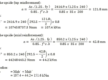
In order to find the value of Mg, the followings are the data needed for its calculation: a. Beam drag reinforcement 5D19 (As1 = 2416.9 mm2)
b. Beam tap reinforcement 3 D19 (As = 850.2 mm2) c. Sengkang (Ties) diameter 8 mm
d. Concrete cover taken 30 mm
e. d = 350 – 30 – 8 – 0.5 x 19 = 292.5 mm
The value of Mnb was obtained by adding upMnb+ and Mnb- of the beams which were integrated with the column. In this case, the equation is as the following:
4
ΣMnc value obtained from the column interaction diagram using PCAcoloumn is Mnc = 305 kN.m Requirements of Strong Column Weak Beam (SNI 2847 – 2013 Article 21.6.2)
305 kNm 1.2 (151.6) = 181.9 …………. OK
3.5 Calculation of Statistical Analysis Using SAP2000
Based on the calculation result of inner force resulted from D56.5, spherical ties round column is as follows:
Table 2. Inner Force Result analyzed and Round Column D56.5Analysis
Column Pu (kN) V2 (kN) M3 (kNm)
Round (Tied) 4169.9 131.3 141.4
Round (Spiral) 4239.8 132.8 142.8
Source: Research Data
3.6 The Comparison of Column Capacity
The comparison between round (ties) column capacity and round (spiral) column capacity could be seen in Table 3 below:
5
1. From the calculation result of roundedcolumnties spiral, it had a relatively greater force behavior compared with the roundedcolumn ties from which it was obtained that its maximum axial force (P) = 4169.8 kN, shear 2-2 (V2) = 131.3 kN, shear3-3 (V3) = 40.7 kN, moment 2-2 (M2) = 88.7 kNm, and moment 3-3 (M3) = 141.4 kNm;
2. Regarding with the reinforcement designof transversal column in accordance with SNI 2847:2013, that was the round tiesspiral column, it was found that the clear distance between ties spiral should not either more than 75 mm orless than 25 mm. Then it was obtained that the comparison of column ductilitythe rounded column tiesspiral ductility was 4.592 and the roundedcolumn ties ductility was 4.111.
3. Finally, based on the analysis result, it could be concluded that transversal reinforcement affected to the strength of column’s structure. Therefore, the distancebetween the ties reinforcement of reinforced concrete column, the greater strength thatcolumn structure was. Thus, the round ties spiral concrete column had a greater ductility value compared with the tiesone.
5. Acknowledgments
The authors would like thank to Coordinator of Civil Engineering Program and Faculty of Engineeringwhich gives opportunity to author can participate in this seminar.
6. References
[1] Andika Eko Praseto, Estyningtyas Puspita Alfiany, Re-Design Building Structure D University Muhammadiyah II Candi-Sidoarjo by Method Medium Moment Bearer Frame System,Surabaya,
2008.
[2] Wira Apriyanto, Comparison of Buckling Column Using Structured Steel Profiles and
Composites, University of Northern Sumatera: Medan, 2007.
[3] Badan Standardisasi Nasional, Earthquake Resistance Design Procedures for Building Structures, BSN: Bandung, (SNI 03-1726-2002).
[4] Badan Standardisasi Nasional, Design Procedures for Concrete Structures for Buildings, (SNI
03-2847-2002).
[5] Departemen Pekerjaan Umum, Peraturan Pembebanan Indonesia Untuk Bangunan Gedung
(PPIUG), 1983.
[6] Istimawan Dipohusodo, Reinforced Concrete Structures, PT. Gramedia Pustaka Utama, Jakarta,
1994.
[7] M. Lukman Farisi, Comparison Efficiency of Round and Square Column Materials on Four-story Building Structures,University of Jember: Jember, 2012.
[8] Imran, Iswandi and Ediansjah Zulkifli, Basic Design of Reinforced Concrete Stuctures, Bandung:
Penerbit ITB, 2014.
[9] Jack C McCormac, Reinforced Concrete Design Fifth Edition Volume 1,Erlangga, Jakarta, 2004.
[10] Muhammad Amitaba Pattisia, Study of the Behavior of Columns due to Axial and Bending Forces (beam-columns) by Using Abaqus 6.7 in Earthquake Zone,Surabaya, ITS.
[12] Rahmat Purwono, Design of Earthquake Resistant Reinforced Concrete Structure, Jakarta,
2005.
[13] Ryan Setyawan, Ductility of Reinforced Concrete Frames on the Tower Building BMKG Juanda Surabaya,University of Pembangunan National “Veteran” East Java Surabaya,2014.