Axial Compressive Behavior of Square Concrete Columns Externally
Collared by Light Structural Steel Angle Sections
Pamuda Pudjisuryadi
Department of Civil Engineering,
Sepuluh Nopember Institute of Technology (ITS), Surabaya, Indonesia. Department of Civil Engineering, Petra Christian University, Surabaya, Indonesia.
Tavio
Department of Civil Engineering,
SepuluhNopember Institute of Technology (ITS), Surabaya, Indonesia.
Priyo Suprobo
Department of Civil Engineering,
SepuluhNopember Institute of Technology (ITS), Surabaya, Indonesia.
Abstract
The buildings which were designed and built in the past according to the old seismic code or no seismic code at all urgently require a retrofitting effort to satisfy the current seismic and building codes. To demolish and rebuild them would be very costly than to retrofit. Some of the available seismic retrofitting techniques are the concrete jacketing, steel jacketing, external strand pre-stressing, Fiber Reinforced Polymer (FRP) jacketing, and steel collar jacketing. In this study, a new steel collar is proposed as an alternative of seismic retrofitting techniques of existing buildings. The primary objective of the study is to propose an economical, efficient, effective, and practical method for retrofitting the square or even rectangular RC columns. Light structural steel angle sections have been introduced for collar elements. These collars will be installed externally at the perimeter of RC column sections to enhance their strengths and ductilities. To achieve this objective, a set of experimental work was carried out to investigate the effectiveness of the proposed technique in retrofitting the existing RC column specimens. Eight column specimens were casted and tested under monotonic compressive load with or without the collars in order to investigate the performance of the proposed retrofitting method. The volumetric ratio of steel collar elements is set as a main parameter in the study. Three control specimens were only confined with conventional stirrups for comparison. The remaining specimens were just confined with the external steel collars. The test results indicate that the proposed external retrofitting technique works well for confinement method. Significant strength and ductility gains are observed in the study. The proposed external steel collars as an alternative of retrofitting techniques for existing columns can be concluded to be very promising.
Keywords: compressive strength, ductility, external confinement, retrofit, square concrete columns, steel collars, stress-strain curves.
Introduction
In the past, the urgency of designing seismic-resistant buildings was not mandatory. If a seismic code provided the seismic map was available at the time, the designed seismic load produced according to the code was lower than that obtained by the current seismic code. This is due to the lack of knowledge on seismic risk in the past that has not been well assessed and studied. Most of the existing buildings were designed according to the old seismic code or even no seismic code at all in the old time. They are currently required urgently to be enhanced in terms of strength and performance. The later has gained so much attention to be the basis of the nowadays seismic design concept which does not require the strength anymore but the ductility. Thus, buildings which were designed and built in the past in accordance with the old seismic code or no seismic code urgently require a retrofitting effort to satisfy the current seismic and building codes. The main reason is that they do not have enough strength or ductility as per the latest seismic and building codes. To demolish and rebuild them would be very costly than to retrofit. The word of retrofitting has been increasingly popular than strengthening since highly likely to meet the current seismic and building code provisions the ductility aspect would govern over the strength. The strength in a ductile seismic building structure is no longer a primary concern anymore just like in the old time or when it is under gravity load.
literatures [1-36]. With development of the knowledge about seismic action, typically newer codes specify higher demand. One implication of this fact is the needs of upgrading many existing structures, including Reinforced Concrete (RC) structures. According to Liu et al. [8], the resulting deficiencies that often characterize old existing RC frame structures include: (1) insufficient transverse reinforcement to confine the column core and to restrain buckling of longitudinal reinforcement; (2) inadequate lap splices located immediately above floor levels where inelastic actions may be concentrated with large flexural demand; (3) insufficient shear strength to develop the column flexural capacity, or the potential degradation of column shear strength with increasing flexural ductility demand; (4) inadequate column strength to develop a strong-column weak-beam mechanism, and (5) deficient beam-to-column joint dimensions and details. For most framed structures, it is more economical to design for dissipating seismic energy in a flexural mode by forming plastic ductile hinges in beams rather than in columns [9]. However, columns are critical elements in any structural building system and their performance during a seismic event can dominate the overall performance of the structure since single column failure can lead to additional failures and potentially result in total building collapse [8]. Mander et al. [2, 3] mentioned that the most important issue in plastic hinge design of reinforced concrete columns is the availability of sufficient transverse reinforcement for confining the concrete, preventing the buckling of longitudinal reinforcement, and avoiding brittle shear failure. In order to provide such requirement on existing deficient RC columns, retrofitting should be introduced.
One of the commonly used retrofitting approaches of RC columns is by improving the confinement. The most conventional method is by installing the additional reinforcement embedded in the concrete jacketing. The more recent methods are by externally introducing the use of confinement layer or elements since they are considered easier and faster to implement as a retrofitting techniques to the existing buildings. Among this approaches are the steel sheet jacketing [10-13], fiber-reinforced polymer (FRP) composite jacketing [14-17], and steel collar jacketing [8, 18-23]. Ideally, an effective retrofitting technique shall possess such characteristics as being easy to implement, minimizing disruption to the use of the structure, not requiring highly specialized skills, minimizing labor costs, and resulting in efficient performance [8]. Concrete and steel jacket are very effective but inconvenient to install, because doing so requires using scaffolds for curing the concrete or grout [13]. FRP jackets have several advantages over the steel and concrete jackets: (1) ease of installation; (2) no increment of the cross section; and (3) no increment of the flexural or shear stiffness of the structure. However the price of FRP jackets is generally higher than that of concrete and steel jackets [13]. Driver et al. [8, 18-19] developed retrofitting technique by using steel collars cut from solid steel plates or Hollow Square Sections (HSS) which are installed by using high strength bolts or
welding. The method has been proven to be effective. Pudjisuryadi et al. [20, 21], Pudjisuryadi and Tavio [22], and Tavio et al. [23] reported their early analytical as well as experimental works on the investigations of the effects of external steel collars on square concrete columns. The confinement elements used were a set of light structural steel angle section collars, installed by fastening the corner bolts without the application of any grouts. This paper further discusses the performance of the retrofitting method in order to provide a better understanding.
Experimental Setup
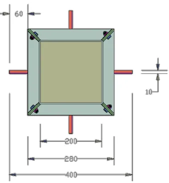
A set of column specimens collared by light structural angle steel sections was tested to study their behaviors under axial compression and to confirm that the proposed technique is a very potential and promising option for retrofitting square or possibly rectangular RC columns, particularly when the confinement requirement is not satisfied or provided. The cross sectional dimensions and height of the specimens were 200 200 600 mm, respectively. The specimens were divided into 400-mm middle test region and two 100-mm strengthened regions at both ends. The clear concrete cover was 20-mm thick. The strengthened regions were better confined than the test region such that no failure was possible to occur in these regions. The square concrete columns were then confined externally by a set of light structural steel angle section collars. The angle sectional dimensions were 40 40
Figure 1: Typical Perspective View of Test Specimen (Specimen S03 as an Illustration)
Figure 2: Typical Exploded View of Test Specimen (Specimen S03 as an Illustration)
Figure 3: Typical Layout Plan View of Test Specimen
Figure 4: Typical Elevation View of Test Specimen (Specimen S03 as an Illustration)
Figure 5: Monotonic Compressive Loading Test Setup
STRONG FLOOR LVDT STEEL PLATE
Figure 6: Four Load Cells with 50 Tons Capacity Placed Below Test Specimen
Figure 7: Typical Test Setup (S04 is Shown)
Specimen Design
Three control specimens were made, namely CS01, CS02a, and CS03a. These control specimens are intended to study the behavior of conventionally confined column specimens under compressive load. CS01 is constructed without any confinement within the test region, and only 4-D10 longitudinal reinforcements are used. CS02a is designed to represent the condition of columns confined without seismic provisions. The confinement requirements according to Indonesian concrete code are as follows:
Avmin =
75√fc'
1200
bw. s fyh ≥
1 3
bw. s
fy (1)
where:
Avmin = minimum area of stirrups, bw = width of concrete element, 𝑓𝑐′ = concrete strength,
s = spacing of stirrups,
fyh = yield strength of stirrups steel.
This requirement should be accompanied with maximum shear spacing, which is the smallest of these expressions:
a) 16 times the diameter of longitudinal reinforcement (160mm)
b) 48 times the diameter of transverse reinforcement (480mm)
c) the smaller dimensions of the column (200mm)
Due to test region length restriction, a confinement of D10-133 mm is selected (Av/s = 1.18 mm2/mm, and volumetric ratio = 0.89 percent). The volumetric ratio is defined as the volume of confining steel with respect to the volume of concrete. It should be noted that normally the volume of concrete for calculating volumetric ratio is the confined concrete core. But, since the confined concrete sectional area is different in the case of internal (inside core) and external confinement (gross area) , either should be picked for the sake of comparison. In this paper, the volume of concrete for calculating the volumetric ratio is determined from the gross cross-sectional area of the column multiplied by the spacing of the confining steel in the mid-test region. Specimen CS03a is designed to represent the condition of columns confined with seismic confinement requirement. The seismic confinement requirements according to Indonesian concrete code are as follows:
Avmin1 = 0.09(s. hc. fc '
fyh) (2)
Avmin2 = 0.3(s. hc. fc '
fyh) ( Ag
Ach-1) (3)
where:
hc = cross sectional dimension of member core Ag = gross area of concrete section
Ach = cross sectional area of member core
This requirement must be accompanied with maximum shear spacing specified by Indonesian concrete code, which is the smallest value of these following expressions:
a) one quarter of smallest dimensions of column b) six times the diameter of longitudinal bars c) 100+(350 –hx)/3 < 150mm
d) 100mm
where hx is the maximum center-to-center distance of supported longitudinal bars. Reinforcing confinement of D10-50 is chosen for this specimens (Av/s = 3.14 mm2/mm, and volumetric ratio = 2.36 percent). Illustration of Specimens CS01, CS02a, and CS03a can be seen in Figure 8. Since the axial loading is concentric, all sides of column specimens should suffer the same strains (stresses). However, in order to capture the unexpected eccentricity or other imperfection of the specimens, several strain gauges are attached to longitudinal and stirrups inside the specimens.
specimens are named S01, S02, S03, S04, and S05. Without any internal confinement steel in the test region, these five specimens were built to study the basic effect of proposed confinement technique on square concrete columns. The resulting volumetric ratios of these five specimens range from 3.84 to 11.51 percent. Illustration of these five specimens can be seen in Figure 9 to Figure 13. Besides the longitudinal bars inside, several strain gages are also attached on the steel collars. Table 1 summarizes the details of reinforcement and confinement of the test specimens.
Figure 8: Control Specimens CS01, CS02a, and CS03a
Figure 9: Test Specimens S01
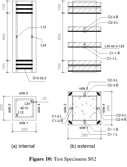
Figure 10: Test Specimens S02
Figure 11: Test Specimens S03
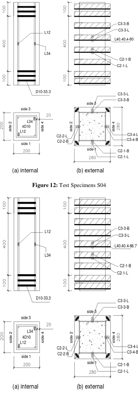
Figure 12: Test Specimens S04
Figure 13: Test Specimen S05
Table 1: Details of Test Specimen’s Reinforcement
and Confinement
Results and Discussions of Monotonic Compressive
Load Test
The mechanical properties of the concrete used in the test specimens were obtained from standard cylinders made from the same mix proportion. The average strength (fc′) of totally 11 cylinders is 23.93 MPa with a standard deviation of 2.01 MPa. Tensile tests were carried out to obtain the mechanical properties of steel bars and steel angle sections. The average yield strength (fy) of deformed bars (with nominal diameter of 9.5 mm) used in the test specimens is 317 MPa with a standard deviation of 5.9 MPa obtained from three bar samples. Tensile test of a strip steel plate, cut from the steel angle section, indicated that the average yield strength (fysc) is 285 MPa. Monotonic compressive load tests of all specimens were conducted with controlled axial displacement, and the axial resistances of the columns were recorded. The tests were stopped if one of the following criteria was found: (1) failure of specimen; (2) resistance drops below 50 percent of the peak strength; or (3) limitation of LVDT capacity.
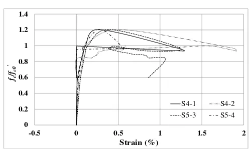
Strength and Ductility Improvement
Two of the main interests by providing confinement on concrete columns are the strength and ductility improvement. In order observe those, a normalized axial stress-strain curves are presented (see Figure 14). From control Specimen CS01, it is found that the concrete strength is equal to 17.02 MPa (fc0' ). This strength is used to normalize the stress-strain curve in order to investigate the effect of confinement of other specimens. The peak strain (𝜀01) and ultimate strain (𝜀cu′ = 𝜀f50) of Specimen CS01 are equal to 0.23 percent and 1.37 percent, respectively. In this paper, the strain corresponding with 50 percent of peak strength on the descending branch of the curve is defined as the ultimate strain. To identify the ductility of axially loaded specimens, the commonly used parameter is the relative strain ductility ratio (με= εf85⁄ε01). εf85 is defined as the strain corresponding with 85 percent of peak strength on the descending branch. The numerical data result of all specimens is listed in Table 2.
The strength gain can directly be indicated by the normalized peak strengths of Specimens. CS02a which was conventionally confined with deficient volumetric ratio, showed no strength gain (0.95). The control Specimen CS03a
C3-3-B
Label Long Bars Confinement Elements
CS01 4 D10 None
CS02a 4 D10 D10-133 (vol. ratio = 0.89%) CS03a 4 D10 D10-50 (vol. ratio = 2.36%)
showed strength gain of 1.21 due to its good confinement. The very brittle behavior, that the strength decreased rapidly after reaching the peak strength (με = 1.63 and 3.27 respectively). S01 showed rather similar behavior, except that it had late post-peak ductility response (με = 2.30). CS03a showed good ductility (με = 15.55) until it finally lose the strength at about 10.90 percent axial strain. Collared specimens with higher volumetric ratio, better ductility pattern is observed except for specimen S04 which suffered early steel collar failure. Specimens S02, S03, and S05 indicated με of 4.84, 8.15, and 26.16 respectively, while S04 only showed με of 3.46. In term of ductility, the proposed retrofitting method has demonstrated that it can provide comparable value as the conventionally confined Specimen CS03a which was built according to seismic provisions.
Figure 14: Normalized Axial Stress vs. Strain of Test Specimens
Table 2: Summary of Monotonic Compression Tests
Parameter CS01 CS02a Cs03a S01 S02 S03 S04 S05
Pcmax = maximum resistance contributed by concrete
cc = axial strain corresponding to 𝑃𝑐𝑚𝑎𝑥
fcc' = confined concrete strength
fc0' = concrete strength of unconfined specimen (CS01)
Failure Mechanism of the Specimens
From the strain measurement, it is evident that the stirrups, as well as the steel collars acted as confinement element. While the longitudinal bars were in compression, the stirrups and steel collars were in tension during the test. Typical strain from the longitudinal bars (shown for Specimen CS01) can be seen in Figure 15. The typical strain in the stirrups (shown for Specimen CS03a) can be seen in Figure 16. Typical strain in steel collar (shown for collar 3 of Specimen S05) can be seen in Figure 17. The images of the damaged Specimens CS01, CS02a, and CS03a after the tests can be seen in Figure 18. It is obvious that the absence of any confinement (CS01) caused brittle diagonal failure in the specimen. Arbitrary crack initiation would progress rapidly which lead to sudden failure of this unconfined specimen. Specimen CS02a which was poorly confined also suffered brittle failure, but the damage was not as severe as CS01. Specimen CS03a which is confined conventionally by stirrups required by seismic provisions could prevent the core from severe brittle failure. Buckling of longitudinal bars was observed, but it should be noted that it happened at a very large axial strain (the test was stopped at axial strain more than 10 percent).
Figure 15: Normalized Axial Stress vs. Strain of Longitudinal Bars (CS01)
Figure 17: Normalized Axial Stress vs. Strain of Collar 3 (S05)
(a) (b) (c)
Figure 18: Damaged Specimens: (a) CS01, (b) CS02a, and (c) CS03a
The concrete damages of collared specimens after the tests can be seen in Figure 19 and Figure 20. The lightest confined Specimen S01 showed brittle diagonal failure (see Figure 19(a)). It is evident that the steel collar did not fully utilize its function as confinement element that only small deformation was observed (see Figure 21). Damage patterns in Specimen S02 clearly showed the confinement effect of the steel collars that severe concrete damages occurred in regions in between the collars (see Figure 19(b)). But still, the concrete failure occurred prior to full confining potential of the collars (again, the collars showed slight deformations as seen in Figure 22). In Specimen S03, the brittle failure is completely avoided. The specimen could still maintain half of its peak axial capacity at a very large axial strain of 8.97 percent. It can be seen in Figure 19(c) that the specimen was severely damaged (spall of concrete and buckling of longitudinal bars). But the fact that it still has good resistance showed that the confinement worked and protected the inner core. Out of the three collars installed (see Figure 23 and Figure 24), the one at the middle of the test region (collar 2) worked most optimally that it experienced the most deformation.
(a) (b) (c)
Figure 19: Damaged Specimens: (a) S01, (b) S02, and (c) S03
(a) (b)
Figure 20: Damaged Specimens: (a) S04, and (b) S05
Figure 21: Damaged Collar 1 (S01)
Unfortunately, S04 failed to show the expected performance. Due to imperfection of workmanship in preparing the collar, welding at one of the corner suffered early failure (Figure 25). Severe concrete damage was observed at the level of failed steel collar (Figure 20a).
0 0.2 0.4 0.6 0.8 1 1.2 1.4 1.6
-0.2 0 0.2 0.4 0.6 0.8 1 1.2
fc
/fc0
'
Strain (%)
C3-3-L C3-3-B
Specimen S05 showed very good performance as expected. The post peak behavior show minor degradation up to large axial strain of about 8 percent. At this point, one collar failed and some concrete damage occurred. But since it still can maintain about 50 percent of its peak capacity, the test was continued. The specimen finally lost its resistance when the second collars failed at axial strain almost as large as 12 percent. The failed steel collars are shown in Figure 26. Important notes on the observation of the specimen damages are summarized in Table 3.
(a) (b)
Figure 22: Damaged Collars: (a)1; and (b)2 of S02
(a) (b)
Figure 23: Damaged Collars: (a)1; and (b)2 of S03
Figure 24: Damaged Collar 3 (S03)
Figure 25: Welding Failure of Collar 3 (S04)
(a) (b)
Figure 26: Damaged of Two Failed Collars: (a)2; and (b) 3 of S05
Table 3: Important Notes on Experimental Tests of Column Specimens
Specimen fcc’/fc0’ Remark (descending branch)
CS01 1
Strength loss after descending to 60% of peak strength (at strain 0.62%). Brittle diagonal failure and buckling of longitudinal bars were observed.
CS02a 0.954
Test was stopped after descending branch dropped below 50% of peak strength at strain about 1.5%. Excessive damages and buckling of longitudinal bars were observed.
CS03a 1.206
Test was stopped at 50% peak strength (strain 10.90%), coinciding with LVDT limitation. Still can resist axial force, but buckling of longitudinal bars was observed.
Strength dropped below 50% at strain about 1.2 %. Brittle diagonal failure and buckling of longitudinal bars were observed.
S02 1.325
Strength dropped below 50% peak strength at strain about 3.5%. Buckling of longitudinal bars was observed.
S03 1.209
Strength dropped below 50% peak strength at strain about 7.4%. Buckling of longitudinal bars was observed.
S04 1.232
Strength dropped below 50% peak strength at strain about 3.8%. Failure of collar 3 and buckling of longitudinal bars were observed.
S05 1.422
Two strength drops at 76% of peak strength (strain 8.15%), and at 46% of peak strength (strain 11.64%) due to broken collars 2 and 3 respectively. Buckling of longitudinal bars was also observed.
Concluding Remarks
As alternative of the already available retrofitting method, an external confining technique of square concrete columns is proposed. The method uses a set of steel angle collars as external confinement on square concrete columns. Some advantages of the proposed method are better constructability by introducing economic light structural steel angle sections which only involves minor cutting and welding processes, and has higher applicability by only mounting up the collars on the four faces of the column without any grouting and then fasten the structural bolts at its four corners. An experimental work has been conducted to validate the reliability of the proposed technique. From the test results, some conclusions can be made as follows:
Improved axial stress-strain behavior was achieved by specimens externally confined by the proposed method as compared to the plain concrete control specimen (CS01).
Specimens with smaller amount of steel collars suffered brittle failure, but ductile behaviors were observed in specimens with larger amount of steel collars. It also should be noted that specimens with small amount of confinement were more likely to experience un-symmetric failure (diagonal crack seen in S01). In the case of S01, symmetric resistance (measured from lvdt reading on each side of specimen) was only observed up to 80 percent of ascending branch. From that point, damage started leading to unsymmetric resistance of the specimen.
From damaged patterns observation, it is clear that the steel collars work as confining element. Strips of concrete regions confined by the steel collars show less damaged regions in between the steel collars.
Behavior of control specimen CS03a with 2.36 percent volumetric ratio of internal confining element, is matched by steel collared specimens S03 (with 7.68 percent volumetric ratio of confining 11.34 percent volumetric ratio of confining element) can reach peak strength of 1.422 times of CS01 strength, and show f50 more than 10.00 percent.
The failures of steel collars were often located in the corners. Improvement of corner plates and welding works were encouraged for better performance of the steel angle collars as external confinement element.
References
[1] Sheikh, S. A., “A Comparative Study on Confinement Models, ” ACI Journal, V. 79, No. 4, July-Aug. 1982, American Concrete Institute, Farmington Hills, Michigan, USA, pp. 296-306. [2] Mander, J. B.;Priestley, M. J. N.; and Park, R.,
“Theoretical Stress-Strain Model for Confined
Concrete, ” Journal of Structural Engineering, ASCE, V. 114, No. 8, Aug. 1988, American Society of Civil Engineers, Reston, Virginia, USA, pp. 1824-1826.
[3] Mander, J. B.;Priestley, M. J. N.; and Park, R.,
“Observed Stress-Strain Behavior of Confined Concrete, ” Journal of Structural Engineering, ASCE, V. 114, No. 8, Aug. 1988, American Society of Civil Engineers, Reston, Virginia, USA, pp. 1827-1849. Strength Concrete Confined by Welded Wire Fabric,
” Journal of Materials in Civil Engineering, ASCE, V. 19, No. 4, Apr. 2007, American Society of Civil Engineers, Reston, Virginia, USA, pp. 286-294. [6] Hoshikusuma, J.; Kawashima, K.; Nagaya, K.; and American Society of Civil Engineers, Reston, Virginia, USA, pp. 281-289.
[8] Liu J.; Driver R. G.; and Lubell, A. S.,
“Rehabilitation and Repair of Reinforced Concrete Short Columns with External Steel Collars, ” Structural Engineering Report No. 281, Department of Civil & Environmental Engineering, University of Alberta, Canada, Oct. 2008, 303 pp.
[9] Sheikh, S. A; and Yeh, C. C., “Flexural Behavior of Confined Concrete Columns, ” ACI Journal, May-June 1986, pp. 389-404.
[10] Chai, Y. H.;Priestley, M. J. N.; and Seible, F.,
“Analytical Model for Steel-Jacketed RC Circular Bridge Columns, ” Journal of Structural Engineering, ASCE, V. 120, No. 8, Aug. 1994, American Society of Civil Engineers, Reston, Virginia, USA, pp. 2358-2376.
[11] Priestley, M. J. N.; Seible, F.; Xiao, Y.; andVerma, R., “Steel Jacket Retrofitting of Reinforced Concrete Bridge Columns for Enhanced Shear Strength–Part 2: Test Results and Comparison with Theory, ” ACI Structural Journal, V. 91, No. 5, Sep.-Oct. 1994, pp. 537-551.
[12] Xiao, Y.; and Wu, H., “Retrofit of Reinforced Concrete Columns using Partially Stiffened Steel Jackets, ” Journal of Structural Engineering, ASCE, V. 129, No. 6, June 2003, American Society of Civil Engineers, Reston, Virginia, USA, pp. 725-732. [13] Choi, E.; Chung, Y. S.; Park, J.; and Cho, B. S.,
Structural Journal, V. 107, No. 6, Nov.-Dec. 2010, pp. 654-662.
[14] Saafi, M.; Toutanji, H. A.; and Li, Z., “Behavior of Concrete Columns Confined with Fiber-Reinforced Polymer Tubes, ” ACI Material Journal, V. 96, No. 4, July-Aug. 1999, American Concrete Institute, Farmington Hills, Michigan, USA, pp. 500-509. [15] Fam, A. Z.; and Rizkalla, S. H., “Confinement Model
for Axially Loaded Concrete Confined by Circular Fiber-Reinforced Polymer Tubes, ” ACI Structural Journal, V. 98, No. 4, July-Aug. 2001, American Concrete Institute, Farmington Hills, Michigan, USA, pp. 541-461.
[16] Carey, S. A.; and Harries, K. A., “Axial Behavior and Modeling of Confined Small-, Medium-, and Large-Scale Circular Sections with Carbon Fiber-Reinforced Polymer Jackets, ” ACI Structural Journal, V. 102, No. 4, July-Aug. 2005, American Concrete Institute, Farmington Hills, Michigan, USA, pp. 596-604.
[17] Lee, C. S.; Hegemier, G. A.; and Phillippi, D. J.,
“Analytical Model for Fiber-Reinforced Polymer-Jacketed Square Concrete Columns in Axial Compression, ” ACI Structural Journal, V. 107, No. 2, Mar.-Apr. 2010, American Concrete Institute, Farmington Hills, Michigan, USA, pp. 208-217. [18] Hussain, M. A.; and Driver, R. G., “Experimental
Investigation of External Confinement of Reinforced Concrete Columns by Hollow Structural Section Collars, ” ACI Structural Journal, V. 102, No. 2, Mar.-Apr. 2005, American Concrete Institute, Farmington Hills, Michigan, USA, pp. 242-251. [19] Chapman J. R.; and Driver R. G., “Behaviour of
Collared Concrete Columns under Concentric and Eccentric Loads, ” Structural Engineering Report 263, Department of Civil & Environmental Engineering, University of Alberta, Canada, Jan. 2006, 140pp.
[20] Pudjisuryadi, P.; Tavio; and Suprobo, P., “Analytical Confining Model of Square Reinforced Concrete
Columns using External Steel Collars”, International Journal of ICT-aided Architectural and Civil Engineering, Australia, V. 1, No. 1, June 2014, pp. 1-18.
[21] Pudjisuryadi, P.; Tavio; and Suprobo, P., “Transverse Stress Distribution in Concrete Columns Externally Confined by Steel Angle Collars, ” The 2nd International Conference on Earthquake Engineering and Disaster Mitigation (ICEEDM-II), 19-20 July 2011, Shangri-La Hotel, Surabaya, Indonesia, pp. H-139-H-143.
[22] Pudjisuryadi, P.; and Tavio, “Compressive Strength Prediction of Square Concrete Columns Retrofitted with External Steel Collars, ” Civil Engineering Dimension: Journal of Civil Engineering Science and Application, Thomson GaleTM, Petra Christian
University, Surabaya, Indonesia, V. 15, No. 1, Mar. 2013, pp. 18-24.
[23] Tavio; Pudjisuryadi, P.; Suprobo, P., “L-Shaped Steel Collars: An Alternative External Confining
Retrofit for Improving Ductility and Strength of
Rectangular Concrete Columns”, Proceedings: International Seminar on Concrete Technology: Green Concrete Technology Innovation, 3-4 June 2013, Semarang, Indonesia, pp. 36-50.
[24] Kusuma, B.; and Tavio, “Unified Stress-Strain Model for Confined Columns of Any Concrete and Steel Strengths, ” The 1stInternational Conference on Earthquake Engineering and Disaster Mitigation, 14-15 Apr. 2008, Jakarta, Indonesia, pp. 502-509. [25] Kusuma, B.; and Tavio, “A Comparative Study of
Models for Confinement of Concrete by Welded Wire Mesh, ” The 1stInternational Conference Rehabilitation and Maintenance in Civil Engineering (ICRMCE), 21-22 Mar. 2009, SebelasMaret University, Solo, Indonesia, pp. 90-101.
[26] Kusuma, B.; Tavio; and Suprobo, P., “Axial Load Behavior of Concrete Columns with Welded Wire Fabrics as Transverse Reinforcement, ” The Twelfth East Asia-Pacific Conference on Structural Engineering & Construction (EASEC-12), 26-28 Jan. 2011, Hong Kong Convention and Exhibition Center, Hong Kong, Procedia Engineering, Elsevier Ltd., V. 14, Paper No. 256, pp. 2039-2047.
[27] Kusuma, B.; Tavio; and Suprobo, P., “Prediction of Peak Stress for Concrete Confined with Welded Wire Fabric, ” The 2ndInternational Conference on Earthquake Engineering and Disaster Mitigation (ICEEDM-II), 19-20 July 2011, Shangri-La Hotel, Surabaya, Indonesia, pp. F-117-F-131.
[28] Tavio; Budiantara, I N.; and Kusuma, B., “Spline Nonparametric Regression Analysis of Stress-Strain Curve of Confined Concrete, ” Civil Engineering Dimension: Journal of Civil Engineering Science and Application, Thomson GaleTM, Petra Christian
University, V. 10, No. 1, Mar. 2008, Surabaya, Indonesia, pp. 14-27.
[29] Tavio; and Kusuma, B., “Stress-Strain Model for High-Strength Concrete Confined by Welded Wire Fabric, ” Discussion, Journal of Materials in Civil Engineering, ASCE, V. 21, No. 1, Jan. 2009, American Society of Civil Engineers, Reston, Virginia, USA, pp. 40-45.
[30] Tavio; Kusuma, B.; and Suprobo, P., “Experimental Behavior of Concrete Columns Confined by Welded Wire Fabric as Transverse Reinforcement under Axial Compression, ” ACI Structural Journal, V. 109, No. 3, May-June 2012, American Concrete Institute, Farmington Hills, Michigan, USA, pp. 339-348.
[31] Tavio; Suprobo, P.; and Kusuma, B., “Effects of Grid Configuration on the Strength and Ductility of HSC Columns Confined with Welded Wire Fabric under Axial Loading, ” The 1stInternational Conference on Modern, Construction and Maintenance of Structures, V. 1, 10-11 Dec. 2007, Hanoi, Vietnam, pp. 178-185.
Conference Excellence in Concrete Construction – through Innovation, 9-10 Sept. 2008, Kingston University, London, UK, pp. 339-344.
[33] Tavio; Suprobo, P.; and Kusuma, B., “Strength and Ductility Enhancement of Reinforced HSC Columns Confined with High-Strength Transverse Steel, ” The Eleventh East Asia-Pacific Conference on Structural Engineering & Construction (EASEC-11), 19-21 Nov. 2008, Taipei International Convention Center, Taipei, Taiwan, pp. 350-351.
[34] Tavio; Suprobo, P.; and Kusuma, B., “Investigation of Stress-Strain Models for Confinement of Concrete by Welded Wire Fabric, ” The Twelfth East Asia-Pacific Conference on Structural Engineering & Construction (EASEC-12), 26-28 January 2011, Hong Kong Convention and Exhibition Center, Hong Kong, Procedia Engineering, Elsevier Ltd., V. 14, Paper No. 255, pp. 2031-2038.
[35] Tavio; and Tata, A., “Predicting Nonlinear Behavior and Stress-Strain Relationship of Rectangular Confined Reinforced Concrete Columns with ANSYS, ” Civil Engineering Dimension: Journal of Civil Engineering Science and Application, Thomson GaleTM, Petra Christian University, V. 11, No. 1,
Mar. 2009, Surabaya, Indonesia, pp. 23-31.
[36] Tavio; Wimbadi, I.; Negara, A. K.; and Tirtajaya R.,
“Effects of Confinement on Interaction Diagrams of
Square Reinforced Concrete Columns, ” Civil Engineering Dimension: Journal of Civil Engineering Science and Application, Thomson GaleTM, Petra Christian University, Surabaya,