FOUNDATION
ENGINEERING
HANDBOOK
Design and Construction with the
2009 International Building Code
Robert W. Day
Principal Engineer American GeotechnicalSan Diego, California
Second Edition
New York Chicago San Francisco Lisbon London Madrid Mexico City Milan New Delhi San Juan Seoul
Copyright © 2010, 2006 by The McGraw-Hill Companies, Inc. All rights reserved. Except as permitted under the United States Copyright Act of 1976, no part of this publication may be reproduced or distributed in any form or by any means, or stored in a database or retrieval system, without the prior written permission of the publisher.
ISBN: 978-0-07-174010-4
MHID: 0-07-174010-4
The material in this eBook also appears in the print version of this title: ISBN: 978-0-07-174009-8,
MHID: 0-07-174009-0.
All trademarks are trademarks of their respective owners. Rather than put a trademark symbol after every occurrence of a trademarked name, we use names in an editorial fashion only, and to the benefi t of the trademark owner, with no intention of infringement of the trademark. Where such designations appear in this book, they have been printed with initial caps.
McGraw-Hill eBooks are available at special quantity discounts to use as premiums and sales promotions, or for use in corporate training programs. To contact a representative please e-mail us at [email protected].
Information contained in this work has been obtained by The McGraw-Hill Companies, Inc. (“McGraw-Hill”) from sources believed to be reliable. However, neither McGraw-Hill nor its authors guarantee the accuracy or completeness of any information published herein, and neither McGraw-Hill nor its authors shall be responsible for any errors, omissions, or damages arising out of use of this information. This work is published with the understanding that McGraw-Hill and its authors are supplying information but are not attempting to render engineering or other professional services. If such services are required, the assistance of an appropriate professional should be sought.
TERMS OF USE
This is a copyrighted work and The McGraw-Hill Companies, Inc. (“McGrawHill”) and its licensors reserve all rights in and to the work. Use of this work is subject to these terms. Except as permitted under the Copyright Act of 1976 and the right to store and retrieve one copy of the work, you may not decompile, disassemble, reverse engineer, reproduce, modify, create derivative works based upon, transmit, distribute, disseminate, sell, publish or sublicense the work or any part of it without McGraw-Hill’s prior consent. You may use the work for your own noncommercial and personal use; any other use of the work is strictly prohibited. Your right to use the work may be terminated if you fail to comply with these terms.
For more information on individual and institutional subscriptions, please visit www.accessengineeringlibrary.com
ACCESS
Engineering
Authoritative content Immediate solutions
g
AccessEngineering of
ehensive coverage and compr
fast title-by-title access to our engineering collection in the fast title-by-title access to our engineering collection in the
In addition, sophisticated personalization tools allow content to
terms is included in a fully sear
In addition, sophisticated personalization tools allow content to terms is included in a fully sear
In addition, sophisticated personalization tools allow content to
"
e information on individual and in e information on individual and in
v
CONTENTS
Preface xi
Acknowledgments xiii
Chapter 1. Introduction 1.1
1.1. Definitions / 1.1
1.2. Project Requirements / 1.3
1.3. Preliminary Information and Planning the Work / 1.4
1.4. Engineering Geologist / 1.5
1.5. Outline of Chapters / 1.7
Part 1 Geotechnical Engineering
Chapter 2. Subsurface Exploration 2.3
2.1. Introduction / 2.3
2.2. Document Review / 2.3
2.3. Purpose of Subsurface Exploration / 2.7
2.4. Borings / 2.9
2.5. Test Pits and Trenches / 2.49
2.6. Preparation of Logs / 2.51
2.7. Geophysical Techniques / 2.55
2.8. Geotechnical Earthquake Engineering / 2.61
2.9. Subsoil Profile / 2.65
Notation / 2.66
Problems / 2.69
Chapter 3. Laboratory Testing 3.1
3.1. Introduction / 3.1
3.2. Index Tests / 3.2
3.3. Oedometer Test / 3.16
3.4. Shear Strength of Cohesionless Soil / 3.19
3.5. Shear Strength of Cohesive Soil / 3.29
3.6. Laboratory Compaction Tests / 3.65
3.7. Permeability Tests / 3.77
Notation / 3.81
Problems / 3.84
Chapter 4. Soil Mechanics 4.1
4.1. Introduction / 4.1
4.2. Soil Classification / 4.1
4.4. Effective Stress / 4.21
4.5. Stress Distribution / 4.24
4.6. Total Stress and Effective Stress Analyses / 4.41
4.7. Permeability and Seepage / 4.57
Notation / 4.72
Problems / 4.74
Part 2 Foundation Design
Chapter 5. Shallow and Deep Foundations 5.3
5.1. Introduction / 5.3
5.2. Selection of Foundation Type / 5.3
5.3. Shallow Foundations / 5.4
5.4. Deep Foundations / 5.6
Problems / 5.17
Chapter 6. Bearing Capacity of Foundations 6.1
6.1. Introduction / 6.1
6.2. Bearing Capacity for Shallow Foundations / 6.5
6.3. Bearing Capacity for Deep Foundations / 6.16
6.4. Lateral Load Capacity of Deep Foundations / 6.31
6.5. Geotechnical Earthquake Engineering / 6.41
Notation / 6.49
Problems / 6.51
Chapter 7. Settlement of Foundations 7.1
7.1. Introduction / 7.1
7.2. Collapsible Soil / 7.2
7.3. Settlement of Cohesionless Soil / 7.9
7.4. Other Common Causes of Settlement / 7.27
7.5. Foundations on Rock / 7.34
7.6. Allowable Settlement / 7.40
Notation / 7.46
Problems / 7.47
Chapter 8. Consolidation 8.1
8.1. Introduction / 8.1
8.2. Laboratory Consolidation Test / 8.3
8.3. Immediate Settlement / 8.11
8.4. Primary Consolidation / 8.16
8.5. Rate of Primary Consolidation / 8.24
8.6. Secondary Compression / 8.33
8.7. Consolidation of Soil beneath Shallow Foundations / 8.34
8.8. Consolidation of Soil beneath Deep Foundations / 8.38
8.9. Settlement of Unsaturated Cohesive Soil / 8.41
Notation / 8.45
Chapter 9. Foundations on Expansive Soil 9.1
9.1. Introduction / 9.1
9.2. Expansion Potential / 9.2
9.3. Basic Expansive Soil Principles / 9.17
9.4. Methods Used to Predict Foundation Movement / 9.30
9.5. Foundation Design for Expansive Soil / 9.41
9.6. Flatwork / 9.47
9.7. Expansive Rock / 9.49
Notations / 9.50
Problems / 9.52
Chapter 10. Slope Stability 10.1
10.1. Introduction / 10.1
10.2. Rockfall / 10.5
10.3. Surficial Slope Stability / 10.10
10.4. Gross Slope Stability / 10.18
10.5. Landslides / 10.32
10.6. Debris Flow / 10.47
10.7. Slope Softening and Creep / 10.50
Notations / 10.56
Problems / 10.57
Chapter 11. Retaining Walls 11.1
11.1. Introduction / 11.1
11.2. Simple Retaining Wall without Wall Friction / 11.3
11.3. Simple Retaining Wall with Wall Friction / 11.7
11.4. Design and Construction of Retaining Walls / 11.13
11.5. Restrained Retaining Walls / 11.17
11.6. Mechanically Stabilized Earth Retaining Walls / 11.20
11.7. Sheet Pile Walls / 11.25
11.8. Temporary Retaining Walls / 11.31
11.9. Moisture Migration through Basement Walls / 11.37
Notation / 11.41
Problems / 11.43
Chapter 12. Foundation Deterioration and Cracking 12.1
12.1. Introduction / 12.1
12.2. Timber Decay / 12.1
12.3. Sulfate Attack of Concrete / 12.3
12.4. Frost / 12.7
12.5. Historic Structures / 12.8
12.6. Shrinkage Cracking / 12.13
12.7. Moisture Migration through Slab-on-Grade Foundations / 12.18
Chapter 13. Geotechnical Earthquake Engineering for Soils 13.1
13.1. Introduction / 13.1
13.2. Basic Earthquake Principles / 13.2
13.3. Peak Ground Acceleration / 13.13
13.4. Liquefaction / 13.19
13.5. Slope Stability / 13.31
Notation / 13.45
Problems / 13.46
Chapter 14. Geotechnical Earthquake Engineering for Foundations
and Retaining Walls 14.1
14.1. Introduction / 14.1
14.2. Earthquake Structural Damage / 14.2
14.3. Foundation Settlement / 14.9
14.4. Retaining Walls / 14.20
14.5. Foundation Alternatives to Mitigate Earthquake Effects / 14.31
Notation / 14.34
Problems / 14.35
Part 3 Foundation Construction
Chapter 15. Grading and Other Soil Improvement Methods 15.3
15.1. Grading / 15.3
15.2. Compaction / 15.14
15.3. Soil Improvement Methods / 15.22
Notation / 15.27
Problems / 15.27
Chapter 16. Foundation Excavation, Underpinning, and Field Load Tests 16.1
16.1. Introduction / 16.1
16.2. Foundation Excavation and Construction / 16.2
16.3. Field Load Tests / 16.28
16.4. Foundation Underpinning / 16.32
16.5. Observational Method / 16.40
Chapter 17. Geosynthetics and Instrumentation 17.1
17.1. Introduction / 17.1
17.2. Geosynthetics / 17.1
17.3. Instrumentation / 17.7
Part 4 2009 International Building Code
Chapter 18. International Building Code Regulations for Soils 18.3
18.1. Introduction / 18.3
18.2. Soils Investigation / 18.5
18.3. Excavation, Grading, and Fill / 18.7
18.4. Presumptive Load-Bearing Values of Soils / 18.10
CONTENTS ix
Chapter 19. International Building Code Regulations for Foundations 19.1
19.1. Introduction / 19.1
19.2. General Regulations for Footings and Foundations / 19.1
19.3. Foundations Adjacent Slopes / 19.2
19.4. Retaining Walls / 19.4
19.5. Geotechnical Earthquake Engineering / 19.6
Appendix A. Glossary A.1
A.1. Subsurface Exploration Terminology / A.4
A.2. Laboratory Testing Terminology / A.10
A.3. Terminology for Engineering Analysis and Computations / A.16
A.4. Compaction, Grading, and Construction Terminolgy / A.21
A.5. Geotechnical Earthquake Engineering Terminolgy / A.28
Bibliography / A.34
Appendix B. Example of a Foundation Engineering Report B.1
B.1. Introduction / B.1
B.2. Site Observations / B.1
B.3. Geology / B.4
B.4. Site Investigation / B.6
B.5. Conclusions / B.6
B.6. Foundation Recommendations / B.6
B.7. Other Considerations / B.8
B.8. Closure / B.8
Appendix C. Solutions to Problems C.1
Appendix D. Conversion Factors D.1
Appendix E. Bibliography E.1
xi
PREFACE
The goal of the book is to present the practical aspects of geotechnical and foundation engineering. While the major emphasis of college education is engineering analyses, this often represents only a portion of the knowledge needed to practice geotechnical engineering. One objective of this book is to discuss the engineering judgment that needs to be acquired through experience. An example is the application of sufficient redundancy in the design and construction of the project.
In California, structural engineers typically perform the actual structural design of the foundation based on the recommendations supplied by the geotechnical engineer. Foundation design, in terms of determining the type and spacing of steel reinforcement in concrete footings, is not covered in this textbook. This book deals only with the geotechnical aspects of foundation engineering. In addition, this book is only applicable for the analyses of clean soil, which does not contain any known or sus-pected hazardous materials. Such environmental issues are outside the scope of this book.
Because of the assumptions and uncertainties associated with geotechnical engineering, it is often described as an “art,” rather than an exact science. Thus simple analyses are prominent in this book, with complex and theoretical evaluations kept to an essential minimum. For most projects, a limited number of borings or test pits are used to investigate the soil and geologic makeup of a site. Hence, except for cases where the site consists of solid rock, there will usually be uncertainty in the final analyses. Because of this, when dealing with foundations bearing on soil, it is always best to take a conservative approach.
Part 1 (Chapters 2 to 4) deals with basic geotechnical field and laboratory studies, such as subsur-face exploration and laboratory testing of soil, rock, or groundwater samples. Part 2 (Chapters 5 to 14) presents the geotechnical aspects of foundation engineering, including the conditions commonly encountered by the design engineer, such as settlement, expansive soil, and slope stability. Part 3 (Chapters 15 to 17) provides a discussion of the performance or engineering evaluation of foundation construction, and Part 4 (Chapters 18 and 19) consists of concluding chapters dealing with the appli-cation of the building code for foundation engineering.
The book presents the practical aspects of geotechnical and foundation engineering. The topics should be of interest to design engineers, especially Part 4 that deals with the International Building Code. In this second edition, Part 4 has been revised to be in conformance with the 2009 International Building Code. The remainder of the book is essentially unchanged from the first edi-tion.
xiii
ACKNOWLEDGMENTS
I am grateful for the contributions of the many people who helped to make this book possible. Special thanks are due to the American Society of Civil Engineers (ASCE) and the International Code Council (ICC), who jointly sponsored this work. The continued support of Mark Johnson at ICC is greatly appreciated as well as the effort of Hamid Naderi at ICC for his review and comments concerning Chapters 18 and 19.
Portions of this book are reproduced from Geotechnical and Foundation Engineering: Design and Constructionand I would like to thank Professor Charles C. Ladd, at the Massachusetts Institute of Technology, who reviewed that text and offered many helpful suggestions. I would also like to thank Professor Ladd for the opportunity to have worked on his Orinoco clay project. Several figures, especially those in the section on shear strength, are reproduced from my M.I.T. thesis (Engineering Properties of the Orinoco Clay). In addition, I would like to thank Dr. Ladd for the opportunity to have worked with him on various projects over the years.
Numerous practicing engineers provided valuable assistance during the development of the text. In particular, I am indebted to Tom Marsh, principal engineer at American Geotechnical, who provided extensive technical support and assistance. The contributions of my fellow engineers, including Robert Brown, Eric Lind, Rick Walsh, and Scott Thoeny, are also appreciated. Thanks also to Dennis Poland, Ralph Jeffery, and Todd Page for their help with the geologic aspects of the book, and Rick Dorrah for drafting various figures for the book.
For contributions to the chapter on laboratory testing, I would like to thank Professor Timothy Stark, at the University of Illinois, who performed the ring shear tests, provided a discussion of the test procedures and the photographs, and prepared the ring shear test plots. Thanks also to Kean Tan, principal of Kean Tan Laboratories, who performed the triaxial compression tests and provided the photographs. I also appreciate the help of Sam Mahdavi, laboratory manager at American Geotechnical, who provided the direct shear test results and photographs.
For contributions to the sections on geotechnical earthquake engineering, I would like to thank Professor Nelson, who provided Figure 13.22 and additional data concerning the Turnagain Heights landslide. The help of Thomas Blake, who provided assistance in the use and understanding of his computer programs, is also appreciated.
I would also like to thank Gregory Axten, president of American Geotechnical, who provided valuable support during the review and preparation of the book. Thanks also to Carl Bonura and John Pizzi for their longtime friendship and technical inputs.
Tables and figures taken from other sources are acknowledged where they occur in the text. Finally, I wish to especially thank Larry Hager at McGraw-Hill who has always supported my work and had the patience to see my books completed. Thanks also to Pamela Pelton, David Fogarty, and others in McGraw-Hill.
CHAPTER 1
INTRODUCTION
1.1 DEFINITIONS
A foundation is defined as that part of the structure that supports the weight of the structure and transmits the load to underlying soil or rock. In general, foundation engineering applies the knowl-edge of geology, soil mechanics, rock mechanics, and structural engineering to the design and con-struction of foundations for buildings and other structures. The most basic aspect of foundation engineering deals with the selection of the type of foundation, such as using a shallow or deep foun-dation system. Another important aspect of founfoun-dation engineering involves the development of design parameters, such as the bearing capacity or estimated settlement of the foundation. Foundation engineering could also include the actual foundation design, such as determining the type and spac-ing of steel reinforcement in concrete footspac-ings. Foundation engineerspac-ing often involves both geot-echnical and structural engineers, with the geotgeot-echnical engineer providing the foundation design parameters such as the allowable bearing pressure and the structural engineer performing the actual foundation design.
Foundations are commonly divided into two categories: shallow and deep foundations. Table 1.1 presents a list of common types of foundations. In terms of geotechnical aspects, foundation engi-neering often includes the following (Day, 1999a, 2000a):
• Determining the type of foundation for the structure, including the depth and dimensions • Calculating the potential settlement of the foundation
• Determining design parameters for the foundation, such as the bearing capacity and allowable soil bearing pressure
• Determining the expansion potential of a site
• Investigating the stability of slopes and their effect on adjacent foundations
• Investigating the possibility of foundation movement due to seismic forces, which would also include the possibility of liquefaction
• Performing studies and tests to determine the potential for deterioration of the foundation • Evaluating possible soil treatment to increase the foundation bearing capacity
• Determining design parameters for retaining wall foundations
• Providing recommendations for dewatering and drainage of excavations needed for the construc-tion of the foundaconstruc-tion
• Investigating groundwater and seepage problems and developing mitigation measures during foun-dation construction
• Site preparation, including compaction specifications and density testing during grading • Underpinning and field testing of foundations
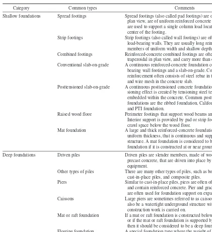
TABLE 1.1 Common Types of Foundations
Category Common types Comments
Shallow foundations Spread footings Spread footings (also called pad footings) are often square in plan view, are of uniform reinforced concrete thickness, and are used to support a single column load located directly in the center of the footing.
Strip footings Strip footings (also called wall footings) are often used for load-bearing walls. They are usually long reinforced concrete members of uniform width and shallow depth.
Combined footings Reinforced-concrete combined footings are often rectangular or trapezoidal in plan view, and carry more than one column load. Conventional slab-on-grade A continuous reinforced-concrete foundation consisting of
bearing wall footings and a slab-on-grade. Concrete reinforcement often consists of steel rebar in the footings and wire mesh in the concrete slab.
Posttensioned slab-on-grade A continuous posttensioned concrete foundation. The postten-sioning effect is created by tenpostten-sioning steel tendons or cables embedded within the concrete. Common posttensioned foundations are the ribbed foundation, California slab, and PTI foundation.
Raised wood floor Perimeter footings that support wood beams and a floor system. Interior support is provided by pad or strip footings. There is a crawl space below the wood floor.
Mat foundation A large and thick reinforced-concrete foundation, often of uniform thickness, that is continuous and supports the entire structure. A mat foundation is considered to be a shallow foundation if it is constructed at or near ground surface.
Deep foundations Driven piles Driven piles are slender members, made of wood, steel, or precast concrete, that are driven into place by pile-driving equipment.
Other types of piles There are many other types of piles, such as bored piles, cast-in-place piles, and composite piles.
Piers Similar to cast-in-place piles, piers are often of large diameter and contain reinforced concrete. Pier and grade beam support are often used for foundation support on expansive soil. Caissons Large piers are sometimes referred to as caissons. A caisson can
also be a watertight underground structure within which construction work is carried on.
Mat or raft foundation If a mat or raft foundation is constructed below ground surface or if the mat or raft foundation is supported by piles or piers, then it should be considered to be a deep foundation system. Floating foundation A special foundation type where the weight of the structure is
balanced by the removal of soil and construction of an underground basement.
Basement-type foundation A common foundation for houses and other buildings in frost-prone areas. The foundation consists of perimeter footings and basement walls that support a wood floor system. The basement floor is usually a concrete slab.
1.2 PROJECT REQUIREMENTS
For some projects, the foundation design requirements will be quite specific and may even be in writ-ing. For example, a public works project may require a geotechnical investigation consisting of a cer-tain number, type, and depth of borings, and may also specify the types of laboratory tests to be performed. The more common situation is where the client is relying on the geotechnical engineer to prepare a proposal, perform an investigation, and provide foundation design parameters that satisfy the needs of the project engineers and requirements of the local building officials or governing authority. The general requirements for foundation engineering projects are as follows (Tomlinson, 1986):
1. Knowledge of the general topography of the site as it affects foundation design and construc-tion, e.g., surface configuraconstruc-tion, adjacent property, the presence of watercourses, ponds, hedges, trees, rock outcrops, and the available access for construction vehicles and materials
2. The location of buried utilities such as electric power and telephone cables, water mains, and sewers 3. The general geology of the area with particular reference to the main geologic formations
under-lying the site and the possibility of subsidence from mineral extraction or other causes 4. The previous history and use of the site including information on any defects or failures of
exist-ing or former buildexist-ings attributable to foundation conditions
5. Any special features such as the possibility of earthquakes or climate factors such as flooding, seasonal swelling and shrinkage, permafrost, or soil erosion
6. The availability and quality of local construction materials such as concrete aggregates, build-ing and road stone, and water for construction purposes
7. For maritime or river structures, information on tidal ranges and river levels, velocity of tidal and river currents, and other hydrographic and meteorological data
8. A detailed record of the soil and rock strata and groundwater conditions within the zones affected by foundation bearing pressures and construction operations, or of any deeper strata affecting the site conditions in any way
9. Results of laboratory tests on soil and rock samples appropriate to the particular foundation design or construction problems
10. Results of chemical analyses on soil or groundwater to determine possible deleterious effects of foundation structures
Often the client lacks knowledge of the exact requirements of the geotechnical aspects of the pro-ject. For example, the client may only have a vague idea that the building needs a foundation, and therefore a geotechnical engineer must be hired. The owner assumes that you will perform an inves-tigation and prepare a report that satisfies all of the foundation requirements of the project.
Knowing the requirements of the local building department or governing authority is essential. For example, the building department may require that specific items be addressed by the geotech-nical engineer, such as settlement potential of the structure, grading recommendations, geologic aspects, and for hillside projects, slope stability analyses. Examples of problem conditions requiring special consideration are presented in Table 1.2. Even if these items will not directly impact the pro-ject, they may nevertheless need to be investigated and discussed in the geotechnical report.
There may be other important project requirements that the client is unaware of and is relying on the geotechnical engineer to furnish. For example, the foundation could be impacted by geologic hazards, such as faults and deposits of liquefaction prone soil. The geotechnical engineer will need to address these types of geologic hazards that could impact the site.
In summary, it is essential that the geotechnical engineer know the general requirements for the project (such as the 10 items listed earlier) as well as local building department or other regulatory requirements. If all required items are not investigated or addressed in the foundation engineering report, then the building department or regulatory authority may refuse to issue a building permit. This will naturally result in an upset client because of the additional work that is required, delays in construction, and possible unanticipated design and construction expenses.
1.3 PRELIMINARY INFORMATION
AND PLANNING THE WORK
The first step in a foundation investigation is to obtain preliminary information, such as the following:
1. Project location. Basic information on the location of the project is required. The location of the project can be compared with known geologic hazards, such as active faults, landslides, or deposits of liquefaction prone sand.
2. Type of project. The geotechnical engineer could be involved with all types of foundation engi-neering construction projects, such as residential, commercial, or public works projects. It is important to obtain as much preliminary information about the project as possible. Such informa-tion could include the type of structure and use, size of the structure including the number of sto-ries, type of construction and floor systems, preliminary foundation type (if known), and estimated structural loadings. Preliminary plans may even have been developed that show the proposed construction.
3. Scope of work. At the beginning of the foundation investigation, the scope of work must be determined. For example, the scope of work could include subsurface exploration and laboratory
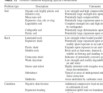
TABLE 1.2 Problem Conditions Requiring Special Consideration
Problem type Description Comments
Soil Organic soil, highly plastic soil Low strength and high compressibility
Sensitive clay Potentially large strength loss upon large straining Micaceous soil Potentially high compressibility
Expansive clay, silt, or slag Potentially large expansion upon wetting
Liquefiable soil Complete strength loss and high deformations caused by earthquakes
Collapsible soil Potentially large deformations upon wetting Pyritic soil Potentially large expansion upon oxidation
Rock Laminated rock Low strength when loaded parallel to bedding
Expansive shale Potentially large expansion upon wetting; degrades readily upon exposure to air and water
Pyritic shale Expands upon exposure to air and water
Soluble rock Rock such as limestone, limerock, and gypsum that is soluble in flowing and standing water
Cretaceous shale Indicator of potentially corrosive groundwater Weak claystone Low strength and readily degradable upon exposure to
air and water
Gneiss and schist Highly distorted with irregular weathering profiles and steep discontinuities
Subsidence Typical in areas of underground mining or high ground-water extraction
Sinkholes Areas underlain by carbonate rock (karst topography)
Condition Negative skin friction Additional compressive load on deep foundations due to settlement of soil
Expansion loading Additional uplift load on foundation due to swelling of soil
Corrosive environment Acid mine drainage and degradation of soil and rock Frost and permafrost Typical in northern climates
Capillary water Rise in water level which leads to strength loss for silts and fine sands
testing to determine the feasibility of the project, the preparation of foundation design parame-ters, and compaction testing during the grading of the site in order to prepare the building pad for foundation construction.
After the preliminary information is obtained, the next step is to plan the foundation investiga-tion work. For a minor project, the planning effort may be minimal. But for large-scale projects, the plan can be quite extensive and could change as the design and construction progresses. The plan-ning effort could include the following:
• Budget and scheduling considerations
• Selection of the interdisciplinary team (such as geotechnical engineer, engineering geologist, structural engineer, hydrogeologist and the like) that will work on the project
• Preliminary subsurface exploration plan, such as the number, location, and depth of borings • Document collection
• Laboratory testing requirements
• Types of engineering analyses that will be required for the design of the foundation
1.4 ENGINEERING GEOLOGIST
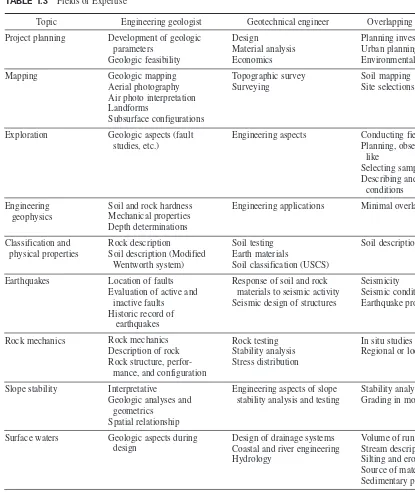
An engineering geologist is defined as an individual who applies geologic data, principles, and inter-pretation so that geologic factors affecting planning, design, construction, and maintenance of civil engineering works are properly recognized and utilized (Geologist and Geophysicist Act, 1986). In some areas of the United States, there may be minimal involvement of engineering geologists except for projects involving such items as rock slopes or earthquake fault studies. In other areas of the country, such as California, the geotechnical engineer and engineering geologist usually performs the geotechnical investigations jointly. The majority of geotechnical reports include both engineer-ing and geologic aspects of the project and both the geotechnical engineer and engineerengineer-ing geologist both sign the report. For example, a geotechnical engineering report will usually include an opinion by the geotechnical engineer and engineering geologist on the engineering and geologic adequacy of the site for the proposed development.
Table 1.3 (adapted fromFields of Expertise, undated) presents a summary of the fields of exper-tise for the engineering geologist and geotechnical engineer, with the last column indicating the areas of overlapping expertise. Note in Table 1.3 that the engineering geologist should have considerable involvement with foundations on rock, field explorations (such as subsurface exploration and surface mapping), groundwater studies, earthquake analysis, and engineering geophysics. Since geologic processes form natural soil deposits, the input of an engineering geologist can be invaluable for nearly all types of foundation engineering projects.
Because the geotechnical engineer and engineering geologist work as a team on most projects, it is important to have an understanding of each individual’s area of responsibility. The area of respon-sibility is based on education and training. According to the Fields of Expertise(undated), the indi-vidual responsibilities are as follows:
Responsibilities of the Engineering Geologist
1. Description of the geologic environment pertaining to the engineering project
2. Description of earth materials, such as their distribution and general physical and chemical char-acteristics
3. Deduction of the history of pertinent events affecting the earth materials 4. Forecast of future events and conditions that may develop
5. Recommendation of materials for representative sampling and testing
TABLE 1.3 Fields of Expertise
Topic Engineering geologist Geotechnical engineer Overlapping areas of expertise
Project planning
6. Recommendation of ways of handling and treating various earth materials and processes 7. Recommendation or providing criteria for excavation (particularly angle of cut slopes) in
materi-als where engineering testing is inappropriate or where geologic elements control stability 8. Inspection during construction to confirm conditions
Responsibilities of the Geotechnical Engineer
1. Directing and coordinating the team efforts where engineering is a predominant factor 2. Controlling the project in terms of time and money requirements and degree of safety desired 3. Engineering testing and analysis
4. Reviewing and evaluating data, conclusions, and recommendations of the team members 5. Deciding on optimum procedures
6. Developing designs consistent with data and recommendations of team members 7. Inspection during construction to assure compliance
8. Making final judgments on economy and safety matters
1.5 OUTLINE OF CHAPTERS
The purpose of this book is to present the geotechnical aspects of foundation engineering. The actual design of the foundation, such as determining the number and size of steel reinforcement for foot-ings, which is usually performed by the project structural engineer, will not be covered.
The book is divided into four separate parts. Part 1 (Chaps. 2 to 4) deals with the basic geotechni-cal engineering work as applied to foundation engineering, such as subsurface exploration, laboratory testing, and soil mechanics. Part 2 (Chaps. 5 to 14) presents the analysis of geotechnical data and engi-neering computations needed for the design of foundations, such as allowable bearing capacity, expected settlement, expansive soil, and seismic analyses. Part 3 (Chaps. 15 to 17) provides information for con-struction-related topics in foundation engineering, such as grading, excavation, underpinning, and field load tests. The final part of the book (Part 4, Chaps. 18 and 19) deals with the International Building Codeprovisions as applicable to the geotechnical aspects of foundation engineering.
Like most professions, geotechnical engineering has its own terminology with special words and definitions. App. A presents a glossary, which is divided into five separate sections:
1. Subsurface exploration terminology 2. Laboratory testing terminology
3. Terminology for engineering analysis and computations 4. Compaction, grading, and construction terminology 5. Geotechnical earthquake engineering terminology
Also included in the appendices are example of a foundation engineering report (App. B), solutions to the problems provided at the end of each chapter (App. C), and conversion factors (App. D).
A list of symbols is provided at the end of the chapters. An attempt has been made to select those symbols most frequently listed in standard textbooks and used in practice. Dual units are used throughout the book, consisting of:
1. Inch-pound units (I-P units), which are also frequently referred to as the United States Customary System units (USCS)
2. International System of Units (SI)
In some cases, figures have been reproduced that use the old metric system (stress in kg/cm2). These figures have not been revised to reflect SI units.
GEOTECHNICAL
ENGINEERING
2.3
CHAPTER 2
SUBSURFACE EXPLORATION
2.1 INTRODUCTION
As discussed in Chap. 1, the first step in the foundation investigation is to obtain preliminary infor-mation on the project and to plan the work. The next step is typically to perform the subsurface exploration. The goal of the subsurface investigation is to obtain a detailed understanding of the engi-neering and geologic properties of the soil and rock strata and groundwater conditions that could impact the foundation.
Specific items that will be discussed in the chapter are as follows:
1. Document review (Sec. 2.2)
2. Purpose of subsurface exploration (Sec. 2.3)
3. Borings (Sec. 2.4), including a discussion of soil samplers, sample disturbance, field tests, boring layout, and depth of subsurface exploration
4. Test pits and trenches (Sec. 2.5) 5. Preparation of logs (Sec. 2.6) 6. Geophysical techniques (Sec. 2.7)
7. Subsurface exploration for geotechnical earthquake engineering (Sec. 2.8) 8. Subsoil profile (Sec. 2.9)
2.2 DOCUMENT REVIEW
Prior to performing the subsurface exploration, it may be necessary to perform a document review. Examples of the types of documents that may need to be reviewed are as follows:
Prior Development. If the site had prior development, it is important to obtain information on the history of the site. The site could contain old deposits of fill, abandoned septic systems and leach fields, buried storage tanks, seepage pits, cisterns, mining shafts, tunnels, and other man-made sur-face and subsursur-face works that could impact the new proposed development. There may also be information concerning on-site utilities and underground pipelines, which may need to be capped or rerouted around the project.
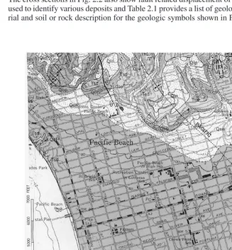
FIGURE 2.1 Geologic map. (From Kennedy, 1975.)
land surface is provided. This view may reveal important geologic information at the site, such as the presence of landslides, fault scarps, types of landforms (e.g., dunes, alluvial fans, glacial deposits such as moraines and eskers), erosional features, general type and approximate thickness of vegeta-tion, and drainage patterns. By comparing older versus newer aerial photographs, the engineering geologist can also observe any man-made or natural changes that have occurred at the site.
SUBSURFACE EXPLORATION 2.5
TABLE 2.1 Symbols and Descriptions for Geologic Map and Cross Sections Shown in Fig. 2.1 and 2.2
Geologic symbol Type of material Description
Qaf Artificial fill Artificial fill consists of compacted earth materials derived from many sources. Only large areas having artificial fill have been delineated on the geologic map.
Qb Beach sand Sand deposited along the shoreline derived from many sources
as a result of longshore drift and alluvial discharge from major stream courses.
Qal Alluvium Soil deposited by flowing water, including sediments deposited in river beds, canyons, flood plains, lakes, fans at the foot of slopes, and estuaries.
Qsw Slope wash Soil and/or rock material that has been transported down a slope
by mass wasting assisted by runoff of water not confined to channels.
Qls Landslide Landslides are mass movement of soil or rock that involves shear displacement along one or several rupture surfaces, which are either visible or may be reasonably inferred.
Qbp,Qlb,Qln Formational rock Various sedimentary rock formations formed during the
Pleistocene epoch (part of the Quaternary Period).
Ta,Tf,Tsc, Formational rock Various sedimentary rock formations formed during the Eocene
Tsd,Tst epoch (part of the Tertiary Period).
Kcs,Kp Formational rock Various rock formations formed during the Cretaceous Period.
Note: For geologic symbols, Qrepresents soil or rock deposited during the Quaternary Period, T=Tertiary Period, and K= Cretaceous Period.
FIGURE 2.3 Topographic map. (From USGS, 1975.)
A major source for geologic maps in the United States is the United States Geological Survey (USGS). The USGS prepares many different geologic maps, books, and charts and these documents can be purchased at the online USGS bookstore. The USGS also provides an “Index to Geologic Mapping in the United States,” which shows a map of each state and indicates the areas where a geo-logic map has been published.
Topographic Maps. Both old and recent topographic maps can provide valuable site information. Figure 2.3 presents a portion of the topographic map for the Encinitas Quadrangle, California (USGS, 1975). As shown in Fig. 2.3, the topographic map is to scale and shows the locations of buildings, roads, freeways, train tracks, and other civil engineering works as well as natural features such as canyons, rivers, lagoons, sea cliffs, and beaches. The topographic map in Fig. 2.3 even shows the locations of sewage disposal ponds, water tanks, and by using different colors and shading, it indicates older versus newer development. But the main purpose of the topographic map is to indi-cate ground surface elevations or elevations of the sea floor, such as shown in Fig. 2.3. This infor-mation can be used to determine the major topographic features at the site and for the planning of subsurface exploration, such as available access to the site for drilling rigs.
SUBSURFACE EXPLORATION 2.7
TABLE 2.2 Typical Documents that may Need to be Reviewed for the Project
Project phase Type of documents
Design Available design information, such as preliminary data on the type of project to be built at the site and typical foundation design loads
If applicable, data on the history of the site, such as information on prior fill placement or construction at the site
Data (if available) on the design and construction of adjacent property Local building code
Special study data developed by the local building department or other governing agency
Standard drawings issued by the local building department or other governing agency
Standard specifications that may be applicable to the project, such as Standard Specifications for Public Works Construction or Standard Specifications for Highway Bridges
Other reference material, such as seismic activity records, geologic and topographic maps, aerial photographs and the like.
Construction Reports and plans developed during the design phase Construction specifications
Field change orders
Information bulletins used during construction Project correspondence between different parties Building department reports or permits
foundation engineering. For example, the main applicable geotechnical section in the International Building Code(2009) is Chap. 18, “Soils and Foundations.” Depending on the type of project, there may be other specifications that are applicable for the project and will need to be reviewed. Documents that may be needed for public works projects include the Standard Specifications for Public Works Construction(2003) or the Standard Specifications for Highway Bridges(AASHTO, 1996).
Documents at the Local Building Department. Other useful technical documents include geot-echnical and foundation engineering reports for adjacent properties, which can provide an idea of possible subsurface conditions. A copy of geotechnical engineering reports on adjacent properties can often be obtained at the archives of public agencies, such as the local building department. Other valuable reference materials are standard drawings or standard specifications, which can also be obtained from the local building department.
Forensic Engineering. Reports or other documents concerning the investigation of damaged or deteriorated structures may discuss problem conditions that could be present at the site (Day, 1999b, 2000b, 2004).
Table 2.2 presents a summary of typical documents that may need to be reviewed prior to or dur-ing the construction of the project.
2.3 PURPOSE OF SUBSURFACE EXPLORATION
The general purpose of subsurface exploration is to determine the following (AASHTO, 1996):
1.Soil strata
a.Depth, thickness, and variability b.Identification and classification
TABLE 2.3 Foundation Investigations, Samples, Samplers, and Subsurface Exploration
Foundation investigations
Three types of problems Foundation problems Such as the stability of subsurface materials, deformation and consolidation, and pressure on supporting structures Construction problems Such as the excavation of subsurface material and use of the
excavated material
Groundwater problems Such as the flow, action, and use of groundwater
Three phases of investigation Subsurface investigation Consisting of exploration, sampling, and identification in order to prepare rough or detailed boring logs and soil profiles Physical testing Consisting of laboratory tests and field tests in order to develop
rough or detailed data on the variations of physical soil or rock properties with depth
Evaluation of data Consisting of the use of soil mechanics and rock mechanics to prepare the final design recommendations based on the subsurface investigation and physical testing
Samples and samplers
Type of samples Altered soil Soil from various strata that is mixed, has some soil constituents (nonrepresentative samples) removed, or foreign materials have been added to the sample Disturbed soil Soil structure is disturbed and there is a change in the void
(representative samples) ratio but there is no change in the soil constituents Undisturbed samples No disturbance in soil structure, with no change in water
content, void ratio, or chemical composition
Types of samplers Exploration samplers Group name for drilling equipment such as augers used for both advancing the borehole and obtaining samples Drive samplers Sampling tubes driven without rotation or chopping with
displaced soil pushed aside. Examples include open drive samplers and piston samplers
Core boring samplers Rotation or chopping action of sampler where displaced material is ground up and removed by circulating water or drilling fluid
Subsurface exploration
Principal types of Indirect methods Such as geophysical methods that may yield limited subsurface
subsurface exploration data. Also includes borings that are advanced without taking
soil samples
Semidirect methods Such as borings that obtain disturbed soil samples Direct methods Such as test pits, trenches, or borings that are used to obtain
undisturbed soil samples
Three phases of subsurface Fact finding and geological Gathering of data, document review, and site survey by
exploration survey engineer and geologist
Reconnaissance explorations Semidirect methods of subsurface exploration. Rough determination of groundwater levels
Detailed explorations Direct methods of subsurface exploration. Accurate measurements of groundwater levels or pore water pressure
SUBSURFACE EXPLORATION 2.9
2.Rock strata a.Depth to rock
b.Identification and classification
c. Quality, such as soundness, hardness, jointing and presence of joint filling, resistance to weathering (if exposed), and soluble nature of the rock.
3.Groundwater elevation
4.Local conditions requiring special consideration
In terms of the general procedures and requirements for subsurface exploration, Hvorslev (1949) states:
Investigation of the distribution, type, and physical properties of subsurface materials are, in some form or other, required for the final design of most civil engineering structures. These investigations are performed to obtain solutions to the following groups of problems:
Foundation problems or determination of the stability and deformations of undisturbed subsurface materials under superimposed loads, in slope and cuts, or around foundation pits and tunnels; and deter-mination of the pressure of subsurface materials against supporting structures when such are needed.
Construction problems or determination of the extent and character of materials to be excavated or location and investigation of soil and rock deposits for use as construction materials in earth dams and fills, for road and airfield bases and surfacing, and for concrete aggregates.
Groundwater problems or determination of the depth, hydrostatic pressure, flow, and composition of the ground water, and thereby the danger of seepage, underground erosion, and frost action; the influence of the water on the stability and settlement of structures; its action on various construction materials; and its suitability as a water supply.
There are many different types of subsurface exploration, such as borings, test pits, or trenches. Table 2.3 presents general information on foundation investigations, samples and samplers, and sub-surface exploration. Table 2.4 (from Sowers and Royster, 1978, based on the work by ASTM; Lambe, 1951; Sanglerat, 1972; Sowers and Sowers, 1970) summarizes the boring, core drilling, sam-pling and other exploratory techniques that can be used by the geotechnical engineer.
As mentioned earlier, the borings, test pits, or trenches are used to determine the thickness of soil and rock strata, estimate the depth to groundwater, obtain soil or rock specimens, and perform field tests such as Standard Penetration Tests (SPT) or Cone Penetration Tests (CPT). The Unified Soil Classification System (USCS) can be used to classify the soil exposed in the borings or test pits (Casagrande, 1948). The subsurface exploration and field sampling should be performed in accordance with standard proce-dures, such as those specified by the American Society for Testing and Materials (ASTM, 1970, 1971, and D 420-03, 2004) or other recognized sources (e.g., Hvorslev, 1949; ASCE, 1972, 1976, 1978). App. A (Glossary 1) presents a list of terms and definitions for subsurface exploration.
2.4 BORINGS
A boring is defined as a cylindrical hole drilled into the ground for the purposes of investigating sub-surface conditions, performing field tests, and obtaining soil, rock, or groundwater specimens for testing. Borings can be excavated by hand (e.g., hand auger), although the usual procedure is to use mechanical equipment to excavate the borings.
During the excavation and sampling of the borehole, it is important to prevent caving-in of the borehole sidewalls. In those cases where boreholes are made in soil or rock and there is no ground-water, the holes will usually remain stable. Exceptions include clean sand and gravels that may cave-in even when there is no groundwater. The danger of borehole cavcave-ing-cave-in cave-increases rapidly with depth and the presence of groundwater. For cohesive soils, such as firm to hard clay, the borehole may remain stable for a limited time even though the excavation is below the groundwater table. For other soils below the groundwater table, borehole stabilization techniques will be required, as follows:
TABLE 2.4 Boring, Core Drilling, Sampling, and Other Exploratory Techniques
Method Procedure Type of sample Applications Limitations
Auger boring, by hammers up to 160 kg
Hole advanced by hollow-penetration resistance or N)
Intact but partially disturbed ment of driving is Nvalue) Relatively undisturbed sample,
50 to 200 mm wide and 0.3 to 1.5 m long in liner tube
Soil cylinder 28.5 to 53.2 mm wide and 600 to 1500 mm long encased in plastic tube
In soil and soft rock; to identify geologic units and water content above water table
To identify soil or soft rock; to deter-mine water content; in classification tests and crude shear test of sample (Nvalue a crude index to density of cohesionless soil and undrained shear strength of cohesive soil)
In gravelly soils
In gravelly soils (not well adapted to harder soils or soft rock)
In firm to stiff cohesive soils and soft but coherent rock
In soils and soft rocks that swell or disintegrate rapidly in air (protected by plastic tube)
Soil and rock stratification destroyed; sample mixed with water below the water table
Gaps between samples, 30 to 120 cm; sample too distorted for accurate shear and consolidation tests; sample limited by gravel; Nvalue subject to variations depending on free fall of hammer
Sample limited by larger gravel
Sample limited by larger gravel; maintaining hydrostatic balance in hole below water table in difficult
Sample may twist in soft clays; sampling loose sand below water table is difficult; success in gravel seldom occurs
Rotary coring of on lower end rotated to cut annular hole in rock; core on lower end rotated to cut annular hole in rock; core
Rock cylinder 22 to 100 mm wide and as long as 6 m, depending on rock soundness
Rock cylinder, typically 54 mm wide and 1.5 m long with compass orientation
Rock cylinder 36.5 to 85 mm wide and 1.5 to 4.6 m long
Continuous core reinforced by grouted steel rod
Relatively undisturbed sample, length 10 to 20 diameters
To obtain continuous core in sound rock (percent of core recovered depends on fractures, rock variabil-ity, equipment, and driller skill)
To determine strike of joints and bedding
To recover core better in fractured rock, which has less tendency for caving during core removal; to obtain much faster cycle of core recovery and resumption of drilling in deep holes
To obtain continuous core in badly fractured, soft, or weathered rock in which recovery is low by ASTM D 2113
In soft to firm clays, short (5-diameter) samples of stiff cohe-sive soil, soft rock, and, with aid of drilling mud, firm to dense sands
Core lost in fracture or variable rock; blockage prevents drilling in badly fractured rock; dip of bed-ding and joint evident but not strike
Method may not be effective in fractured rock
Same as ASTM D 2113 but to lesser degree
Grout may not adhere in some badly weathered rock; fractures some-times cause drift of diamond bit and cutting rod
Cutting edge wrinkled by gravel; samples lost in loose sand or very soft clay below water table; more disturbance occurs if driven with hammer
2.11
Thin-wall tube, ple is held in tube by piston
Samples surrounded by thin strips of stainless steel, stored above cutter, to pre-vent contact of soil with tube as it is forced into soil
Enlarged disposable point on end of rod driven by weight falling fixed
dis-Inside of core hole viewed by circular photograph or scan soft clays (drilling mud aids in holding samples in loose sand soil strength or density; to identify soil by resistance of friction sleeve
To examine stratification, fractures, and cavities in hole walls
To determine structure of complex formations; to obtain samples of thin critical seams such as failure surface
To penetrate boulders, coarse gravel; to identify hardness from drilling rates
To locate rock, soft seams, or cavi-ties in sound rock
Method is slow and cumbersome
Samples sometimes damaged by coarse sand and fine gravel
Misleading in gravel or loose satu-rated fine cohesionless soils
Stopped by gravel or hard seams
Best above water table or when hole can be stabilized by clear water
Moving excavation equipment to site, stabilizing excavation walls, and controlling groundwater may be difficult
Identifying soils or rocks difficult
Drill becomes plugged by wet soil
TABLE 2.4 Boring, Core Drilling, Sampling, and Other Exploratory Techniques (Continued)
Method Procedure Type of sample Applications Limitations
SUBSURFACE EXPLORATION 2.13
soils or a gradual squeezing-in of a borehole in plastic soils. Uncased boreholes filled with water up to or above the groundwater table can generally be used in rock and for stiff to hard cohesive soils.
Stabilization with Drilling Fluid. An uncased borehole can often be stabilized by filling it with a properly proportioned drilling fluid, also known as “mud,” which when circulated also removes the ground-up material located at the bottom of the borehole. The stabilization effect of the drilling fluid is due to two effects: (1) the drilling fluid has a higher specific gravity than water alone, and (2) the drilling fluid tends to form a relatively impervious sidewall borehole lining, often referred to as mud-cake, which prevents sloughing of cohesionless soils and decreases the rate of swelling of cohesive soils. Drilling fluid is primarily used with rotary drilling and core boring methods.
Stabilization with Casing. The safest and most effective method of preventing caving-in of the borehole is to use a metal casing. Unfortunately, this type of stabilization is rather expensive. Many different types of standard metal or special pipe can be used as casing. The casing is usually driven in place by repeated blows of a drop hammer. It is often impossible to advance the original string of casing when difficult ground conditions or obstructions are encountered. A smaller casing is then inserted through the one in place, and the diameter of the extension of the borehole must be decreased accordingly.
Other Stabilization Methods. One possible stabilization method is to literally freeze the ground and then drill the boring and cut or core the frozen soil from the ground. The freezing is accomplished by installing pipes in the ground and then circulating ethanol and crushed dry ice or liquid nitrogen through the pipes. Because water increases in volume upon freezing, it is important to establish a slow freezing front so that the freezing water can slowly expand and migrate out of the soil pores. This process can minimize the sample disturbance associated with the increase in volume of freezing water. Another method is to temporarily lower the groundwater table and allow the water to drain from the soil before the excavation of the borehole. The partially saturated soil will then be held together by capillarity, which will enable the soil strata to be bored and sampled. When brought to the ground surface, the partially saturated soil specimen is frozen. Because the soil is only partially saturated, the volume increase of water as it freezes should not significantly disturb the soil structure. The frozen soil specimen is then transported to the laboratory for testing.
From a practical standpoint, these two methods described earlier are usually uneconomical for most projects.
There are many different types of equipment used to excavate borings. Typical types of borings are listed in Table 2.4 and include:
Auger boring. A mechanical auger is the simplest and fastest method of excavating a boring. Because of these advantages, augers are probably the most common type of equipment used to excavate borings. The hole is excavated through the process of rotating the auger while at the same time applying a downward pressure on the auger to help penetrate the soil or rock. There are basically two types of augers: flight augers and bucket augers (see Fig. 2.4). Common avail-able diameters of flight augers are 2 in. to 4 ft (5 cm to 1.2 m) and of bucket augers are 1 to 8 ft (0.3 to 2.4 m). The auger is periodically removed from the hole, and the soil lodged in the blades of the flight auger or contained in the bucket of the bucket auger is removed. A casing is gener-ally not used for auger borings and the hole may cave-in during the excavation of loose or soft soils or when the excavation is below the groundwater table.
FIGURE 2.4 A flight auger drill rig (top) and a bucket auger drill rig (bottom).
SUBSURFACE EXPLORATION 2.15
FIGURE 2.5 Wash boring setup. (From Hvorslev, 1949.) Three of four-legged derrick
standard pipe or timber
Swivel Manila hoisting rope
Single or double crown sheave-hook for multiple blocks for pulling of casing
T-section or water swivel
Water hose
Drill rod
T-section for return flow
Pump
Coupling Motor
Nipple
Casing Cat-head
Pull
Sump for wash water and collection of wash samples
Drill rod coupling Casing coupling
Drive shoe
Drill bit Tiller for
SUBSURFACE EXPLORATION 2.17
rotary power and downward force required to excavate the boring. Other rotary drilling details are provided in Table 2.4.
Percussion drilling. This type of drilling equipment is often used to penetrate hard rock, for subsurface exploration or for the purpose of drilling wells. The drill bit works much like a jack-hammer, rising and falling to break-up and crush the rock material. Percussion drilling works best for rock and will be ineffective for such materials as soft clay and loose saturated sand.
It takes considerable experience to anticipate which type of drill rig and sampling equipment would be best suited to the site under investigation. For example, if downhole logging is required, then a large diameter bucket auger boring is needed (Fig. 2.4). A large diameter boring, typically 30 in. (0.76 m) in diameter, is excavated and then the geotechnical engineer or engineering geol-ogist descends into the borehole. Figure 2.7 shows a photograph of the top of the boring with the geologist descending into the hole in a steel cage. Note in Fig. 2.7 that a collar is placed around the top of the hole to prevent loose soil or rocks from being accidentally knocked down the hole. The process of downhole logging is a valuable technique because it allows the geotechnical engineer or engineering geologist to observe the subsurface materials, as they exist in-place. Usually the process of the excavation of the boring smears the side of the hole, and the sur-face must be chipped away to observe intact soil or rock. Going downhole is dangerous because of the possibility of a cave-in of the hole as well as “bad air” (presence of poisonous gases or lack of oxygen) and should only be attempted by an experienced geotechnical engineer or engi-neering geologist.
The downhole observation of soil and rock can lead to the discovery of important subsurface conditions. For example, Fig. 2.8 provides an example of the type of conditions observed down-hole. Figure 2.8 shows a knife that has been placed in an open fracture in bedrock. Massive land-slide movement caused the open fracture in the rock. Figure 2.9 is a side view of the same condition.
In general, the most economical equipment for borings are truck mounted rigs that can quickly and economically drill through hard or dense soil. It some cases, it is a trial and error process of
FIGURE 2.8 Knife placed in an open fracture in bedrock caused by landslide movement (photograph taken downhole in a large diameter auger boring).
using different drill rigs to overcome access problems or difficult subsurface conditions. For exam-ple, one deposit encountered by the author consisted of hard granite boulders surrounded by soft and highly plastic clay. The initial drill rig selected for the project was an auger drill rig, but the auger could not penetrate through the granite boulders. The next drill rig selected was an air track rig, which uses a percussion drill bit that easily penetrated through the granite boulders, but the soft clay plugged up the drill bit and it became stuck in the ground. Over 50 ft (15 m) of drill stem could not be removed from the ground and it had to be left in place, a very costly experience with diffi-cult drilling conditions.
Some of my other memorable experiences with drilling are as follows:
1. Drilling accidents. Most experienced drillers handle their equipment safely, but accidents can happen to anyone. One day, as I observed a drill rig start to excavate the hole, the teeth of the auger bucket caught on a boulder. The torque of the auger bucket was transferred to the drill rig, and it flipped over. Fortunately, no one was injured.
2. Underground utilities. Before drilling, the local utility company, upon request, will locate their underground utilities by placing ground surface marks that delineate utility alignments. An inci-dent involving a hidden gas line demonstrates that not even utility locators are perfect. On a par-ticularly memorable day, I drove a Shelby tube sampler into a 4 in. (10 cm) diameter pressurized gas line. The noise of escaping gas was enough to warn of the danger. Fortunately, an experienced driller knew what to do: turn off the drill rig and call 911.
SUBSURFACE EXPLORATION 2.19
FIGURE 2.9 Side view of condition shown in Fig. 2.8.
Because subsurface exploration has a potential for serious or even fatal injury, it is especially important that young engineers and geologists be trained to evaluate the safety of engineering oper-ations in the field. This must be done before they supervise field operoper-ations.
2.4.1 Rock and Soil Samplers
There are many different types of samplers used to retrieve soil and rock specimens from the boring. For example, three types of soil samplers are shown in Fig. 2.10, the California sampler, Shelby tube, and SPT sampler. One of the most important first steps in sampling is to clean-out the bottom of the bore-hole in order to remove the loose soil or rock debris that may have fallen to the bottom of the borebore-hole. For hard rock, coring is used to extract specimens (see Table 2.4). The coring process consists of rotating a hollow steel tube, known as a core barrel, which is equipped with a boring bit. The drilled rock core is collected in the core barrel as the drilling progresses. Once the rock core has been cut and the core barrel is full, the drill rods are pulled from the borehole and the rock core is extracted from the core barrel. A rotary drill rig, such as shown in Fig. 2.6, is often used for the rock coring operation. For further details on rock core drill and sampling, see ASTM D 2113-99 (2004), “Standard Practice for Rock Core Drilling and Sampling of Rock for Site Investigation.”
For soil, the most common method is to force a sampler into the soil by either hammering, jack-ing, or pushing the sampler into the soil located at the bottom of the borehole. Soil samplers are typ-ically divided into two types.
FIGURE 2.10 Soil samplers (no. 1 is the California sampler in an open condition, no. 2 is a Shelby tube, and no. 3 is the standard penetration test sampler).
jacks or the weight of the drilling equipment. Thin-walled soil samplers are used to obtain undis-turbed soil samples, which will be discussed in the next section. For further details on thin-walled sampling, see ASTM D 1587-00 (2004), “Standard Practice for Thin-Walled Tube Sampling of Soils for Geotechnical Purposes.”
Thick-Walled Soil Sampler. Thin-walled samplers may not be strong enough to sample gravelly soils, very hard soils, or cemented soils. In such cases, a thick-walled soil sampler will be required. Such samplers are often driven into place by using a drop hammer. The typical arrangement of drill rod, sampler head, and barrel when driving a thick-walled sampler is shown in Fig. 2.11.
Many localities have developed thick-walled samplers that have proven successful for local con-ditions. For example, in southern California, a common type of sampler is the California sampler, which is a split-spoon type sampler that contains removable internal rings, 1.0 in. (2.54 cm) in height. Figure 2.10 shows the California sampler in an open condition, with the individual rings exposed. The California sampler has a 3.0 in. (7.6 cm) outside diameter and a 2.50 in. (6.35 cm) inside diameter. This sturdy sampler, which is considered to be a thick-walled sampler, has proven successful in sampling hard and desiccated soil and soft sedimentary rock common in southern California. Another type of thick-walled sampler is the SPT sampler, which will be discussed in Sec. 2.4.3.
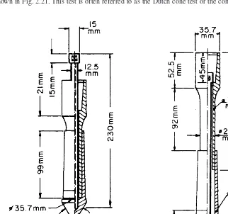
SUBSURFACE EXPLORATION 2.21
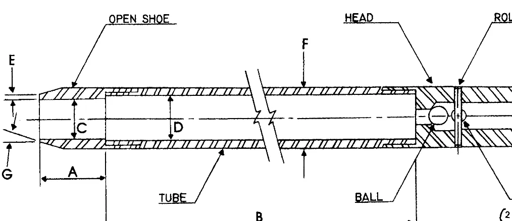
Drill rod
Ball check valve Vents
Sampler head Set screws
Casing
Sampling tube
Sample
Cutting edge with inside clearance
Thin-wall open drive sampler Thick-wall open drive sampler
Shoe with inside clearance Sample Casing Barrel-solid or split wall Outside vents Check valve Sampler head Rod coupling Drill rod