Technique of Standing Up From Prone Position of a Soccer
Robot
Nur Khamdi1, Mochamad Susantok2, Antony Darmawan3
1Mechatronics Department at Polytechnic of Caltex, Indonesia
2Telecommunication Department at Polytechnic of Caltex, Indonesia
3Student of Mechatronics Department at Polytechnic of Caltex, Indonesia Email : 1[email protected], 2[email protected],
Abstract
One of the humanoid robots being developed in the field of sports is a soccer robot. A soccer robot is a humanoid robot that can perform activities such as playing football. And a variety method fall down of robot soccer such: falling down toward the front direction, side direction, and rear direction. This paper describes the most stands up methods of a soccer robot from its prone position. The proposed method requires only limited movement with degrees of freedom. The movement standing-up of soccer robot has been implemented on the real robot. Tests we performed showed that reliable standing-up from prone position is possible after a fall and such recovery procedures greatly improve the overall robustness of a Soccer Robot.
Keywords: prone position; standing up; soccer robot
1. INTRODUCTION
In general, the movements of humans are very dynamic and skilled, the movements such as of walking, running, jumping, and dancing that have a high body balance point. All these movements have attachments between the body’s balance points with the body’s control system that control the human body. In the movement of walking or running imbalances occur that can lead to falling while walking or running. There are various conditions of falling down, such as the prone and supine posture positions. When in a state of falling, the system control will work to instruct members of the body to stand up.
developed in the field of sports is a soccer robot. A soccer soccer is a humanoid robot that can perform activities such as playing football.
Falling down in the game of football is a matter of course. During a football match, a player can fall down which is caused by various reasons, suchas clashing between players, tripping on the ground due to uneven field conditions and an imbalance in the body while running. These certainly happen in a soccer playing playing robot too. And a variety of methods of falling down by a soccer robot are such as falling down toward the front direction, the side direction and the rear direction. To solve these problems, the scientists must design a robot that can do things after falling; that it can stand up on its own without any help. This design includes mechanical and control system of a robot for all conditions and movements. This results in whole-body motions with sequences of support points. The many degrees of freedom of humanoid robots and the changing contact points make it difficult to apply the conventional motion-planning techniques. On the other hand, humans devise a variety of strategies to get up from the ground after falling [1][2]. The research will be focused on the movements of the soccer robot systems when standing up from the prone position.
2. RELATED WORKS
A standing-up routine is triggered when the robot has fallen over with high certainty. To determine this state, the attitude sensors are interpreted. If the robot is tilted more than 45◦ for more than one second, we assume that the robot has fallen. As our robots cannot lie other than facing upwards or downwards on a flat surface, we only have to inspect the sign of the sagittal tilt in order to recognize its posture.[2] The main problem of standing up from the prone posture is that the knees of a humanoid robot cannot be bent in positive direction. If it was possible, standing up from the prone posture would be similar to standing up from the supine posture.
In order to estimate the robot’s center-of-mass position accurately, we additionally used an inertial parameter identification technique that fit mass and center-of-mass link parameters from measured force data. We employed a physics-based robot simulation to analyze the kinematics and dynamics of getting up. The standing-up routines have been implemented on the real robot as well and that reliable standing-up is possible after a fall and that such recovery procedures greatly improve the overall robustness of bipedal locomotion.[2]
To obtain as accurate an estimate as possible, we used an inertial parameter estimation technique to identify the mass and center of mass parameters of a 5 link planar robot model. We then used this model to estimate the robot’s COM position during the motion.[11]
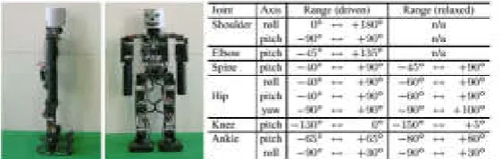
Figure 1. Sagittal and lateral view of our robot Jupp and the range of motion for its joints at the table. [1]
3. ORIGINALITY
Since in soccer games physical contact between the robots is unavoidable, the walking patterns are disturbed and the robots might fall. Using their attitude sensors, the robots detect a fall, relax their joints before impact, classify the prone or supine posture, and trigger the corresponding getting-up sequence. We designed the getting-up sequences in a physics-based simulator using sinusoidal trajectories. [1]
A standing-up routine is triggered when the robot has fallen over with high certainty. To determine this state, the attitude sensors are interpreted. If the robot is tilted more than 45◦ for more than one second, we assume that the robot has fallen. As our robots cannot lie other than facing upwards or downwards on a flat surface, we only have to inspect the sign of the sagittal tilt in order to recognize its posture.
We developed standing-up routines for the Robot Soccer domain from the prone position under the following assumptions:
• The surface is flat carpet (soft, moderate friction).
• No obstacles conflict with the robot’s motion during the standing-up routine.
• The robot is lying straight on the surface with all joints moved to zero positions.
Motion Generation: The standing-up motions are generated by setting target positions for individual joints. We use sinusoidal trajectories, which are smooth and natural for static movements, whereas for dynamic motions the distinctive points of target velocity and acceleration being zero or maximal are obtained easily from the waveform itself.
4. SYSTEM DESIGN
Using kinematic of 3 methods for the movement of stand up from prone position. And each method is divided into 4 phase proceses of movement of prone to stand up position, difference of phase of this movement which in analysis.
4.1 First Method Prone Fall
Phase I. Move the upper body into a sit-up posture and move the arms into a supporting position behind the back.
Phase II. Move into a bridge-like position using the arms as support. Phase III. Move the COM over the feet by swinging the upper body to the
front.
Phase IV. Move the body into an upright posture.
the surface, while the hip and the spine pitch joints are bent in. Meanwhile, the elbow has to be rotated further to prevent the forearms from touching the ground. As soon as possible, the elbows start moving back to straighten the arms, while the shoulder pitch joints are rotated further into negative direction. The shoulder roll joints are moved back to zero. This brings the arms into a backward position, which will support the later bridge-like position. During the alignment of the arms, when the hip pitch joints and the spine have reached their target positions, the legs are bent in by folding the knees to their negative limit. The twist of the hip is compensated by rotating the spine further, such that the robot remains sit-up. In Phase II, the arms are straightened in the elbows, and the hip pitch and spine joints are moved to zero, such that the hip is lifted. The ankle pitch joints rotate positively to let the hip and the knees shift forward.
4.2 Second Method Prone Fall
When the robot falls, the leg automatically split by expanding left leg to the side, ready for Phase II. In Phase II, the hand is pushing the ground then pushes the body, making it possible for foot to touch the ground fully. In this Phase the robot is in squat position. Then in Phase III the hips moves the body perpendicular from the ground. Then in Phase IV the arm stays freely by sides and the knees extended, making the body elevated
In Phase I, the hips bring the foot closer to the body. In Phase II the arm push the ground together with the hips bringing the robot up making it to the Phase III to the squatting position. Then last Phase the hips elevated and rise the body up.
5. EXPERIMENT AND ANALYSIS
success rates of 100 percent. In order to find the most usefull methode, we conduct a test to all the methods found (3 methods was used in this project).
5.1 First Method Prone Position
When the robot falls to the front, the limit switch is activated. By activating limit switch, the program to standing up from the prone falls is activated. This program makes both arm pinched between the armpits. Then rotate the arm so the lower arm faced the ground directly. Next the lower arm is extended, and the feet is facing the ground directly, making it possible for the robot to stand on its knees. Then left arm is extended to the back, as precaution from falling to the front again by the unstable load. Next, the left foot is extended to the left side, and the right foot is elevated in the same time. Next the left arm swings to the front sides, making it has enough of momentum to be in squatting position. And then both arm stays freely by the sides, on standby position. Then the left hand swings a little bit to the front while the right leg arise , continued by left leg. And last, both legs slowly rising until estimated position then begin walking.
(a) I (b) II
II (c) III (d) IV
IV (e)
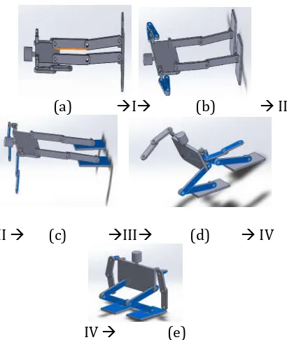
Figure 2. (a) – (e) starting and end position of phases I – IV when standing up from prone position of first method
(a) Phase I movement
(b) Phase II movement
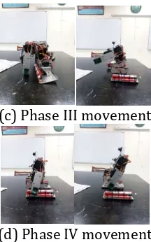
(c) Phase III movement
(d) Phase IV movement
Figure 3. Image sequence showing dynamic standing up from prone position of first method
Figure 4. Analysis torque at first method with solid works software
With using motion analysis in solid works application, first method for prone position motion get result for robot’s knee motor torque as shown in the figure 4. For five seconds working time, shown that the highest torque needed for the robot knee is 1000Nmm. If the value convert to KgCm as the national standard of motor servo torque.
T = , ∗
T = 10,19 KgCm
doesn’t break the motor servo’s torque limit as shown in the first method motion analysis
5.2 Second Method Prone Position
(a) I (b) II
II (c) III (d) IV
IV (e)
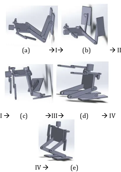
Figure 5. (a) – (e) starting and end position of phases I – IV when standing up from prone position of second method
(a) Phase I movement
(c) Phase III movement
(d) Phase IV movement
Figure 6. Image sequence showing dynamic standing up from prone position of second method
In this method, when the robot falls, the leg automatically split. And in that position the hand is pushing the ground, making it possible for foot to touch the ground fully. Next the hip moves the body to be perpendicular by the ground. Then the arm stays freely by sides and the knees extended, making the body elevated and stands firmly. This method is not fully recommended, because when the arm pushing the ground, the robot is still unstable due to the splitting leg.
Figure 7. Analysis torque at second method with solid works software
With using motion analysis in solid works application, second method for prone position motion get result for robot’s knee motor torque as shown in the figure 8. For seven seconds working time, shown that the highest torque needed for the robot knee is 1100 Nmm. If the value convert to KgCm as the national standard of motor servo torque.
T = , ∗ T = 11,21 KgCm
5.3 Third Method Prone Position
When the body falls to the front, the hand is brought to the sides, when the feet facing the ground. Then the hands set position to push the ground, bringing the body up. Then the knees bend a little, making the body a little more stable. A next knee is bended, making it in squatting position. And last the hips raising the body. This method is not fully recommended, because the way the hips bended, the head is at risk of being crooked, and in the worst possibility, snapped.
(a) I (b) II
II (c) III (d) IV
IV (e)
Figure 8. (a) – (e) starting and end position of phases I – IV when standing up from prone position of third method
(a) Phase I movement
(c) Phase III movement
(d) Phase IV movement
Figure 9. Image sequence showing dynamic standing up from prone position of third method
Figure 10. Analysis torque at second method with solid works software
With using motion analysis in solid works application, third method for prone position motion get result for robot’s knee motor torque as shown in the fig 10. For seven seconds working time, shown that the highest torque needed for the robot knee is 1160 Nmm. If the value convert to KgCm as the national standard of motor servo torque.
T = , ∗ T = 11,82 KgCm
6 Prone Position Method Analyst
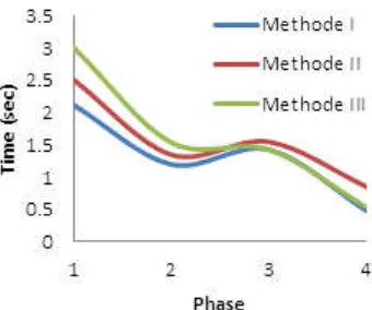
Figure 11. timing respond of phase for I – III methods
Fig 11 show timing response of highest in phase I, this is due to torque movement of motors in phase 1 largest. And timing response of lowest in phase IV, when in position phase IV motor movement to move the body of the humanoid robot does not require a large torque so that the timing response is fast. Overall movement of the motor in each phase of the three methods, timing response of fastest on method I for standing up from prone position in method I.
The main problem of standing up from the prone position is that the knees of a humanoid robot cannot be bent in the forward direction due to movement limitation of motor. If it was expected, standing up from the prone position would be similar with supine position. From the three methods in this paper, makes both arm pinched between the armpits. Then rotate the arm so the lower arm faced the ground directly. Next the lower arm is extended, and the feet is facing the ground directly, making it possible for the robot to stand on its knees. Then left arm is extended to the back, as precaution from falling to the front again by the unstable load. Next, the left foot is extended to the left side, and the right foot is elevated in the same time. Next the left arm swings to the front sides, making it has enough of momentum to be in squatting position. And then both arm stays freely by the sides, on standby position. Then the left hand swings a little bit to the front while the right leg arise , continued by left leg. And last, both legs slowly rising until estimated position then begin walking.
6. CONCLUSION
1 Move the upper body into a sit-up posture and move the arms into a supporting position behind the back.
2 Move into a bridge-like position using the arms as support.
3 The motor servo that used for the robot’s knee has the highest torque 13Kgmm.
4 Move the COM over the feet by swinging the upper body to the front. 5 Move the body into an upright posture.
Acknowledgements
This research was supported/partially supported by kemenristekdikti of Indonesian with applied technology research programs. We thank our colleagues from Caltex of Riau Polytechnics who provided insight and expertise that greatly assisted the research, although they may not agree with all of the interpretations/conclusions of this paper.
We thank mechatronics team of PCR for assistance with particular technique and methodology.
REFERENCES
[1]Jörg Stückler, Johannes Schwenk, and Sven Behnke, “Getting Back on two feet: Reliable standing up Routines for Humanoid Robot”, University of Freiburg, Computer Science Institute Georges-Koehler-Allee 52, 79110 Freiburg, Germany.
[2]A. van Sant. Rising from a supine position to erect stance. Physical Therapy, 68:185-192, 1988.
[3]Herman Bruyninckx, “Robot Kinematics and Dynamics”, Katholieke Universiteit Leuven Department of Mechanical Engineering Leuven, Belgium.
[4]K. Terada, Y. Ohmura, and Y. Kuniyoshi. Analysis and Control of Whole Body Dynamic Humanoid Motion - Towards Experiments on a Roll-and-Rise Motion. Proc. of the IEEE/RSJ Int. Conf. on Intelligent Robots and Systems, 2003.
[5]M. Hirose, Y. Haikawa, T. Takenaka, and K. Hirai. Development of Humanoid Robot ASIMO. Int. Conf. on Intelligent Robots and Systems, Workshop 2, 2001.
[6]F. Kanehiro et al., The First Humanoid Robot that has the Same Size as a Human and that can Lie down and Get up, Proc. of the 2003 IEEE Int. Conf. on Robotics & Automation, Taipei, Taiwan, 2003.
[7]M. Vukobratovic, A. Frank, and D. Juricic. On the Stability of Biped Locomotion. IEEE Transactions on Biomedical Engineering 17(1), S. 25-36, 1970.