Tracking and Formation Control of Leader-Follower
Cooperative Mobile Robots Based on Trilateration Data
Endah Suryawati Ningrum, Rizky Yuniar Hakkun, Ali Husein Alasiry
Politeknik Elektronika Negeri Surabaya (PENS)
Raya ITS Sukolilo Surabaya, telp. +62-(031)5947280/fax. +62-(031)5946114 E-mail: [email protected]
Abstract
This research deals with formation control of swarm robot based on changing of robot’s relative positional data. A follow the leader movement with simple triangle formation case is applied with three robots; a leader with two followers. Trilateration method is used as a method of determining the position of the leader robot from the follower robots using the distance to the reference point (local positioning). Follower robots are designed to follow every movement of the leader on a formation position. The controller is designed to maintain the formation position of the follower robots relatively to the leader. As a uniqueness, a relative positional control method by using bearing angle and distance error is proposed instead of the common Cartesian positional error control. From the experiment which conducted in maximum distance between the robots,it was obtained a maximum error approximately 56%. The follower robots are able to follow any changes in motion of the robot leader with average distance error of 36%.
Keywords: Cooperative mobile robot, formation control, trilateration, follow the leader
1. INTRODUCTION
The study of multiple-robot systems naturally extends research on single-robot systems, but is also a discipline unto itself: multiple-robot systems can accomplish tasks that no single robot can accomplish, since ultimately a single robot, no matter how capable, is spatially limited. The term collective behavior generically denotes any behavior of agents in a system having more than one agent. [1]
limited. Formations allow individual team members to concentrate their sensors across a portion of the environment, while other members cover the rest. Air Force fighter pilots for instance, direct their visual and radar search responsibilities depending on their position in a formation. The approach is potentially applicable in many other domains such as search and rescue, agricultural coverage tasks and security patrols [7].
To achieve a formation, positional data of each robot in the team should be known. In known cases, absolute or relative Cartesian positional data, i.e. X and Y of a leader or a follower robot, are always used as lone primary data to the formation control algorithm. A predefined position is given as target, then a threshold value applied to the position error.
This research builts three robots, one robot leader and two follower robots with an emphasis on ability to establish autonomous coordination between robots in follow the leader formation. Follower robot can find position relative to the leader robot using trilateration method by ultrasonic signals to determine their relative positions. As uniqueness, angular position derived from relative position of each follower, we called “bearing angle” is also used as additional information instead of the “bearing distance”.
2. RELATED WORKS
The idea of making robots with a specific function and capable of inter-robot collaboration (cooperative mobile inter-robots) will be more efficient both in cost and time [2]. Maxellbot is a swarm robot made at the University of Wyoming, USA. The robots are equipped with a localization system using ultrasonic transducer to determine the relative position of the robot around it [3].
A formation can be achieved by maintaining the follower robot relative position to other followers or the leader. According to [7], at least three techniques for formation position determination are identified: (1) Unit-center-referenced: a unit-center is computed independently by each robot by averaging the x and y positions of all the robots involved in the formation. Each robot determines its own formation position relative to that center.(2) Leader-referenced: each robot determines its formation position in relation to the leader robot. The leader does not attempt to maintain formation; the other robots are responsible for formation maintenance. (3) Neighbor-referenced: each robot maintains a position relative to one other predetermined robot.
3. ORIGINALITY
parameters should be derived, conventional method has more computational error.
In this paper, we proposed a new method of positional control by using bearing distance error and bearing angle error. This method utilizing directly measured inter-robot distance as the primary control parameter. The second control parameter is bearing angle that is deriver from the positional data.
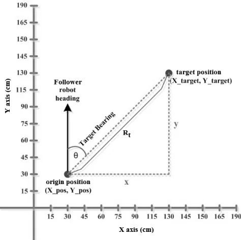
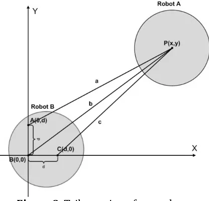
The principle is the leader robot is assumed as a point from which to search position. Leader robot would send a beacon to be received by the three sensors on each follower robot. Differences in time receive among the three sensors is used as a comparison to be concluded where the robot is located with respect to the origin B(0,0). Figure 1 show an example of the proposed position control method.
Figure 1. Movement control illustration.
= _ − _ (1)
= _ − _ (2)
In Figure 1, origin position (X_pos, Y_pos) and the target position (X_target, Y_target) is inputted to the leader robot. Once known coordinates of the origin and target coordinates, x and y coordinates of the start of the target
From equations (1) and (2) distance can be known x and y coordinates of the initial distance to the destination coordinates. Once thetarget x and y position is known, the distance from the initial position to the target can be determined using the following equation (3).
Once the distance goal coordinates are known, then the angle of the target (θ), or called target bearing angle can be determined using equation (4).
= 2 (4)
Target bearing is used to control the movement of the robot, in the above example obtained by the target bearing by 45º so that the robot should move to the right, after the robot moves the robot will calculate the above parameters and the robot will move straight if the target bearing is 0°.
4. SYSTEM DESIGN 4.1 Mechanical design
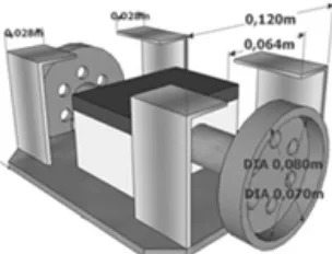
There are two kinds of robot in the follow the leader scheme; the leader robot and the follower robot. We use similar differential drive (DD) mechanism as shown in figure 2, for both robot types.
Figure 2. Differential drive mechanic of the robot
4.2 Electrical circuit design
Figure 3. Diagram of a leader robot
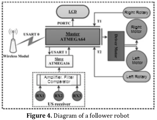
Figure 4 shows diagram block of the follower robot. In general the follower has the same components as a leader with exception on the US transmitter unit which is replaced with three US receivers that work simultaneously to collect leader’s US beacon in three fixed points of trilateration. Amplifier, filter, comparator unit will separate the outputs from RX1, RX2 and RX3 and generate three different pulses according to US beacon arrival time.
Figure 4. Diagram of a follower robot
4.3 Omnidirectional US sensor design
Figure 5. Omnidirectional ultrasonic sensor design
In follow the leader scheme, the leader robot will send a US beacon together with synchronization time broadcast packet through the RF module. The RF receivers in all followers will receive the synchronization packet and start to count the US time of flight (ToF). Following, all the US receivers will receive the US beacon in different time according to their ranges from the leader’s US transmitter.
Figure 6. Photo of the leader robot (left) and a follower robot
4.3. Leader-follower distance measurement
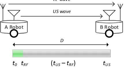
To measure distance between the leader and a follower robot, we use principle of distance measurement between two point using differential speed of ultrasonic and electromagnetic, i.e. light, described in [6]. We use radio frequency (RF) that has similar properties to replace light. Ultrasonic (US) wave has properties that are much similar to sound. Propagation velocity of ultrasonic wave (cUS) and velocity of RF (cRF) are differs
considerably.
A Robot B Robot
RF wave
US wave
(tUS – tRF)
tR F
t0 tUS
D
Figure 3 illustrate the distance measurements between two robots. A robot send a RF and US waves at once to B robot. RF wave which is come first, trigger B robot to start the count the arrival time of US wave. Considering propagation velocity of these two media, if ultrasonic wave and RF dispatched simultaneously at time t0 [sec] from the RF transmitters to
observation point (receivers) that separated in a distance of D [m]. Since it is
considered that cRF>>cUS then D becomes:
Trilateration is a method to determine the intersection of three areas of known surface circle center and radius. In network theory this method is often used to calculate the position of the nodes when the nodes with known distances flare points as shown in figure 1.
Figure 8. Trilateration of two robots
In our previous research [5], as in Figure 8, the trilateration is applying into two robots, a leader with a follower.We can describe the position of the leader (robot A) as origin frame to the follower (robot B), with three points A(0,d) , B(0,0) and C(d,0) are the three known points inside the follower body. By substitute all known parameters with the four known parameters named a, b, c and d,the final equations are:
4.5 Follow the leader movement control algorithm
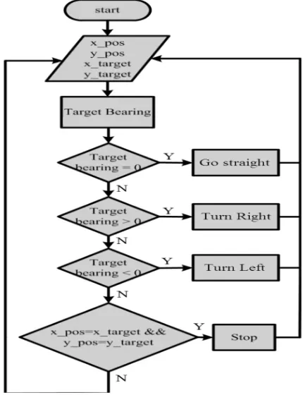
Figure 9 shows the flow diagram of a follower robot movement control algorithm. From the initial position, a relative position of leader start (x_pos, y_pos) and target (x_target, y_target) are inputted, then the follower can determine the target bearing and decide the action to whether go straight, turn left or turn right, and finally stops when the target position is achieved.
Figure 9. Follower robot algorithm in following its leader
5. EXPERIMENT AND ANALYSIS
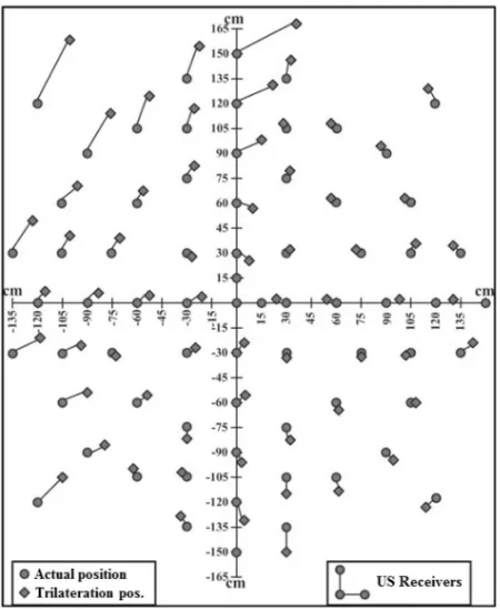
5.1 Trilateration positional experiment
Figure 10. Trilateration test result example of a follower robot
5.2 Follow the Leaderexperiment
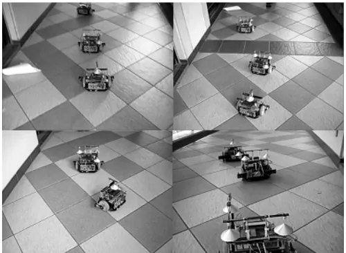
The next experiment is the follow the leader test. The purpose is to observe the ability of the robot to maintain a simple in line formation: leader—follower 1—follower 2, while leader robot moves, follower should be able to follow it in certain distance. Figure 11 left photo shows the formation with initial distance between robots set to 30 cm, while the right photo shows the formation when the distance is set to 50 cm.
Figure 11. Follow the leader test photo for initial distance between robots 30 cm (left) and 50 cm (right)
the robot to move around corridor of a building. Follower robots can follow the leader constantly; however, follower 2 robot some time lost its direction due to imperfect construction of its US cone. Overall result of trilateration error during in line follow the leader for two followers, the average location error is around 24% to 48% respectively.
Figure 12. Follow the leader running test around corridor of a building
6. CONCLUSION
Some conclusions can be drawn from this research:
• Reading of the position of the robot by robot leader follower with trilateration method, the robot is able to determine the position of follower robot leader with a maximum distance of 150 cm and a maximum error of 56% in quadrant 2. Whereas in quadrant 1 coordinate readings have a maximum of 36%.
• While following the leader, follower robot is able to follow any motion changes, except when both follower in line in parallel with target bearing around 90º. Average distance error is 24% for the follower robot 1 and 48% for the follower robot 2.
REFERENCES
[1] Sergio Monteiro, and Estela Bicho, Robot Formations Robots Allocation and Leader-Follower Pair, Proceeding-IEEE International Conference on Robotics and Automation,ICRA 2008.
[2] P.M. Maxim, S. Hettiarachchi, W.M. Spears, Trilateration Localization For Multi-Robot Teams, University Of Wyoming, Laramie, Wyoming G2070, USA
[4] N. Bredeche, Y. Chevaleyre, The Robot Swarm Re-localization Problem, 5th IEEE International Conference on Robotics and Biomimetics (ROBTO), 2008.
[5] E.S.Ningrum, A.Setiawan, A.H. Alasiry, “Prototype of Cooperative Mobile Robots With Trilateration Localization Method”, 1st IFSA International Conference, Surabaya, 2011
[6] S. Ohyama, A.H.Alasiry., J. Takayama, A. Kobayashi, Determining 2D positions of sensor network nodes for temperature distribution measurement, Sensors and Actuators A Physical, 135(1):203-208, 2007 [7] T. Balch, R.C. Arkin, Behaviour Based Formation Control for