04/04/2009 1
PENGANTAR
Motor Induksi
Oleh
Mesin Listrik
Transformator
Mesin Arus Bolak-balik
Mesin Arus Searah
04/04/2009 3
Mesin Arus Bolak-balik
Mesin Sinkron Motor Sinkron Generator Sinkron Mesin Asinkron Motor Asinkron Generator Asinkron
Jumlah fasa
Mesin tiga fasa
Motor Induksi
Motor kondensor sinkron Generator Sinkron
Mesin satu fasa
Motor Split-phase Motor Capasitor Motor Shaded-pole Motor Universal
04/04/2009 5
Mesin Listrik yang lain
Mesin DC Motor DC Penguat terpisah Penguat sendiri • Serie • Shunt
• Compound (long, short, differentiative, commulative)
Generator DC
Spesial Motor
Stepper motor
Linier stepper motor
Jenis Konstruksi Rotor dan
Kutub
Jenis Rotor Sangkar
(squerell-cage rotor)
Jenis Rotor Lilit ( wound rotor)
04/04/2009 7
Keuntungan Motor AC
Konstruksi kuat
Effisiensi tinggi
Biaya pemeliharaan murah
Starting mudah
Effisiensi tinggi pada
Kerugian Motor AC
Kontrol Putaran Susah
Torsi start kecil
Putaran akan turun bila
04/04/2009 9
Konstruksi Mesin AC
Bagian Stator : Inti dan Lilitan stator
Bagian Rotor : Inti dan Lilitan rotor
Rotor sangkar (sqeurell-cage rotor) Rotor Lilit (wound rotor)
Konstruksi MI
Some motor frames are sized so that just the surface area is suitable
Some motor frames are sized so
Some motor frames are sized so
that just the surface area is suitable
that just the surface area is suitable
Blowers may be added to motors to allow operation at low speed including “0” RPM with 100% Torque continuous
Blowers may be added to
Blowers may be added to
motors to allow operation at
motors to allow operation at
low speed including
low speed including ““00”” RPM RPM with 100% Torque continuous
04/04/2009 11
Types of AC Motors
Definite purpose “laminated frame” designs provide higher power
densities & improved torque to inertia performance.
Definite purpose
Definite purpose ““laminated framelaminated frame”” designs provide higher power
designs provide higher power
densities & improved torque to
densities & improved torque to
inertia performance.
inertia performance.
T-Frame Construction Motors allow commonality in footprint & shaft height.
T
T--Frame Construction Motors allow Frame Construction Motors allow commonality in footprint & shaft
commonality in footprint & shaft
height.
height.
Match Motor type to meet your needs!
Bagian motor Induksi
Motor Frame
Motor Frame
Assembly
Assembly
Rotor & Shaft
Rotor & Shaft
Stator Winding
Stator Winding
Assembly
04/04/2009 13
Persamaan yang digunakan
Hukum Ampere Hukum Farady Hukum Kirchoff∫
H.dl
=
∑
NI
dt
Nd φ
e
=
∑
I
= 0
∑
IZ
=V
04/04/2009 15
Medan Putar
Medan putar terjadi pada sumber tiga fasa yang diberikan
Prinsip Kerja motor induksi
3fasa
Kumparan stator diberi tegangan 3 fasa akan
timbul medan putar dengan kecepatan :
Ns = 120f / p
Medan putar akan memotong konduktor pada
rotor, sehingga akan menimbulkan tegangan induksi pada lilitan rotor sebesar
04/04/2009 19
Karena lilitan rotor merupakan lilitan yang tertutup, maka akan
ada arus yang mengalir pada rotor
Adanya arus dalam medan magnet, akan timbul gaya F pada
rotor
Gaya dikalikan dengan jari-jari koduktor rotor akan
menghasilkan kopel (torsi)
Jika torsi yang dihasilkan lebih besar dibandingkan dengan
torsi beban, maka rotor akan berputar sesuai dengan arah medan putar
Agar tagangan E2s tetap ada, maka diperlukan perbedaan
Perbedaan antara ns dengan nr dinyatakan dengan persamaan slip (s)
• S = {(ns – nr)/ns} 100%
Kemungkinan
s = 0 Kondisi motor diam
( ) ( ) ( ) ( )2 2 2 2 2 2 2 2 2 2 2 SX R SE X R E I s s + = + = ( ) ( )2 2 2 2 2 2 / S X R E I + = Atau
04/04/2009 23 ⎟ ⎠ ⎞ ⎜ ⎝ ⎛ − + = S S R R S R2 / 2 2 1 Karena Maka ⎟ ⎠ ⎞ ⎜ ⎝ ⎛ − S S R2 1
s I 0 I I1 1 R X1 s I m I 1 R s I 1 X
04/04/2009 25 V1 R’2 X’2 ⎟ ⎠ ⎞ ⎜ ⎝ ⎛ − S S R'2 1 R1 X1 m JX s I IR m I > > v
2 2 2 2 2 2 1 2 ) ( ) / ( ' X a S R a E I + = 2 2 2 2 2 2 2 2 ) ( ) / ( / cos X a S R a S R a impedansi tahanan + = = ϕ ϕ ω ω 3 E1I '2 cos P T = = ( )
(
)
(
)
2 2 2 2 2 2 2 2 2 2 1 3 X a S R a R Sa V T + = ω04/04/2009 27
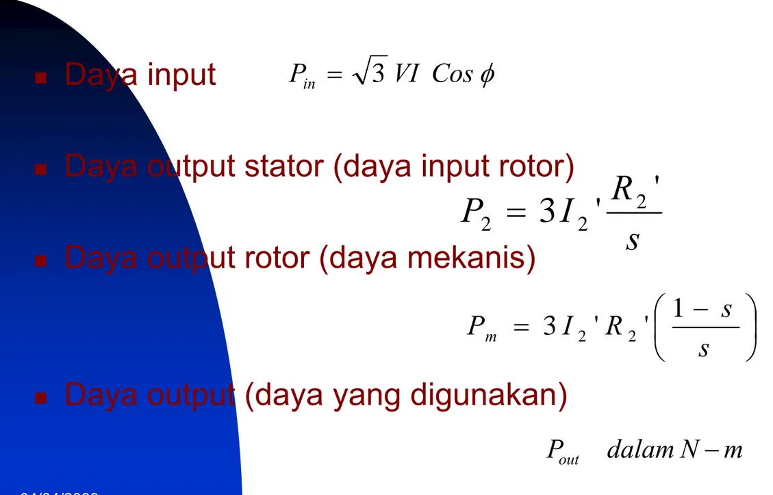
Diagram daya
Daya input
Daya output stator (daya input rotor)
Daya output rotor (daya mekanis)
Daya output (daya yang digunakan)
φ Cos VI Pin = 3
s
R
I
P
2=
3
2'
2'
⎟ ⎠ ⎞ ⎜ ⎝ ⎛ − = s s R I Pm 3 2 ' 2 ' 1 m N dalam Pout −04/04/2009 29
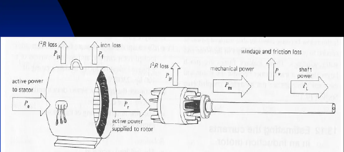
Input power Psup
Stator Copper loss 3 Ista2 Rsta
Rotor Copper loss 3 Irot2 Rrot Stator Iron loss
3 Vsta2 / R c Ventilation and friction losses Output power Pout Air gap powerPag Developed power Pdv = 3 Irot2 Rrot (1-s)/s Air gap
04/04/2009 31
Karakteristik Torsi-Slip
Gambar 4 2 2 2 2 2 2 2'
'
'
3
X
s
R
sR
V
T
+
=
ω
04/04/2009 33
Starting Torque
Pull-up Torque
Break down Torque
Pengaturan Putaran Motor
Induksi
Tegangan Input Frekuensi input Tahanan Rotor Jumlah kutub04/04/2009 39
METODA STARTING
Pada rotor belit :
digunakan tahanan mula yang besarnya dipilih sedemikian sehingga torsi start = torsimax. Setelah motor berputar, dalam keadaan nominal rotor dihubung singkat.
Pada rotor sangkar :
a. Untuk daya kecil dapat distart langsung b. Start dengan auto trafo
Machine design Speed sensorless Machine Theory Non-linear control Real-time control DSP application Utility interface Renewable energy
04/04/2009 41
04/04/2009 43
Klasifikasi Motor Induksi
berdasar temperatur
Motor Induksi Klas A ()
Motor Induksi Klas B (80oC) Motor Induksi Klas C ()
Motor Induksi Klas D ()
Motor Induksi Klas E (40oC) Motor Induksi Klas F (75o C)
Berdasar operasi
Drip-proof motor
Splash-proof motor
Totally enclose. Non-ventilated
Totally enclose, fan-cooled motor
Name plate motor
Jenis Motor dan jumlah fasa Tegangan nominal Arus nominal Frekuensi kerja Power factor Jenis isolasi Temperatur operasi
04/04/2009 49
Pengaman Motor Induksi
Thermal Overload
Over current/ over load
Under/over voltage Under frequency Pole slip Out of excitation Over flux Negative sequence De-rating Factor Earth Foult
Pemilihan dan Penggunaan
Motor Induksi
Standar dan klasifikasi motor
Klasifikasi pendinginan
Drip-proof, splash-proof, totally enclose, totally
enclose fan-cooled, Explosion-proof,
Klasifikasi sesuai dengan sifat listrik dan mekanis ;
Standart, Torsi start tinggi, slip tinggi.
Ukuran motor dalam HP
Pemilihan putaran, pengereman,
04/04/2009 51
INTRODUCTION TO ELECTRIC DRIVES - MODULE 1
Torque and speed profile
10 25 45 60 t (ms)
speed (rad/s)
100
The system is described by: Te – Tload = J(dω/dt) + Bω
J = 0.01 kg-m2, B = 0.01 Nm/rads-1 and Tload = 5 Nm.
What is the torque profile (torque needed to be produced) ? Speed profile
INTRODUCTION TO ELECTRIC DRIVES - MODULE 1
Torque and speed profile
10 25 45 60 t (ms) speed (rad/s) 100 0 < t <10 ms Te = 0.01(0) + 0.01(0) + 5 Nm = 5 Nm 10ms < t <25 ms Te = 0.01(100/0.015) +0.01(-66.67 + 6666.67t) + 5 = (71 + 66.67t) Nm 25ms < t< 45ms Te = 0.01(0) + 0.01(100) + 5 = 6 Nm l e B T dt d J T = ω + ω +
04/04/2009 53
INTRODUCTION TO ELECTRIC DRIVES - MODULE 1
Torque and speed profile
10 25 45 60 speed (rad/s) 100 10 25 45 60 Torque (Nm) 72.67 71.67 -60.67 -61.67 56 t (ms) t (ms) Speed profile torque profile
INTRODUCTION TO ELECTRIC DRIVES - MODULE 1
Torque and speed profile
10 25 45 60 Torque (Nm) 70 -65 6 t (ms)
For the same system and with the motor torque profile given above, what would be the speed profile?
J = 0.001 kg-m2, B = 0.1 Nm/rads-1 and Tload= 5 Nm.
Electric Drives 55
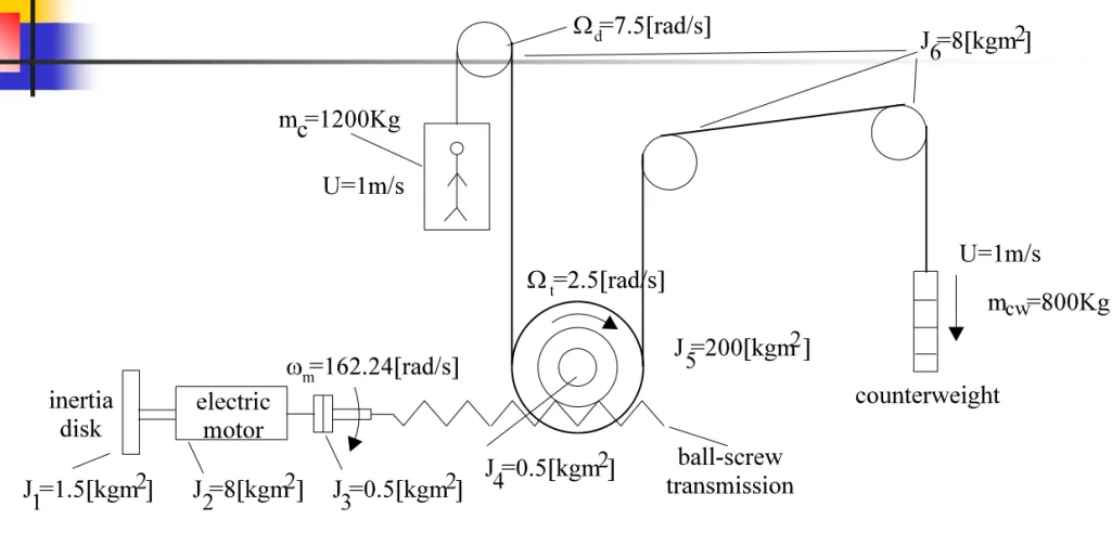
Example 1.3. gear - box drive torque / time curve
Let us consider an electric drive for an elevator with the data shown in figure 1.11.
Figure 1.11. Elevator electric drive with multiple mechanical transmissions and counterweight