See discussions, stats, and author profiles for this publication at: https://www.researchgate.net/publication/233906658
Gyrocompasses–their condition and direction
of development
Book · January 2008
DOI: 10.13140/2.1.3597.4081
CITATIONS
0
READS
54
1 author:
Andrzej Felski
Polish Naval Academy
81PUBLICATIONS 124CITATIONS
SEE PROFILE
International Journal on Marine Navigation
and Safety of Sea Transportation
Volume 2 Number 1 March 2008
Gyrocompasses – Their Condition and
Direction of Development
A. Felski
Polish Naval Academy, Gdynia, Poland
ABSTRACT: Gyroscopic compass, the main source of information about the heading on modern ship, is celebrating its centenary. In fact, nowadays it is commonly used on the ships in the form invented by Herman Anschutz before the Second Word War. However in the last decade we observe stormy evolution of completely different installations, which may substitute the well known gyro. Different kinds of devices, which could be used for heading determination, will be shortly presented and classified. Author’s thesis is that the new solutions are better than the old ones, nevertheless at the moment they are not in use only because of the mariners’ conservatism.
1 THE QUESTION OF TERMINOLOGY
The present year may be funded as centenary of creating of the gyrocompass, as in 1907 Anschutz received the first patent for apparatus capable to supersede magnetic one. Meantime a lot of producers occurred as well as many diversified structures of gyrocompasses raised so in author’s opinion it is excellent time to summarize and set in order the knowledge in this topic.
The discussion should start on sense of the name “gyroscope” as it has influence on the apprehension what is the gyrocompass. The term “gyroscope” originates with Foucault, who demonstrated that Earth rotates in experimental way. He made it in 1852 in Paris, using a spinning disc. Foucault’s demonstration was based on the fact that the rotation axis of the disc must remain fixed in inertial space in the absence of applied torques. If so, the direction of the disc’s axis with respect to the Earth changes, as the Earth rotates underneath it. This is the essence of the name “gyroscope” which occurs by joining of two Greek words “gyros” and “skopos”. The first one means “rotation” and second one - “to view”. So according to Foucault gyroscope means some
devices to prove Earth rotation, with similarity to microscope – devices for observing microscopic objects or telescope – devices for observing distant objects. This fact is very important from my point of view, as in common opinion gyroscope is a swirling body of wheel shape which keeps the constant direction in the space. So according to this opinion the gyrocompass is a device constructed on gyroscope.
The proper interpretation is that gyrocompass is the device which is capable to show the direction of the Earth axis by measuring the Earth rotation by means of the mechanical gyroscopes (in the old manner) or by any other devices capable to measure the rate of turn.
fixed direction and the gimbal angles provide readout of the total angular displacement of this direction from body-fixed axis directions. Such devices are now classified as directional gyroscopes in opposition to rate turn gyroscopes. This second type of gyroscopes, sometimes called as one-degree-of freedom (also SDF – single degree one-degree-of freedom), has been invented around 1950. A rate gyroscope provides a signal proportional to rate of angular velocity of the carrier. The heart of this type of device is a wheel running at high speed too, but attached to the instrument case by torsion bar. Carrier’s rotation enforces the main axis of the instrument in changing its direction in the inertial space by some angle. And this angle provides the information about the carrier’s rotation, which could be measured, usually by some electromagnetic instruments. Flexibility of the torsion bar enforces the spinning wheel go back to previous position, after the carrier stops its turning. Instead of torsion bars sometimes electric pick-off assemblies are applied.
Then, in the sixties of the XX century Dynamically Tuned Gyro (DTG) was designed. Firstly, this kind of gyro was invented around 1920 by Kearfott, but for 40 years it was inadequate for the market. DTG is a kind of gyroscope that uses a spinning fly wheel on a specific, flexures universal joint. Normally that wheel is very unstable, but the flexure spring stiffness affects on dynamic inertia of the wheel, so at particular speed these two interactions cancel themselves. The resulting sensor is very stable in inertial space, extremely small and relatively cheap.
Then, development of the laser technology influenced on the method of angular velocity measurement methods. So in the seventies devices for angular velocity determination without any spinning mass have been invented. There are two groups of optical devices, which rotational sensitivity is based on the Sagnac effect. Light acts as the sensor element in the optical gyroscopes and there is no commonly known spinning mass. Because of that, some authors proposed other names, not gyroscope. Although there is no spinning proof mass, generally the nomenclature is retained in deference to convention.
At first, two words have been used: “gyroscope” for directional devices and “gyro” for rate turn devices. In present time, the most popular is short term “gyro” for any devices, which could be used for proving angular velocity of the basis, as the essence and common characteristic is spinning or rotation.
Other kinds of no-mechanical and no-optic kinds of gyros have been invented in the same period. Generally speaking engineers began to implement
alternatives to the wheel parts, as gyroscopes would be more reliable and less expensive, if they had neither spinning wheels nor moving parts. In eighties of the XX century vibrating elements for providing gyroscopic torques from the Coriolis acceleration has been proposed. There are Hemispherical Resonator Gyros, Vibrating String Gyros and Tuning Fork Gyros. This group of gyros’ common attribute is the changing of his shape on influence of coriolis acceleration, which appears when sensitive element is stimulated to vibration and simultaneously turned. Especially Tuning Fork Gyros are very attractive in form of Micro Electronics Mechanical System (MEMS), in which the sensor could be produced from quartz as cheap, small, and need only few milliwatts of power.
2 VARIETY OF CONSTRUCTIONS
Foucault’s experiments with gyroscopes give us some revealing statements. For marine community the fundamental is the conclusion that the gyro with only two degrees of freedom, or in other words, free to move in two planes only, will tend to set itself with its axis of rotation parallel to the axis of the Earth rotation. These statements are proved at any place on the Earth’s surface, despite the two poles and stimulate Dr Anschutz to design a gyro apparatus as a substitute for Magnetic Compass. Some years of experiments have clearly shown to Anschutz that the use of a gyro with only two degrees of freedom is the correct solution of the problem. To be practical a gyrocompass must possess a very large gyroscopic resistance and be strongly opposed to any attempt to tilt its axle. Additionally, the friction of the suspension system must be as small as possible. These two facts lead to the result that, if the gyroscope is deflected for any reason out of meridian plane, its swinging motion takes place for long period and some method of damping is necessary.
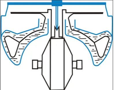
The first practical solution of Anschutz consists of strong electric motor hanging below the float which is dipped in the mercury. Additionally to the motor, the smart apparatus has been fixed for correcting the mass arrangement. This second apparatus has had shape of pendulum, which has been steered by air stream produced by spinning motor, which resulted in dumping the compass oscillations.
The fundamental feature of the Anschutz’ compass is the shifting of the centre of the mass of the gyroscopic element below its geometric center. It causes the directive force to aligning gyroscopic element in the proper direction. Anschutz’ competitor - Sperry in 1911 invented for it the communicating vessels with mercury. This solution gives it more flexible source of directive force, as variable level of the mercury generate the variable force, according to different latitude of the ship and
different deflection of the directional element out of the meridian. Sperry’s solution was so good, that has been applied up to the end of the XX century (Robertson RGC11 for example).
Around the 1925 Anschutz modified his one-gyro construction by introducing the well known two-gyro sphere (“New Anschutz”), which is the basis of the most popular modern gyrocompasses and we can observe only miniaturization of it. Before the Second World War it weighted about 200 kilos and needed some 2kWt of energy, when the modern one weight 20 kilos and need only 80Wt (for example Anschutz Standard series or Plath Navigat series). This is possible mainly because of the digitalization, so additionally it results in digital mode of transmission of the heading.
Common feature of any gyrocompasses designed after Anschutz or Sperry constructions is the internal source of directive force, which is originated from the distribution of the mass of sensitive element. So the most popular class of gyrocompasses could be named as gyrocompasses with internal correction.
The bad implications of this are dynamic deviations of the gyrocompass. New way of gyrocompasses’ development is the idea to influence on three degrees of freedom gyro from outside, for example by turning the gimbal circle with electrical engine. It can be steered by mathematical machine on the basis of information about the angle of elevation of the main axis of the free gyro over the horizon. This is
the idea of gyrocompass with external correction.
The examples of this group are Tokimec ES 110 or Russian Vega compasses. In such construction the directive force is calculated according to the place of the ship on the Earth, her speed and heading, and elevation of the main axis of the gyro over the horizon, measured by inclinometer. So lots of sources of deviation are eliminated and naturally the dynamical quality of presented heading is better than in case of gyrocompasses with internal sources of correction.
Regardless of what was mentioned before, as alteration of inertial systems the analytical compasses rise in the eighties of the last century. Although there are produced with mechanical, Single-Degree-Of-Freedom (SDF) gyros (for example Navistab), however mainly analytical compasses based on optical ones (for example Navigat 2100 or Raytheon MINS). Two fundamental laser gyroscope types are used: the ring laser gyroscope
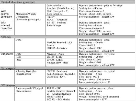
Table. 1. Comparison of different gyrocompasses
Dynamic performance – poor on fast ships Settling time – 4 hours
Cost – some thousands $ Weight – about 100kG or more Power consumption – at least 80W (Sperry)
Dynamic performance – good Settling time – 4 hours Cost – some thousands $ Weight – about 100kG or more Power consumption – at least 80W Analytical
DTG
Meridian Standard – SG Brown
SKR 82 –Robertson
Dynamic performance – good Settling time – ~20 min Cost – 10 000 $ Weight – about 100kG
Power consumption – at least 80W
Strapdown DTG Navistab – Plath Dynamic performance – very good Settling time – ~20 min
Cost – about 50 000 $ Weight – about 30kG
Power consumption – at least 80W
RLG LSR85 - LITEF
FOG LFK95 - LITEF
Navigat 2100 - Plath
Gyro-magnetic
Vibrating Gyro plus fluxgate sensor
SSC200 - Maretron Sonic Compass - Tecnautic GytoTrack - KVH
Dynamic performance – very good Settling time – ~5 min
Cost - about1 000 $
Weight – about 100G or more Power consumption – less 1W GPS compass
2 antennas and GPS signal phases measure
JLR 10 - JRC
Satellite Compass Standard 21 – Anschutz Rytheon HS 50 - Simrad MX 575 – MX Marine
Dynamic performance – excellant Settling time – ~5 min
Cost - about 5 000 $
Weight – no more 5kG (with antennas) Power consumption – 15W
Next kind of gyrocompasses is gyro-magnetic ones. The idea of combining the magnetic compass with gyroscope has been know from fifties. Such kind of devices has been utilized on airplanes and very fast war cutters (torpedo or missiles boats). Easy accessible “from the shelf” new magnetic sensors (fluxgate) and MEMS gyros establish the opportunity to build very sophisticated instrument. Generally speaking it is one, more often vibrating, gyro which is augmented by information from fluxgate sensor with magnetic direction, and with computer, as it is natural in the nowadays. So for price on the level of 1000Euro it is possible to buy gyrocompass with settling time of 5 minutes and weight much less than 1 kg! It has no dynamical deviations and is not influenced by any ship’s maneuver. At the moment this group of devices is treated as no-professional equipment, so it could be suggested for any yachts, fishing ships and so on. At the moment they have no approvals of classification societies but why it is so? May be the interest in the field of leisure fleet is so massive, that it is no interest to pay for receiving the certificate of approval? At the moment this device fulfills all
records of Convention for Safety of Life at Sea and IMO Resolution A.424, except for only one point – there it is not clear is it a gyrocompass or not.
3 SUMMARY
Nowadays gyrocompasses are a group of navigation systems, which include much differentiated devices. In the paper the main group of them has been presented as well as the most important facts about their designing and features.
The table presents the four brands of compasses which are used nowadays, and the most typical examples of each one.
Summarizing we can say, that the most popular at the moment are compasses with internal corrections, but they have the worst dynamical properties and they are relatively expensive. The other groups have at least the same accuracy or better, but they are free of dynamical deviations and they have shorter settling time.
The strapdown system is the most accurate and there is only one system which is able to measure three angles of ship attitude, but this is the most expensive one. In contrary, the gyro-magnetic one is
the cheapest one dimensional compass, but in common opinion it is fit for small vessel.
REFERENCES
Chatfield A.B., “Fundamentals of High Accuracy Inertial Navigation”. Progress in Astronautics and Aeronautics. Charles Stark Draper Laboratory, Inc. Cambridge, 1997. Ferry E.S., “Applied Gyrodynamics”. J. Willey and Sons, New
York 1933.
Grewal M.S., Weill L.R., Andrews A.P., “Global Positioning Systems, Inertial Navigation and Integration”, John Wiley & Sons, 2001.
Jekeli Ch., “Interial Navigation Systems with Geodetic Applications”. W. de Gruyter, 2001.
Lawrence A., “Modern Inertial Technology. Navigation, Guidance and Control”, Springer 2001.
“The Anschutz Gyro-Compass. History, description, Theory & Practical Use”. Elliott brothers, London 1910.