V
IENNA
U
NIVERSITY OF
T
ECHNOLOGY
Institut f ¨ur Technische Informatik
Technical Report 182-1/2007/70
Embedded Security at a Glance:
Security Concepts for Embedded Systems
Armin Wasicek
ii
iii
Copyright Notice
This report is copyrighted. The report may not be sold or used for com-mercial purposes, without prior written consent of the author. Requests for quantity or partly reprints, commercial use permits, or other inquiries should be directed to:
Armin Wasicek
Institute for Computer Engineering Treitlstrasse 3/3
1040 Vienna Austria
tel.:+43 1 58801 18211
iv
Abstract
Information security is gaining more and better attention from the embedded systems community. It is now widely acknowledged that security and safety are intrinsically tied and may not be torn apart during the design process. embedded systems often sustain a criti-cal infrastructure which is exposed to accidental as well as malicious faults. Acts of vandalism, terrorism, sabotage, or crime pose seri-ous threats to a system’s correct operation. In the face of pervasive computing embedded systems play a major role in distributing the computational power of modern microprocessors to business, trans-portation, governments, public space, and even households. Besides the benefits of this progress, the reverse side is that people may have different intentions and motivations to use the systems. By specify-ing security threats and counter measures durspecify-ing the system design it must be guaranteed that the embedded system may be utilized only in the way the designer intended, the user requires, and within the boundaries of regulations and legal obligations of the deployment area This report gives an introduction to information security un-der the aspect of embedded systems. It explains some general se-curity measures, summarizes cryptography and trusted computing, and points out the concepts of intrusion tolerance.
CONTENTS v
Contents
1 Introduction 1
1.1 Definitions of Security . . . 2
1.2 Terminology . . . 3
2 Embedded Systems Security 6 2.1 Attacks on Embedded Systems . . . 6
2.2 Design challenges for Embedded Systems . . . 8
2.3 Security Applications in Embedded Systems . . . 9
3 Common Security Techniques 11 3.1 Authentication . . . 11
3.2 Firewalls . . . 12
3.3 Intrusion detection . . . 13
3.4 Virtual Private Networks (VPN) . . . 15
4 Cryptography 17 4.1 Cryptanalysis and Security of Ciphers . . . 18
4.1.1 Threat models and attack modes . . . 19
4.2 Symmetric Cryptography . . . 21
4.3 Asymmetric Cryptography . . . 22
4.3.1 RSA Algorithm . . . 23
4.3.2 Elliptic Curve Cryptography (ECC) . . . 24
4.4 Computation . . . 25
5 Trusted Computing Platform (TCP) 28 5.1 Goals of the TCG . . . 29
5.2 TPM Specification Overview . . . 29
5.3 Related projects and implementations . . . 31
6 Physical Security 33 6.1 Tamper resistance . . . 33
6.2 Hardware measures . . . 34
6.3 Side–Channel Attacks . . . 35
6.3.1 Power Analysis . . . 36
7 Information Security Economics 39 7.1 Motivation . . . 39
7.2 Security Metrics . . . 39
CONTENTS vi
8 References 42
A Security Standards and Documents Overview 50 A.1 International Standardization Organization (ISO) . . . 50 A.2 Bundesamt f ¨ur Sicherheit in der Informationstechnik . . . . 50 A.3 Austria Secure Information Technology Center (A–SIT) . . . 51 A.4 Instrumentation, Systems, and Automation Society (ISA) . . 52 A.5 FIPS 140-2: Security Requirements for Cryptographic
Mod-ules . . . 52 A.6 Information Security Forum (ISF) . . . 53 A.7 Common Criteria (CC) . . . 53
B Primality Testing 55
C Chipset manufacturers and TPM functionality 57
D Acknowledgements 59
LIST OF FIGURES vii
List of Figures
1 Relationship between dependability and security after Aviˇzienis
et al. . . . 3
2 Fault model after [85]. . . . 3
3 Intrusion model after [66]. . . . 4
4 Vulnerability life cycle after Schneier [72]. . . . 4
5 Attacks on Embedded Systems after [69] . . . 7
6 Structure of a firewall element connecting a secure and an inse-cure network . . . 12
7 Block diagram of intrusion detection system . . . 14
8 Virtual network on top of a physical network. . . . 15
9 Cryptosystem: Principle of Operation . . . 17
10 Block diagram of a Trusted Platform Module (TPM) . . . 30
11 Tamper response modus operandi . . . 34
12 How aPUFcan be used as an uncloneable key. . . . 36
13 Setup for a power analysis attack . . . 37
LIST OF TABLES viii
List of Tables
1 Overview ofVPNprotocols used withIP. . . 16
2 Cyptographic modes . . . 22
3 Components of theRSAalgorithm . . . 23
4 PKCS standards . . . 24
5 NISTguidelines for the equivalent strengths of various cryp-tographic algorithms . . . 26
6 Supplied byNISTto ANSI X9F1 . . . 26
7 Average ECC and RSA execution times on the ATmega128 and the CC1010 after [32] . . . 27
Introduction 1
1
Introduction
With the raise of information processing technologies, digital data pro-cessing is penetrating many areas of everyday life and carrying out cru-cial duties and responsibilities. To guarantee the smooth operation, safety and security measures must deliver a correct and sound service. The im-portance and demand for information security is increasing equally to the demand for digital control.
In contrast to general–purpose computers, embedded systems are de-signed to perform a certain task. The term ’embedded’ implies that their operation is transparent for the user, who can be completely unaware of their deployment. Embedded systems emerge from the field of control engineering and are now deployed in many areas like transportation, in-dustry, communication, economy, infrastructure, etc. In order to achieve their goal, embedded systems have to act in anintelligentmanner.
An ITsystem’sassetis the value of its service to its users. This can be, e.g., a database serving some precious information. To protect this asset the database’s information must be kept secret, thus, it requires confiden-tiality. With embedded systems this is different, because the information has usually either short lifetime before it is consumed, or can be collected by everyone from the environment. The important thing is the functioning of the embedded system. Thus, an embedded system’s asset is to deliver an efficient and dependable service. This poses requirements on availabil-ityandintegrity. Together, these three attributes formsecurity[85].
Until today the embedded system design process focuses on achieving the attributes associated with dependability, but neglects the demand for security. Recently, the security requirements of embedded systems started to gain more attention by the scientific community. This is due to the achievements of pervasive computing, e.g., in the western world nearly everybody is carrying a cellular phone and thus a computer, the ambitious efforts to establish a digital marketplace, the emerging of an infotainment culture, . . . Governments grasp embedded systems as a means to enforce regulations and legal obligations, e.g., the digital tachograph system, pub-lic surveillance, . . . In the industrial field, a unifying network will merge enterprise level, information level, control level, and field level networks, catchwordIP instrumentation[58]. Among many more, these topics open new challenges and raise new issues concerning security.
com-1.1 Definitions of Security 2
putation on limited devices. Furthermore, the concepts of trusted comput-ing are discussed and the physical security properties of embedded de-vices are presented. Next, the concept of intrusion tolerance is explained and, finally, some ideas on the economics of security can be found the last section.
1.1
Definitions of Security
The term’information security’means protecting information and information systems from unauthorized access, use, disclosure, disruption, modification, or destruction in order to provide three core principles: confidentiality, integrity and availability.”1
• Confidentiality: The assets are accessible for reading, copying, locat-ing only by authorized parties. If secrecy is not maintained, the computer system is susceptible to unauthorized disclosure of data or unauthorized access to its programs.
• Integrity: The modification (writing, changing, changing status, delet-ing creatdelet-ing) of an asset requires authorization. The integrity require-ment does not hold, when an unauthorized user or program may modify data or damage the system.
• Availability: Authorized parties can access the assets in the manner specified and during the periods specified. Lack of availability re-sults in adenial–of–service.
In Figure 1 Aviˇzienis et al. [85] give a definition of security and de-pendability in the light of their shared and distinct attributes. Security is the concurrent existence of availability for authorized users only, confiden-tiality, and integrity regarding unauthorized manipulations of the system state. Authorizationis the right or permission to use a system resource. A
security policyis a definition what is secure and thus admissible, and which behavior is considered insecure and therefore prohibited.
Secondary attributes to security are composites of primary ones, i.e., they share the properties of two or more primary attributes to a certain degree. They include:
• Accountability: availability and integrity of the person who performed an action.
1.2 Terminology 3
Figure 1: Relationship between dependability and security after Aviˇzienis et al.
• Authenticity: integrity of a message content and origin, eventually including other types of information, e.g., time.
• Non–Repudiability: availability and integrity of the identity of a par-ticipant in the communication. The goal is it to provide irrefutable proof of an action in the system to a third party.
1.2
Terminology
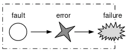
A basic terminology for security and dependability was developed during the MAFTIA project [66]. The cited document relates security breaches to the fault model described in [85]. It defines the causal triple fault–error– failure as follows:
• fault: adjudged or hypothesized cause of anerror.
• error: part of the system state which may cause a subsequentfailure.
• failure: occurs when the error reaches the service interface and the delivered service deviates from implementing its function.
fault error failure
Figure 2: Fault model after [85].
1.2 Terminology 4
intrusion error failure vulnerability
attack
hacker, designer, or operator
Figure 3:Intrusion model after [66].
An attack is is an attempt to to exploit a weakness or vulnerability in the system in order to perform an unauthorized action. A succesful attack attempt results in anintrusion. Figure 4 illustrates this relationship. It fur-ther suggests that a vulnerability can be introduced during development or operation by hackers, operators, and designers.
• attack: a malicious interaction fault respective an intrusion attempt which aims at deliberately violating one or more security properties.
• vulnerability: a fault deployed during operation or system design that can be exploited to create an intrusion.
• intrusion: an externally–induced fault resulting from an attack that can be used to alter the system state.
Theintrusion–toleranceparadigm is introduced in [80]. It assumes that systems remain to a certain extent vulnerable and that attacks on compo-nents or sub-systems will happen and some will be successful. Its goal is it to ensures that the overall system nevertheless remains secure and opera-tional, with a measurable probability. This is achieved by error processing mechanisms that make sure that a security failure is prevented.
discovery 1
2 announcement 3 popularity
4 patch available
5 patch applied
risk
time
1.2 Terminology 5
Embedded Systems Security 6
2
Embedded Systems Security
Three factors – also called theTrinity of Trouble– were identified to be the major source of vulnerabilities [37, 48].
• Complexity: Modern software is a complex clockwork of interacting components. With increasing functionality the code size grows as well. This increments the likelihood of bugs and vulnerabilities. Ad-ditionally, engineers program in unsafe languages like C and C++ where typing is rather weak and make use of insecure libraries which offer no protection against simple attacks like buffer–overflows [60] or dangling pointer errors.
• Extensibility: Today’s software is not a static piece of work, but con-stantly evolving. Updates and bug fixes change the codebase, elimi-nate existing vulnerabilities, and maybe open new ones. The article in [36] discusses the implications of patching software on security. Moreover, many operating systems for embedded systems support dynamically loadable device drivers and modules. Bugs shipped with these extensions may render the whole system vulnerable.
• Connectivity and remote usage of embedded devices increase their usability and open an incredible variety of possible applications, but unfortunately also give rise to network induced vulnerabilities. An attacker does not have to physically possess the embedded device, but can mount a remote attack. Furthermore, failure propagation among similar devices can cause massive security breaches [51], since there are more possible targets to attack, and attacks can be remotely managed.
In the case of embedded systems, a forth factor may be added, namely the operation in an untrusted environment. Many embedded devices have to stay secure even under the physical possession of non–trusted parties. Consider for example a not registered workshop for cars, loss or theft. A malicious person could try to physically break the system cryptographic boundary in order to access the device without permission. When embed-ded systems are used to implement regulations such as, e.g., road–pricing, they provide a very worthwhile target to crack.
2.1
Attacks on Embedded Systems
impor-2.1 Attacks on Embedded Systems 7
tant facts concerning this topic. Attacks can target either the design of an embedded device, hence the abstract model, or the real device thus its implementation.
Almost all known attacks on embedded systems are implementation attacks. They target to bypass or weaken the security functions. Theo-retically, the functional security mechanisms protecting the embedded sys-tem may satisfy the security requirements. In practice, the adversary will avoid a direct approach and try to circumvent the applied security mea-sures. Functional security mechanisms must be seen in contrast to their implementations, that offer more and new attack possibilities, which might not be obvious during system design, when security functions are consid-ered as ’black box’ building blocks. Hence, they are far from being com-plete security solutions and systems designed this way uncover a broad attack surface.
Integrity Attacks Privacy Attacks Availability Attacks
Electromagnetic
Figure 5: Attacks on Embedded Systems after [69]
Figure 5 is a reproduction of the threats listed in [69]. It divides attacks on embedded systems in two classes, a functional classification on the one hand, and anagent–based classificationon the other hand. Functional secu-rity mechanisms support the main attributes of secusecu-rity, e.g., an encryp-tion algorithm facilitates privacy, or a (secure) hash funcencryp-tion implements an integrity measure.
2.2 Design challenges for Embedded Systems 8
far the biggest threat to all kinds ofIT–systems, make use of, e.g., miscon-figuration or buffer–overflows to run malicious code like viruses, worms, or trojan horses. Typically, the infrastructure for software based types of attack is much cheaper and easier to acquire compared to physical attacks.
Physical attacks and side-channel attacks directly access the device, the board, or the embedded chips. They are either invasive, which means they physically intrude into the device, non-invasive, like some sorts of side-channel analysis, or a combination of both. The first category encompasses types of attacks like reading out memories (microprobing) and listening to inter–component communications (eavesdropping). The second category covers simple and differential power attacks (see Section 6.3), timing at-tacks, fault injection atat-tacks, and electromagnetic analysis.
2.2
Design challenges for Embedded Systems
The papers in [30, 69, 48] investigate design challenges for embedded sys-tems. Compared to standardIT–systems some gaps can be identified which point out the reasons why applying security measures to embedded sys-tems is a major challenge.
• Theprocessing gaphighlights that current embedded system architec-tures are not capable of keeping up with the computational demands of security processing.
• Thebattery gapemphasizes that the current energy consumption over-head of supporting security on battery constrained embedded sys-tems is very demanding.
• Theflexibilitystresses that an embedded system is often required to execute multiple and diverse security protocols and standards.
• Thetamper resistanceemphasizes that secure embedded systems may be facing an increasing number of attacks from physical to software attacks. Side–channel attacks also represent an important threat for these systems.
• Theassurance gapis related to reliability and stresses the fact that se-cure systems must continue to operate reliably despite attacks from intelligent adversaries who intentionally seek out undesirable failure modes.
2.3 Security Applications in Embedded Systems 9
decision in favor of security might require an additional chip and hence increase the overall system cost.
2.3
Security Applications in Embedded Systems
On the contrary to standardITsystems, which are mostly exposed only to remote attacks, an attacker of an embedded system mostly has the system physically under his control. This adds physical attack scenarios (side-channel attacks [48, 57, 75], reverse engineering, device tampering [56], etc.) to the range of possible attacks.
These scenarios in addition to the classical challenges, the ”Trinity of Trouble” are the reason for the big demand for security in embedded sys-tems. Several challenges can be identified for the near future [62]. To meet the challenges, security design must be considered right from the start.
• Software maintenance. Software is by nature ever–evolving and its development doesn’t stand still. Because many bugs are found af-ter shipment and requirements are changing, it has to be constantly adapted. To enable software maintenance a mechanisms to perform secure updates on an embedded device is mandatory. Updates and update mechanisms are the gate through which many malicious pieces of code try to slip on their vicious mission.
• Theft prevention: A device’s operation can be bound to an embedded security mechanism to restrict the usage to its legal owner. A well known–example for this is the electronic immobilizer – a remote con-trol key for opening cars and starting the engine. This challenge is often connected to the area of biometrics which aims at unambigu-ously identifying individuals.
• Access control: An embedded system’s operations and data should be protected from unauthorized access to ensure their responsible usage. In many applications embedded systems perform mission– critical tasks and human lives depend on their correct operation. Thus, a protection of these systems is necessary to avert the conse-quences of a security breach. The worst–case assumption in this case is a nuclear power plant in the hands of a terrorist.
2.3 Security Applications in Embedded Systems 10
currently emerging from the digital world. Security measures are a stakeholder in the functioning of this new marketplace.
• Personalization/identification: The genuine identification of the user supports the creation of user profiles, which can be used, e.g., to con-figure a car’s comfort functions to a driver’s customized settings, or to implement a logger similar to a flight data recorder (FDR), which records the users and the utilized functions of the device.
Common Security Techniques 11
3
Common Security Techniques
This section summarizes some common security techniques which can be found in many applications.
3.1
Authentication
An authentication procedure establishes a trust relation between two prin-cipals. One principal exhibits some sort of credentials which the other principal checks for validity. After a successful test the first principal is acknowledged to the second one who in return transfers some privileges to the authenticated principal.
A well–known application of authentication is access control. An em-bedded device is only operational after a successful authentication pro-cedure, e.g., entering a personal identification number (PIN) when using a cash machine or after powering a cellular phone. However, a common misconception is that a computer confirms the identity during authenti-cation. It is not possible to establish or prove an identity. The only thing which can be done is to perform a test which is considered as sufficient. Since the creation of such tests must take into account many factors like security and usability, it is not a simple task finding an adequate one.
In the following a short authentication method overview is given:
• Kerberos (GSSAPI)[49] is based on the Needham–Schroeder Symmet-ric Key Protocol. It includes a timestamp to fix the vulnerability of the original protocol to replay attacks. Two principals identify them-selves by the use of a trusted third party.
• The SSL/TLS handshake [26] is responsible for the ciphersuite nego-tiation, the initial key exchange, and the authentication of the two peers in theSSL/TLS protocol. It uses RSApublic key cryptography for authentication.
• SOCKSv5 [55]. This is a very simple method where a username and password combination is sent in plaintext to a server in order to re-quest its relay service.
3.2 Firewalls 12
3.2
Firewalls
A security policy determines a computer system’s access restrictions. More specifically it states who may access what in which manner. A firewall enforces the access controls. From a system designer’s point of view, a firewall isnot a single device or a group of devices, but the implementation of a security policy.
As a perimeter firewall a firewall acts as a special gateway extending a normal gateway for communication control features. It can allow or deny inbound or outbound communication requests and thus govern access to a network. A policy defines how access is granted among users, which usually consists of several rules. Message filtering has to be performed according to these rules. In the distributed case [15], several single fire-walls are grouped in a virtual private network (see Section 3.4) to execute a common policy.
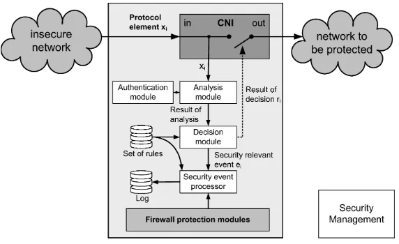
Figure 6: Structure of a firewall element connecting a secure and an insecure network
The basic architecture of a firewall implementation is depicted in Fig-ure 6. A protocol element xi arriving from an non–trusted network is
tapped and forwarded to an analysis module, which checks for validity and authenticity or defrags several coherent elements. Based on a set of rules forming the security policy a decision is taken, either to accept the protocol element in the protected network or to trigger a security relevant event.
3.3 Intrusion detection 13
a new node or a new service to the cluster, or through the occurrence of a certain system event. An interface must be provided to reconfigure the working rule set efficiently, secure, and without message loss.
Firewalls present an efficient tool to control access to a network, but they also have some restrictions, one has to be aware of following threats when deploying a firewall [10, 14]:
• Insidersare a major threat. A firewall can prevent users from outside the network accessing it and users from the inside to leak informa-tion, but it can do nothing about attacks carried out from inside the network. This is only partly true for a distributed solution.
• Hidden channels are communication channels from and to the net-work which are not monitored by the firewall. Therefore, they are not part of the security concept.
• Restricted design: A firewall can only avert threats for which it is de-signed. It can be vulnerable to new modes of attack.
• Malicious logic (e.g., viruses, worms) delivered within the message body cannot be recognized by simple firewalls, because most of the filtering is based on communication protocol elements.
• Tunneling is encapsulating one communication protocol inside an-other one. This technique is used to transport a network protocol through a network which would otherwise not support it, or to pro-vide various types of a virtual private network (VPN) functionality. It can also be used to bypass a firewall system. In this case, firewall-blocked data is encapsulated inside a commonly allowed protocol. Again, this is only partly true for a distributed solution.
3.3
Intrusion detection
Adopting the definition worked out during the MAFTIA [66] project,
in-trusion detection concerns the set of practices and mechanisms used towards detecting errors that may lead to security failure, and/or diagnosing attacks.
3.3 Intrusion detection 14
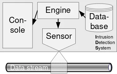
with the capability to react on certain recognized events. Figure 7 depicts the basic block diagram of an IDS; a sensor taps a data stream, forwards the data to an analyzing engine, which might make use of a signature database, and a console for user interaction.
Sensor
Figure 7: Block diagram of intrusion detection system
The detection of attacks on computer systems is to perceive the dif-ference between a system’s normal or expected behavior including error system states and the behavior if the system is under attack. Two cate-gories of techniques exist with which the observed system is compared:
Anomaly–detection techniquescompare the observed system against normal usage profiles andMisuse–detection techniquescheck for activity profiles vi-olating the system’s security policy.
After [33], intrusion detection may be accomplished
• after the fact (post–mortem audit analysis),
• in near real–time, or
• in real–time (in support of automated countermeasures).
3.4 Virtual Private Networks (VPN) 15
3.4
Virtual Private Networks (VPN)
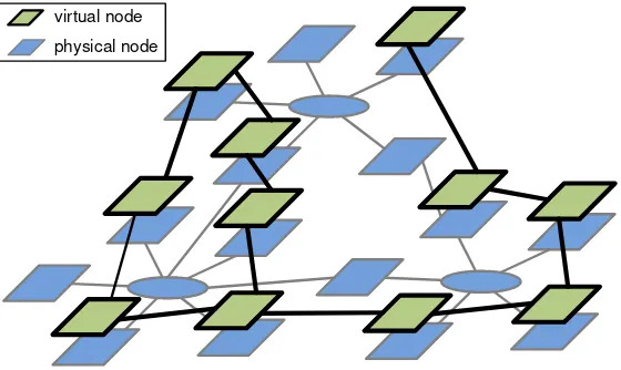
Avirtual networklinks its nodes in a way that the underlying physical net-work must not correspond to the virtual connections between nodes. To the user a virtual network appears as one large network, whereas physi-cally it may incorporate several networks or parts of networks. Further-more, a virtual private network (VPN) provides a privacy service for these virtual communication lines. VPNs are mostly configured within large public networks like the Internet, in order to virtually create local area networks (LANs) which span large geographic areas.
Secure connections over insecure networks are implemented by wrap-ping an insecure protocol in a secure protocol. This technique of encapsu-lation is calledtunneling. For example, the Internet Protocol’s (IP) packets are transmitted in plaintext. By embedding anIP packet as payload data into its secure counterpart IPSec, an regular IP connection can be made secure transparently to the user.
The three core services a VPN must facilitate areauthentication, encryp-tion, andvalidation. More specifically, sender authentication is required for access control and to counter identity spoofing, data confidentiality is op-tional and established by encryption and blocking packet snooping and sniffing, and, finally, message integrity measures provide validation and mitigate message alteration.
Table 1 gives an overview of some widely used VPN protocols with IP. Figure 8 shows the layering of a virtual network on top of a physical network. The wiring is drawn arbitrary.
virtual node physical node
3.4 Virtual Private Networks (VPN) 16
NAME DESCRIPTION REF.
IPSec (IP security)
The security extension for IP. Comes in two flavors: authentication header (AH) support sender authenti-cation and message integrity; encapsulated security payload (ESP) implements all three core services. It is implemented at the transport layer in theOSImodel.
[44]
OpenVPN This open source VPN is based on the SSL/TLS net-work stack for secure communication and resides on the application layer. The advantage of this approach is that no radical changes have to be made to the oper-ating system’s network stack and the SSL/TLS can be run on virtually any client.
[28]
PPTP The Point–to–Point Tunneling Protocol was devel-oped jointly by a number of companies, including Mi-crosoft. Its popularity is due to the fact that is was the firstVPNshipped with Microsoft Windows and its easy configuration.
[34]
L2TP The Layer 2 Tunneling Protocol was derived from the PPTP protocol. It does not include encryption, but is often used in conjunction with IPSec. A point–to– point protocolPPPis assumed on the underlying layer.
[64]
L2TPv3 The Layer 2 Tunneling Protocol version 3 is a new re-lease.
[54]
Cryptography 17
4
Cryptography
The basic terminology [4] is thatcryptographyis the science and art to de-sign ciphers; cryptanalysisis the science and art of breaking them; cryptol-ogyis the study of both. Cryptography provides the tools, which underlie most modern security protocols. A cryptographic scheme or cryptographic systemencompasses one or more cryptographic algorithms (ciphers), pro-tocols, data processing and storage facilities, and its users. Basically, any computer system that involves cryptography is called a cryptosystem2.
Because of this, breaking a cryptosystem is not restricted to breaking the underlying cryptographic algorithms. Usually it is far easier to break the system as a whole through finding the weakest link in the system, which is usually not the cryptography.
The ultimate goal of cryptology is hiding information from others. In basic scenario, a sender transmits a message to a receiver and doesn’t want anybody else to read the message. For this purpose, the relevant piece of information is encoded by the sender with some cryptographic algorithm, transported over a medium, and then again decoded at the receiver. To prevent a third party to read out the message from the medium in plain-text, but to grant access to the message’s information to the appointed receiver, some kind of asymmetry has to be introduced between those two kinds of parties. In most cryptographic algorithms this asymmetry is in-troduced by some shared secret only known the sender and the receiver, e.g., a password or a numeric key. The security of a cryptosystem thus depends on the concealment of the secret.
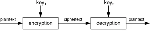
Figure 9 sketches a cryptosystem’s basic principle of operation: A plain-textis used as input for a black box cryptosystem, which then performs an
encryptionoperation under key1 and it yields aciphertext as output. Con-sequently, the ciphertext can be deciphered by adecryptionoperation with
key1, whose output is the input plaintext from the start.
plaintext plaintext
encryption decryption
key1 key2
ciphertext
Figure 9: Cryptosystem: Principle of Operation
2Note that in the context of cryptography,cryptosystemrefers to a suite of algorithms
4.1 Cryptanalysis and Security of Ciphers 18
There are two major classes of algorithms in cryptography, namely private-key or symmetric algorithms and public-key or asymmetric algo-rithms. If encryption and decryption operation are performed using the same key (key1 =key2), the operation is symmetric, if both keys are dis-tinct (key1 6=key2), the operation is called asymmetric. An analogy for symmetric schemes is a safe box with a lock: everybody holding the key can open the box and deposit messages inside or retrieve messages from the box. An asymmetric scheme extends this analogy by making a slot in the box (hence a letter box): everybody can insert messages through the slot in the box, but only the receiver can open the box and get his messages out [83].
Tutorials on cryptography can be found on every corner of the Internet and nearly every text book on security has also a chapter on cryptography [4, 17, 18]. The classic book on cryptography is written by Bruce Schneier [73]. The papers in [83] highlight cryptography in the context of embedded systems.
The remainder of this chapter is organized in four chapters. Firstly, some generic attack modes on ciphers are discussed. Next, a short intro-duction on the two kinds of cryptography, asymmetric and symmetric, is given. The last chapter presents some implementation issues, computa-tion of cryptographic algorithms, and performance measurements.
4.1
Cryptanalysis and Security of Ciphers
An attack on a cryptosystem aims at revealing the concealed information without prior knowledge of the secret key. This challenge can be met by exploiting certain properties of the encryption or decryption operation. Note that this section presents attacks on the cipher directly. In crypto-graphic schemes there exist other possibilities like, e.g., power analysis (see Section 6.3) to break the scheme. The most simple method to break a cipher is through guessing or (randomly) probing all possible keys. This attack mode is referred to asBrute–Force–Attack. The size of the key space determines the worst case assumption for the number of guesses, till one is successful. More sophisticated attacks try to narrow the key space by eliminating some of its portions or by improving the way the guesses are selected.
A cipher’s security can be defined as a function of thealgorithm’s strength
4.1 Cryptanalysis and Security of Ciphers 19
of two operations, generating a guess and checking it by a test. Conse-quently, the worst case execution time is for a Brute–Force–Attack the size of the key space multiplied by the duration of key generation plus a sub-sequent check. Modern cryptosystems have key spaces larger than the number of atoms in the universe3and the computation of a Brute–Force–
Attacks could last longer than the universe’s expected lifetime4.
Never-theless longer key length can have a positive impact on a cryptosystem’s security, the system should still remain usable; handling key sizes of some kilobyte can be cumbersome and even insecure. Brute–Force–Attacks can usually be highly parallelized by partitioning the key space and thus re-duce the time spent for breaking the cipher by a constant factor. This intro-duces a forth aspect of security, besides strength, key length, and time to break, namelycost. This aspects relates to the cost of a machine’s computa-tion time (acquisicomputa-tion cost and operating cost) and the number of machines needed to deploy the attack. Implementations of highly parallelized dis-tributed cracking machines range from special hardware supercomputers on the one hand [82], to workstations connected to the Internet and or-chestrated by software using the computer’s idle time on the other hand [1].
So how can a cipher be kept secure? It has been widely acknowledged, that concealing the details of the algorithm is never secure. There is no such thing as ”security by obscurity”. The only way to assure oneself of a cipher’s strength is to submit it for a public review process. The more experts take a look on the cipher, the higher the probability it is secure. For example, the new Advanced Encryption Standard (AES) has been selected by theNISTafter a three year period of public test out of five candidates.
The remainder of this chapter introduces common threat models to ci-phers, symmetric and asymmetric cryptography, and, finally, it discusses some performance related issues. Please note that most applications use hybrid cryptosystems, a conjunction of both symmetric and asymmetric cryptography in order to achieve security and performance. The latter criteria is especially important, because the cryptosystem will fail, if it is delaying the user from doing his work..
4.1.1 Threat models and attack modes
In Bruce Schneier’s book [73], four primary and three secondary cryptan-alytic attack modes are distinguished:
3Which is around1080in the observable universe. 4Which ranges between1060ande10
50
4.1 Cryptanalysis and Security of Ciphers 20
1. Ciphertext–only. The attacker has access to a set of ciphertexts, en-crypted with the same cipher. His task is it to find out the corre-sponding plaintexts, or – even better – the secret key. This is a stan-dard scenario of an attacker eavesdropping a communication chan-nel.
2. Known–plaintext.The attacker has access to a set of cipher texts and their corresponding plaintexts. His task is it to find out the secret key or an algorithm to decrypt further messages, which have been encrypted with the same key.
3. Chosen–plaintext. The attacker has access to a set of cipher texts and can produce their corresponding plaintexts, e.g., he has a cryp-tographic device and can input arbitrary plaintexts and read the de-vice’s output. His task is it to find out the secret key or an algorithm to decrypt messages, which have been encrypted with the same key, i.e., find a way to duplicate the device.
4. Adaptive–chosen–plaintext. This method is similar to the chosen– plaintext attack mode, but the attacker can as well vary the subse-quently used plaintexts based on the information from the previous encryptions.
5. Chosen–ciphertext. The attacker has access to a set of ciphertexts, can decrypt them without knowing the key, and retrieve the output plaintexts. Sometimes this is called the ”lunchtime” or ”midnight” attack, where an attacker gains access to an unattended decryption machine.
6. Chosen–key. The attacker can make use of some knowledge about different used keys in the cryptosystem. This is a rather uncommon attack mode.
7. Using violence. Also called ”rubber-hose cryptanalysis”, this attack is exploiting the human factor and addresses all methods involving physical violence, blackmailing, kidnapping, threatening, corrupt-ing, and taking advantage of someone. In most cases, this is the most effective method.
4.2 Symmetric Cryptography 21
The attacker eavesdrops messages on the network. He fails to mount a successful ciphertext–only attack. So he decides to try a chosen–ciphertext by circumventing some authentication mechanism on the central server. He succeeds and ends up with a set of plaintexts and ciphertexts, which he can use again for a chosen–plaintext attack, or – if he can repeatedly access the server — an adaptive–chosen–plaintext attack.
4.2
Symmetric Cryptography
Symmetric cryptography [53] provides the ability to securely and confi-dentially exchange messages between two parties. As mentioned before in symmetric cryptography one key is used to encrypt and decrypt a mes-sage. This key represents a shared secret between the participants and every participant has a copy of the key. The inverse encryption function corresponds to the decryption function. There are two modes of opera-tion, block ciphers and stream ciphers. The former take a chunk of bits for encryption, the latter operate bit wise.
According to Shannon [77], two complementary concepts can be used to conceal information, namely confusion, which is making each output depend upon the key, anddiffusion, which is each output depend on each of the previous bits input. In block ciphers confusion is understood as substitution (replacing bits), and diffusion is understood as transposition or permutation (changing a bit’s position in the block). These functions are implemented as so–called S–boxes and P–boxes, which are aligned and connected in certain ways forming the cipher. The key serves as driver for the boxes. An attacker could assemble the same arrangement of boxes, but without knowledge of the key the boxes don’t uncover the secret.
Stream ciphers operate on a stream of digits and encode or decode each digit depending on the current state of the algorithm. Thus, the encod-ing of one digit depends on last encoded digit. Durencod-ing that process a se-quence of pseudo-random numbers (keys) is applied to a data sese-quence. This pseudo-random property makes the algorithm vulnerable to attacks. Ideally, a stream of truly random numbers is used like proposed for the one-time pad; but if there is no way to reproduce the key stream, there is no way to decode the data stream. An application field for stream ciphers are secure wireless connections, e.g., antenna Pay–TV or mobile commu-nication.
4.3 Asymmetric Cryptography 22
modus should not mitigate its strength, or even cause a vulnerability. On the other side, a well-chosen modus can improve a scheme’s security. Ta-ble 4.2 lists some modes mainly for block and stream ciphers.
Electronic Codebook (ECB)
A block of plaintext has exactly one corresponding ci-phertext. Each block of plaintext is encrypted separately. Like in a lookup table, every input has the same output assuming the same key.
Cipher Block Chaining (CBC)
A feedback loop is introduced: the plaintext of one block is XORed with the ciphertext of the previous block. The decryption operation works vice versa. The important part is to choose a secure first block to start with, the so–called Initialization Vector (IV). Two identical plain-text messages map to two different cipherplain-text messages, if two differentIVs are used.
Cipher Feedback Modus (CFB)
This modus is very similar to theCBCmode. The cipher-text of the previous block is fed back, encrypted again, andXORed with the current block. Actually the plaintext does not pass the encryption operation. Starting with an IV, a stream of pseudo–random bits is generated which is interweaved with the plaintext. This mode enables a block cipher to work as a self-synchronizing stream ci-pher.
Output Feedback Modus (OFB)
This mode enables a block cipher to work as a syn-chronous stream cipher. It works similarly to the CFB mode, but the result of the encryption operation is fed back, not the entire ciphertext. Consequently, a stream of infinite length could be produced. On the contrary inCFBmode, the algorithm blocks until the result of the XORoperation is available.
Table 2: Cyptographic modes
4.3
Asymmetric Cryptography
4.3 Asymmetric Cryptography 23
a secret. A drawback is that the computation of an asymmetric algorithm is more resource intensive compared to a symmetric one.
The security of asymmetric cryptography is that a specific mathemati-cally problem can be solved by someone having a hint (the key) easily, but it is unsolvable for someone who doesn’t have the hint. In the following some problems which are suitable for this purpose:
• The factorization of large integers is the task to compute an integer’s prime factors. If the number is composed by large integer primes this computation is currently unsolvable with public known algorithms. The bottleneck operation of every known factorization algorithm is performing primality testing (see Appendix B). If there would be a fast method to compute prime numbers, this would break the se-curity. of factorization–based cryptography (among several other things).
• The discrete logarithm problem exploits the fact that there is no effi-cient algorithm for computing discrete logarithms, while the inverse problem of discrete exponentiation can be computed efficiently, e.g., by using exponentiation by squaring, for example. The discrete loga-rithm problem applies to finite fields (Diffie–Hellman andDSA, see [27]) and to arbitrary groups, which is the motivating problem for Elliptic Curve Cryptography (ECC).
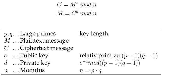
4.3.1 RSA Algorithm
The most important operation for the RSA cipher is the modular
exponen-tiationand represents solving the equations for encryption (1) and for de-cryption (2):
C =Me mod n (1)
M =Cdmod n (2)
p, q. . . Large primes key length
M . . . Plaintext message
C . . . Ciphertext message
e . . . Public key relativ prim zu(p−1)(q−1)
d . . . Private key e−1mod((p−1)(q−1)) n . . . Modulus n=p·q
4.3 Asymmetric Cryptography 24
Two large primes (p, q) are used to make a public-key/private-key pair (eandd) and the modulus n. Since nis part of the public key, everybody who can factorize n will be able to recompute d. So the security of RSA is based on the mathematical problem of factorization. A more detailed description of the algorithm can be found in [73].
Due to the political problems concerning cryptography in the United States, there is no standard available from the ANSI. Nevertheless, RSA Security, Inc., published some defacto standards addressing RSA crypto systems.
These Public Key Cryptography Standards (PKCS) can be downloaded from the company’s website5. Table 4.3.1 gives an overview of the different
standards. They contain a specification to build public key cryptographic schemes, i.e., a combination of the basic RSA operation, data structures, and a padding scheme. This is necessary to overcome different attacks on the basic RSA operation, which might result from weak keys, chosen plaintext, or chosen ciphertext attacks.
PKCS # 1: RSA Cryptography Standard
PKCS # 3: Diffie-Hellman Key Agreement Standard PKCS # 5: Password-Based Cryptography Standard PKCS # 6: Extended-Certificate Syntax Standard PKCS # 7: Cryptographic Message Syntax Standard PKCS # 8: Private-Key Information Syntax Standard PKCS # 9: Selected Attribute Types
PKCS #10: Certification Request Syntax Standard PKCS #11: Cryptographic Token Interface Standard
PKCS #12: Personal Information Exchange Syntax Standard PKCS #13: Elliptic Curve Cryptography Standard
PKCS #15: Cryptographic Token Information Format Standard
Table 4: PKCSstandards
The PKCS are as well part of other standardization initiatives, several RFCs have been published using thePKCS as a foundation [43, 41, 42, 59].
4.3.2 Elliptic Curve Cryptography (ECC)
ECCcryptography relies on the difficulty of solving the Elliptic Curve Dis-crete Logarithm Problem (ECDLP), that is defined on elliptic curves over finite fields Fm
p forming a group. They have a finite number of points,
4.4 Computation 25
and their arithmetic involves no round off error. Elements of the fieldFm p
are m–bit strings (vectors). The rules for arithmetic inFm
p can be defined
by either polynomial representation or by optimal normal basis represen-tation 6 SinceFm
2 operates on bit strings, its arithmetic computations are well–suited for computers.
Scalar point multiplicationis the main cryptographic operation and con-sists of the rudimentary operationspoint additionandpoint doublingon el-liptic curves over finite fields. The discrete logarithm problem is to com-pute the scalar k in P = kQ (with P, Q ǫ Fm
p ). The elements of a group
overFm
2 can be computed by a generating elementG, a so–called
genera-tor. In a cryptosystem, parametermdefines the key length and it must be chosen large enough (e.g.,m= 163), to prevent the efficient generation of a table of elements. By the use of an element table, the discrete logarithm problem can be solved by a simple table lookup. An asymmetric key pair consists of a random number k, which serves as the private key, and a corresponding public key computed bykG.
This computational asymmetry represents the cryptographic primitive which is used to create public–key schemes. Schemes are available for message signature (ECDSA, ECPVS, ECNR), encryption (ECIES), and key agreement (ECMQV, ECDH). The Standards for Efficient Cryptography Group (SECG) published an important standard referencing EC–based al-gorithms in [23, 24].
The smaller keys sizes used inECC cryptography result in faster com-putations, lower power consumption, as well as memory and bandwidth savings.
An interesting tutorial on the mathematics of elliptic curves among lots of other useful information can be found at Certicom’s website7.
4.4
Computation
Summarizing, the rudimentary operations executed by a CPUto compute an asymmetric cipher are modular exponention, modular multiplication, point addition, and point doubling. For symmetric ciphers, the atomic op-erations are bit–shuffling for permutation or P–boxes, simple non–linear functions for substitution or S-boxes, and linear mixing usingXOR. These operations bear the main load of cryptographic computation. Even a slight improvement in one operation can improve a cryptosystem’s overall
per-6While optimal normal basis multiplication is less insightful than polynomial
multi-plication, it is in practice much more efficient.
4.4 Computation 26
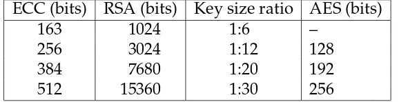
ECC (bits) RSA (bits) Key size ratio AES (bits)
163 1024 1:6 –
256 3024 1:12 128
384 7680 1:20 192
512 15360 1:30 256
Table 5: NIST guidelines for the equivalent strengths of various crypto-graphic algorithms
8-bit micro controller RSA-1024 ECC-160 Intel 8051 (14.75 MHz) 105s 4.6s 20x
Atmel AVR (4 Mhz) 22s 1.62s 14x
Table 6: Supplied byNISTto ANSI X9F1
formance tremendously.
The paper in [45] provides an overview of many modular exponention and modular multiplication methods. The most well–known algorithm is called the binary method or square and multiply method, and dates back to antiquity.
An efficient implementation for point multiplications uses a discrete Fourier transform (DFT) based method originally proposed for integer mul-tiplication. The article in [9] proposes to use number theoretic transform (NTT), which is found in many digital signal processing applications and because DFTfalls short in case of small integers as used for ECC cryptog-raphy (uses e.g., 163 bit integers).
Finally some collected performance statistics and reference material. Table 5 shows that ECC key sizes scale linearly, whereas RSA does not. This shows that future security requirements for strong cryptography can be computed with less power by the ECC. This table is widely cited and can be used reliably for a comparison between the different cryptographic schemes [31].
In Table 6 implementations for RSA and ECC are compared for 8-bit architectures. The results show, that theECC performs 20 times faster for the Intel 8051 and 14 times faster for the Atmel AVR. This information is taken from a Sun presentation available on the Internet8. If put in relation with the expected growth in key length in Table 5, the advantage of the ECCover theRSAis even more obvious.
At last a reference to a rock solid comparison study ofRSAandECCfor
8http://research.sun.com/sunlabsday/docs.2004/talks/2.03_
4.4 Computation 27
Algorithm ATmega128 @ 8MHz CC1010 @ 14.7456MHz time data mem code time data mem code
s bytes bytes s ext+int, bytes bytes ECC secp160r1 0.81s 282 3682 4.58s 180+86 2166 ECC secp192r1 1.24s 336 3979 7.56s 216+102 2152 ECC secp224r1 2.19s 422 4812 11.98s 259+114 2214 Mod. exp. 512 5.37s 328 1071 53.33s 321+71 764 RSA-1024 public-key e = 216 + 1 0.43s 542 1073 >4.48s
RSA-1024 private-key w. CRT 10.99s 930 6292 ∼106.66s
RSA-2048 public-key e = 216 + 1 1.94s 1332 2854 RSA-2048 private-key w. CRT 83.26s 1853 7736
Table 7: Average ECC and RSA execution times on the ATmega128 and the CC1010 after [32]
Trusted Computing Platform (TCP) 28
5
Trusted Computing Platform (TCP)
”The Trusted Computing Group (TCG) is a not–for–profit organization formed to develop, define, and promote open standards for hardware-enabled trusted computing and security technologies, including hardware build-ing blocks and software interfaces, across multiple platforms, peripherals, and devices. TCG specifications will enable more secure computing en-vironments without compromising functional integrity, privacy, or indi-vidual rights. The primary goal is to help users protect their information assets (data, passwords, keys, etc.) from compromise due to external soft-ware attack and physical theft.”9
The TCP is a consortium of about 170 companies from the IT busi-ness, incorporating many big players. Corporations like AMD, Hewlett– Packard,IBM, Infineon, Intel, Lenovo, Microsoft, Sun, etc. put a joint effort in developing open industry–wide specifications for trusted computing across multiple platform types. The range of specifications covers:
• Infrastructure Specifications
• Mobile Phone Specifications
• PC Client Specifications
• Server Specific Specifications
• Storage Specifications
• Trusted Network Connect (TNC) Specifications
• Trusted Platform Module (TPM) Specifications
• TPM Software Stack (TSS) Specifications
However, this endeavor is controversial. In the beginning, theTCGhas been critized because of its original motivation to establish digital rights management (DRM) and to prevent people from running unlicensed soft-ware, which is a rather economical intention under the sheepskin of user security. One main criticism was that the specification formerly known as TCPA takes away control from the user and gives it to the software and hardware selling companies. Nowadays, the biggest concerns are remote censorship and blacklists of computers. Many experts published articles on the web [78, 5, 74] discussing the benefits and dangers of the workings of theTCG.
5.1 Goals of the TCG 29
5.1
Goals of the TCG
The TCGstates four goals of trusted computing. Please note that the em-phasis is on ’trusted’ and not on ’secure’:
• Attestation: Proving the system’s integrity (data and programs) and validation of the platform to third parties. This is necessary to prove the system’s identity to others. Based on one root key, it introduces platform identity aliases, that may be associated with information relating to a specific use or domain.
• Sealing is the binding of data to the system configuration. Data is stored encrypted with a corresponding value of the system configu-ration. It may be unsealed, only if the original system state can be verified. Consider for example some encrypted data stored together with a hashsum of the encryption/decryption algorithm to guaran-tee its implementation has not been corrupted. Or some multimedia data stored together with a hash sum of a certain codec to ensure it can only be played by the software intended by the provider.
• Secure storage of cryptographic keys. Provide a secure storage for sensitive information. This encompasses space for a unique platform identification key and several derived keys. Generally, theTCG spec-ifiesmigrateable andnon–migrateablekeys, i.e., key–pairs which may leave theTPM, and keys which don’t.
• To provide secure cryptographic primitives like random number gen-erator, hash function calculator, etc. in hardware. Cryptosystems implemented in software can be insecure for two reasons, they can be replaced or circumvented or the processed keys can be tapped, e.g., by power analysis attacks.
5.2
TPM Specification Overview
5.2 TPM Specification Overview 30
Figure 10:Block diagram of a Trusted Platform Module (TPM)
The schematic view of aTPMis depicted in Figure 10. ATPMconsists of following components:
• The RSA engineis a hardware implementation of the RSA algorithm (see Section 4.3.1), which supports 512, 1024, 2048 bit keys.
• The RSA key generator generates public/private key pairs. Mostly used for temporary session keys.
• TheSHA–1 engineis a cryptographic primitive used by theTPMas its trusted hash algorithm.
• Thehardware random number generatorprovides a source of true ran-dom numbers. This is for the nonce used in cryptographic protocols, key generation, etc.
• Opt–in/outUser can decide whether or not he wants to enable or dis-able TPM functions.
• Execution Engineperforms the coordination of the TPM. It processes incoming requests and controls the other on–chip peripherals.
• The local I/O manages the communication from and to the device. Typically a Low PinCount Bus (LPC) is used.
• Volatile storage: To use a key it has to be loaded into theTPM. This is the location where session keys or external keys are stored for oper-ation. The second purpose is to store integrity measurements in the so–called Platform Configuration Registers acpcr.
5.3 Related projects and implementations 31
ATPM’sroot–of–trustemerges from two keys, theEndorsement key(EK) which provides a unique platform identity and is physically bound to the TPMdevice, and theStorage Root Key(SRK) managing the on–chip key stor-age. The SRKis a 2048 bitRSAS key and is the top level element – the root – of the TPMkey hierarchy. This key is recreated with each ”TakeOwner-ship” operation, which binds aTPMto a particular user. Other keys stored in theTPMare encrypted with the public part of theSRKwhen transferred to the outside. Thus, they are useless without the TPM, which encrypted them. For usage, they have to be loaded onto the TPM, where the corre-sponding branch of the key chain is rebuilt. This forms a Root of Trust, which is a ”hardware or software mechanism one implicitly trusts.” A set of storage keys for different purposes are wrapped by the Root of Trust.
The TPM implements the concept of transitive trust; during initializa-tion, a trusted component checks the next component to initialize. Hence, a tree of trust emerges with the initially trusted component as its root of trust. The steps to be taken are (a) compute the hash value of the next en-tity, check for correctness, and, if successful, pass control to the measured entity. This process starts with theBIOS initialization up to user level ap-plications. This way the system can be forced by the operating system to execute only trusted applications. Because aTPM is a slave device which monitors and checks the system, it cannot alter itself the execution flow of the system.
TPMs are designed to be relatively low cost devices that is important for market acceptance. They provide only limited resistance against so-phisticated hardware attacks, that is not perfect security, but better than a pure software solution.
5.3
Related projects and implementations
In order to comply with the specifications of the TCG, chipmakers have developed varying implementations that integrate theTPMfunctions into a normal chipset. See Section C for an overview of names and short de-scriptions.
The usual approach is to build a secure part of the operation system on top of theTPM. Most security critical operations are then performed in this secure system partition. The hardware guarantees that information flows only from the secure (or trusted) partition to the non–trusted partitions. A similar security pattern was firstly published as theBell–LaPadula Model
5.3 Related projects and implementations 32
lower levels (no write–down). In order to pass information below it must be
declassified, e.g., encrypted. The key again is stored with a higher security level than the message. Hence, the encrypted message can be read only from subjects belonging to the key’s security level, but may be delivered by a subject from a lower level.
Microsoft’s initiative is called Next Generation Secure Computing Base (NGSCB, formerly Palladium). NGSCB consists of a security kernel called theNexusthat is part of the operation system, andNexus Computing Agents
(NCAs), which are trusted software agents invoked by the applications and interfacing the Nexus.
Physical Security 33
6
Physical Security
In an embedded system two sub–fields of security merge, on the one hand
physical security which is concerned with preventing or deterring attack-ers from accessing a facility, resource, or information stored on physical media, and on the other handinformation securitywhich is protecting pro-grams and data against unauthorized access or modification, whether in storage, processing, or transit, and against denial of service to authorized users.
Section 2 lists several properties of embedded systems and stresses that they require to stay operational and secure even in an untrusted environ-ment. Consequently, they can not always trust their users or operators. Attackers may try, e.g., to seek out failure modes, weak default values, or simply use brute force in order to gain illegal access to information stored on the device or to operate the device offside it’s specification.
The remainder of this section first introduces the terminology on tam-per resistance. Next it presents some hardware security measures. Finally, it focuses on physical and side–channel attacks. These types of attacks refer to attack modes, which use physical properties of the embedded sys-tem. They can be further classified into invasive (e.g. microprobing, re-verse engineering) and non–invasive attacks (e.g. timing or power anal-ysis). Often, attackers take a combined approach, in the first phase they collect information during an invasive attack, which is then used to de-sign a non–invasive attack.
6.1
Tamper resistance
Tamper resistance [56, 70] is concerned with protecting devices from un-wanted physical access. On the contrary to side channel attacks (see Sec-tion 6.3), which is a passive, physical implementaSec-tion attack, device tam-pering is an active, physical attack, executed to gain access to device inter-nals like the bus subsystem, I/O pins, or even CPU registers. Some basic design principles for building tamper–resistant devices can be found in [50].
6.2 Hardware measures 34
can be taken, or, if the attack is over,attack recoverymust be facilitated and a secure system state has to be recovered. To notice that an attack has occurred, measures to provide evidence are necessary to establish.
Attack
Figure 11:Tamper response modus operandi
According to [56], devices can be aware of tampering in three ways:
• Tamper–evident characteristicsis to provide evidence that an attack has been attempted. This is achieved by applying security seals, using special covers, or enclosures, thus, something breaks when tamper-ing to prove the act to an authority.
• Tamper-resistant characteristicsis to provide passive physical protec-tion against an attack. Chip–design measures include the encrypprotec-tion of internal bus lines and memories which contain critical persistent data. Moreover, the layout should contain special characteristics, such as scrambling of bus lines and memories as well as special logic styles [56]. If an attacker manages to successfully tamper the device, he can get only useless information out of it.
• Tamper-responsive characteristicsis to provide an active response to the detection of an attack, thereby preventing its success. For example zeroisation achieves this by the deletion of all security relevant data (e.g. keys), when an attack is detected rendering the device useless. Of course, it is crucial to minimize the delay between when an attack is carried out and when the response action is taken to prevent the attacker from interfering with the response procedure.
6.2
Hardware measures
6.3 Side–Channel Attacks 35
(e.g., aJTAG) debugger to the device. On the other hand a correct behavior and well–tested design is even more stringent when building secure chips [35]. Disabling all on–chip debugging resources after production may be possible either through software by locking the chip through a special reg-ister, or by hardware means, e.g., cover test points with epoxy, or, as with smart cards, scrub off test circuitry from the chip. Furthermore, provide a logic enforcing that security functions do not execute withJTAG–enabled hardware.
Some best–practices for a robust hardware design are listed in [68]:
• Put critical data bus traces below the surface of the board
• Use a highly–integrated chip design or high–density packaging
• Use on–chipRAMto secure keys during decryption
• Use a CPU that supports segment-level cache locking
• Support the use of a smart card,SIMcard, orTPM
• Use chassis tamper–detecting hardware
A recently discovered way [65] to imprint a unique identity to chips is a particular integrated circuit calledphysically uncloneable function(PUF). This technique is embedded in the design process of the semi–conductor. Because of process variations, no two Integrated Circuits are identical. The idea is to extract information from a complex physical system, a spe-cially designed circuit. This circuit implementing the PUF is loaded with a so–calledchallenge and yields a response. A Silicon PUFcan be used as an unclonable key. The lock has a database of pre–computed challenge– response pairs. These pairs act as shared secret and authenticator of the PUF. To open the lock, the key (PUF) has to show that it knows the response to one or more challenges. Figure 12 depicts this relationship. Technically, the PUF delays depend on overlaid metal layers and chip package. Any invasive attack (e.g., package removal) changes PUF delays and destroys PUF. Non–invasive attacks are still possible.
6.3
Side–Channel Attacks
6.3 Side–Channel Attacks 36
Figure 12: How aPUFcan be used as an uncloneable key.
over the intended channels, but also has other non–intentional channels, so–called side channels. For a side channel attack [47, 57] non–obvious data like power consumption and target temperature is analyzed.
Cryptographic schemes are designed as black–boxes with concisely fined interfaces. During the functional design phase of an embedded de-vice this assumption of a closed environment which does not leak any sen-sitive information perfectly holds. However, in a real–world application it strongly contradicts the physical nature of every implementation, which will leak side–channel information, if no appropriate counter measures are taken.
Cryptographic devices encompass data processing components like ded-icated logic circuits implementing a cipher and memory components. Cryp-tographic operations can be implemented either entirely in hardware or on a general–purpose processor in a hardware–software co–design approach. Sources for side–channels attacks are exposed bytiming information,power consumption, electromagnetic leaks, or evensoundof the device. In the gen-eral attack pattern, the cryptanalyst uses one or more side–channels to gain extra information about secrets in the system.
During a cryptanalytic analysis like, e.g., a chosen–plaintext attack (see Section 4.1.1 for more attack modes), the attacker captures additional in-formation like a power trace of an encryption run. The collected data can the be used for guessing key bits after applying noise reduction or similar stochastic techniques to preprocess the information.
6.3.1 Power Analysis
6.3 Side–Channel Attacks 37
and a book [57] explaining basic and advanced techniques for performing power analysis.
The basic principle of operation and setup for a power analysis attack is depicted in Figure 13. The setup consists of a cryptographic device (upper left), a workstation for command and control (upper right), and a measure-ment device like an oscilloscope (bottom). The workstation starts the cryp-tographic operation on the device in (1). Subsequently, the device triggers the beginning of a measurement on the oscilloscope (2), e.g., through some particular waveform or it sets a pin to signal that the operation starts. Now the oscilloscope does its work and samples the power consumption of the device during the run (3). Usually, it measures the voltage drop across a small ohmic resistor, ameasuring shunt. Finally, the captured power trace is transmitted back to the workstation (4), which will need to collect a cou-ple of them for a further analysis. A samcou-ple power trace is depicted in Figure 14.
1
2
start device
trigger measurement 3 capture power trace
transmit measured results
4
Figure 13: Setup for a power analysis attack
After capturing power traces of a cryptographic operation, the analy-sis starts in a second step. To be able to interpret the measurements cor-rect, first apower consumption modelhas to be derived. In aCMOS10circuit, the total power consumption is the sum of the power consumption of all logic cells assembling the circuit. ACMOS logic cell has a (low) static con-sumption originating from the leakage current between the complemen-tary transistors. The dynamic power consumption is due to the switches
10Complementary Metal–Oxide–Semiconductor, one of the most common
![Figure 4: Vulnerability life cycle after Schneier [72].](https://thumb-ap.123doks.com/thumbv2/123dok/3943959.1887379/12.595.209.432.128.194/figure-vulnerability-life-cycle-after-schneier.webp)
![Figure 5: Attacks on Embedded Systems after [69]](https://thumb-ap.123doks.com/thumbv2/123dok/3943959.1887379/15.595.134.417.343.528/figure-attacks-on-embedded-systems-after.webp)
![Table 7: Average ECC and RSA execution times on the ATmega128 andthe CC1010 after [32]](https://thumb-ap.123doks.com/thumbv2/123dok/3943959.1887379/35.595.87.467.128.239/table-average-ecc-rsa-execution-times-atmega-andthe.webp)
