The Getty Conservation Institute
Mary F. Striegel
Scientific Tools for Conservation
Thin-Layer Chromatography
for Binding Media Analysis
Mary
F.
Striegel
Jo Hill
Publication Coordination: Dinah Berland Copy Editing: Nomi Kleinmuntz
Production Coordination: Anita Keys Design: Garland Kirkpatrick
©
1 996 The J. Paul Getty Trust All rights reserved.Printed in the United States of America
Illustration credits:
Figures 2.2, 4.2, 5 .2, 6 . 1 , 6 . 3 , 7.4, 7.5, and 8 . 6 courtesy of Mary
E
Striegel . Figures 4 . 1 , 7. 1 , a n d 7.3 collection of the J. Paul Getty Museum,Malibu, California.
Figure 6 . 2 courtesy of the Museum of Modern Art, New York.
Figure 7.2 courtesy of the Oakland Museum of Art, Oakland, California.
The Getty Conservation Institute is an operating program of the J. Paul Getty Trust. Committed to the preservation of cultural heritage worldwide, the Institute seeks to further scientific knowledge and professional practice in the field of conservation and to raise public awareness of conservation's importance. Through fieldwork, research, training, and the exchange of information, the Institute addresses the conservation needs of museum obj ects and archival collections, archaeological monuments and sites, and historic buildings and cities.
The Institute's Scientific Tools for Conservation series provides practical scientific procedures and methodologies for the practice of conservation. The series is specifically directed to conservation scientists, conservators, and technical experts in related fields. Future volumes will be devoted to the use of infrared spectroscopy, photography for conservation, inert atmospheres, and microscopy.
ISBN 0-89236-390-8
Library of Congress Cataloging-in-Publication D ata Striegel, Mary
E,
1 958-Thin-layer chromatography for binding media analysis/Mary
E
Striegel, Jo Hill .p . cm.-(Scientific tools for conservation) Includes bibliographical references.
ISBN 0-8 9236-3 90-8
1. Adhesives-Analysis. 2 . Thin layer chromatography. I. Hill, Jo, 1 957- II. Title. III. Series.
TP96 8 . S 8 2 1 996 6 6 8'. 3-dc20
Contents
vii Foreword i x Preface
I ntroduction
Part One Handbook
Ch apter 1 An Overview of Thin- Layer Chromatography
5 Com parison of TLC to Other Chromatographic Methods 8 The H i story of TLC
1 0 The Early Years : 1 93 8-1 951 1 1 The Classical Period: 1 956-1 980 1 2 The Modern Period: 1 98 1 -Present
1 3 Theoretical Aspects of Thin- Layer Ch romatography
Chapter 2 Tech nique of Thin- Layer Chromatography 1 9 Sam ple Preparation
20 Selection of the C h romatographic Plate 22 Selection of a Solvent System
22 Spotting the Sam ple
2 2 Development o f t h e TLC Plate 2 3 Detection o f Separation Zones 2 3 Visual Exami nation
23 Documentation
Chapter 3 Methodology for Thin- Layer Chromatography
26 Sorbent Layers 2 8 Solvent Systems 3 1 Development Cham bers 34 Detection Methods 35 Docu mentation
C hapter 4 Analysis of Proteins by T h i n - Layer Chromatography
40 Sample Preparation
41 Tech nique 42 Applications
Chapter 5 Analysis of Carbohyd rates by T h i n - Layer Chromatography 47 A Su m m ary of the Use and Chemistry of Carbohydrate Bin ders 48 Analytical Methodology
48 Sample Preparation 49 Tech nique
49 Applications
Ch apter 6 Analysis of Waxes by Thin- Layer Chromatography 53 A Su m m ary of the Use and Chemistry of Wax Binders
53 Analytical Methodology 54 Sam p le Preparation
54 Tech niq u e 5 5 Applications
Chapter 7 Analysis of Resins by T h i n - Layer Chromatography 59 A Sum mary of the Use and Chemistry of Resi n Coatings 60 Analytical Methodology
60 Sample Preparation 60 Tech nique
6 1 Applications
Chapter 8 Visualization, I nterp retation, Documentation , and Com puter Analysis of Chromatographic Plates
67 Visualization Reagents 67 Physical Methods 68 Chemical Methods 70 I n terpretation of the TLC Plate 70 Qualitative Methods
71 Q uantitative Methods 73 Documentation
73 Manual-Graphical Methods 73 Photographic Methods 75 Written Record of Conditions
76 Computer Methods for Evaluation of the TLC Plate
Chapter 9 Scientific Examination of Works of Art
79 A Review of the Uses of TLC in the Examination of Works of Art 79 P rotein Analysis
80 Carbohyd rate An alysis
8 1 Wax Analysis
81 Resin Analysis
Part Two
Protocol A Protocol B Protocol C Protocol D Protocol E Protocol
F
Protocol G Protocol H Protocol I ProtocolJ
ProtocolK
Protocol L87 89 97 1 05 1 1 3
1 2 1
1 2 5 1 3 3
1 43
1 49 1 53 1 59 1 65
Protocols
I ntroduction
Identification of Proteins by Thin- Layer Chromatography Identification of Carbohydrates by T h i n - Layer Chromatography Identification of Waxes by T h i n - Layer Chromatography Identification of Resins by Thin- Layer Chromatography Written Documentation of the TLC Plate
Photodocumentation of the TLC Plate Using Visible Light Photodocumentation of the TLC Plate Using U ltraviolet Light Sample Application for Thin-Layer Chromatography
Eval uation of a TLC Plate
Acid Hyd ro lysis in a Pierce Vial Reaction Chamber
Vapor Phase Acid Hydrolysis in a Pierce Vial Reaction Chamber Semiquantitative Com puter Analysis of a TLC Plate
1 69 Gl ossary
Foreword
Among the various methods for the scientific examination of works of
art, thin-layer chromatography is a unique and useful tool. It is a
simple and fast method for visual assessment of a wide variety of sub
stances. Most recently, the ability to provide quantitative results
has significantly improved its use and application. The need for a larger
sample size than that required for other methods is offset by the speed
with which the analysis can be undertaken.
This publication is the outcome of research methods and
techniques developed at the Getty Conservation Institute in recent
years. The research was used as the basis for a successful course taught
at the Institute aimed at making the technique more accessible and better
known by conservators and conservation scientists.
Since its inception, the Getty Conservation Institute has
sought ways of making accessible to practicing conservators scientific
research methods that bridge the gap between high-level technology and
everyday practice. By offering a step-by-step approach; detailed descrip
tions of techniques, analyses, and interpretations of results; and a
selection of protocols, the authors of this publication have contributed
significantly to that end. They bring to the conservator's studio
knowledge and research findings amassed in the laboratory over the
course of several years.
This is the first of the Getty Conservation Institute's Scientific
Tools for Conservation series, publications designed to provide practical
procedures and methodologies in the field of conservation.
We are particularly grateful to Mary Striegel and Jo Hill
for their dedication and effort in the development of this research,
D usan Stulik for his unhampered enthusiasm and guidance in this area,
Dinah Berland for coordinating this publication, Anita Keys for
production coordination, Nomi Kleinmuntz for editing the copy, and
Garland Kirkpatrick for design.
Comments from our readers will help improve future
publications and assist the Institute in directing its efforts toward areas
of benefit to the conservation profession and related fields.
Miguel Angel Corzo
Preface
This book is the result of research and development efforts for "Methods
in Scientific Examination of Works of Art: Thin-Layer Chromatography,"
a course held at the Getty Conservation Institute from 28 February to 4
March 1 994. The course familiarized conservators and conservation
scientists with thin-layer chromatography (TLC) as a method of binding
media analysis. This course was organized j ointly by the Training and
Scientific Programs of the Getty Conservation Institute and was the
second workshop in the series titled "Methods in Scientific Examination
of Works of Art."
The theory, practical techniques, and standard operating
procedures for thin-layer chromatography as applied to conservation
problems are detailed in this publication. It is divided into two parts: the
handbook and the protocols. The handbook serves as a primer for the
basic application of thin-layer chromatography to the analysis of binding
media, adhesives, and coatings found on cultural artifacts. In the second
part, the protocols provide step-by-step instructions for the laboratory
procedures involved in typical analyses.
The authors wish to thank the team who assisted in the
endeavors associated with the course and this publication. They include
Marta de la Torre, Michele D errick, Valerie Dorge, Henry Florsheim,
Melena Gergen, Cecily Grzywacz, David Nurok , Andrew Parker,
Michael Schilling, Dusan Stulik, Arie Wallert, and Blanca Zimmerman.
We would like to thank the conservators and institutions who provided
samples detailed in this report, including Leslie Bone, M . H. de Young
Museum; Eugenia Ordonez, Museum of Modern Art; and Brian
Considine and Jerry Podany,]. Paul Getty Museum.
We also wish to thank Chandra Reedy for the Introduction
to this publication.
Introduction
In the study and conservation of art and artifacts, natural organic
materials are frequently encountered in components such as coatings,
binders, and adhesives. The identification of these materials is often
crucial in the effort to characterize the technologies employed by artists
and craftspeople, to understand deterioration processes and causes,
or to plan an appropriate conservation treatment. Yet, many institutional
and private conservation laboratories have restricted analytical facilities,
personnel, and budgets, putting many analysis techniques beyond their
reach. Thin-layer chromatography (TLC) can help fill this gap.
TLC is used to separate components in a mixture and to
identify unknown materials by comparing their separation pattern to that
of known reference materials. It has been used to identify a wide range
of materials relevant to art and artifacts. TLC holds advantages over
many alternative analytical techniques in that it is relatively simple,
rapid, and inexpensive to perform. The practicality of setting up facilities
to conduct TLC means that it is within the reach of essentially any
laboratory, unlike many other analytical methods. Thus, wider dissemi
nation of practical information about TLC can greatly affect the
type and amount of research that can be done with art and archaeo
logical objects.
This book derives from materials originally prepared for
a course on TLC for conservators that was offered by the Getty
Conservation Institute in 1 994, with Mary Striegel as the principal
instructor. The information is therefore presented in a didactic manner.
The book gives the theoretical background of the technique, along
with practical information about how to apply TLC to art materials. The
text is clearly written and logically organized and comprises a well
rounded presentation.
2 Striegel . Hill
Another purpose of this book is to provide practical infor
mation in a format accessible to conservators and other nonchemists
interested in learning how to perform TLC themselves. One way in which
the book fulfills this function is to present a series of protocols that serve
as step-by-step guides for conducting TLC. Protocols for the identifi
cation of proteins, carbohydrates, waxes, and resins include: an overview
of what can be accomplished with the protocol, a flow chart detailing all
major and supporting operations, a list of equipment and supplies
needed, sample requirements, detailed descriptions of preparation and
analysis procedures, and a discussion of how to interpret results.
Additional protocols cover written documentation of TLC plates, photo
documentation of plates using visible or ultraviolet light, application
of sample material to the plates, evaluation of plates, and the prepara
tory steps of acid hydrolysis of carbohydrates and vapor phase
hydrolysis of proteins.
The authors note that other protocols may also be useful, and
that the ones given may need to be modified to take into account the
development of new chromatographic materials and methodologies or
limitation of available materials and equipment. Thus, readers are
encouraged not to be rigid in the application of the protocols but to
modify them as needed. This is a theme found throughout the book-that
it is desirable for an analyst to understand the theory and application
of TLC well enough to feel comfortable modifying the protocols
presented here or elsewhere in the literature in order to meet specific
individual needs.
The protocols are provided to supplement descriptive text
covering the analysis of specific categories of materials. Descriptions
include discussions of relevant example analyses. Bibliographic refer
ences are made to literature in conservation, forensic science, and chem
istry. The detailed glossary at the back of the book will be of special
help to the beginning analyst.
This publication is certain to be useful in courses at conser
vation training programs where TLC is taught. It can also be used by
conservators, conservation scientists, or other professionals conducting
research on works of art, archaeological objects, or ethnographic arti
facts. It will be helpful to those who wish to independently learn TLC or
to supplement courses they have taken in chromatographic techniques
with information directly pertinent to their work.
Chandra L. Reedy
Part
1
Chapter
1
An Overview of Thin-Layer Chromatography
The purpose of this chapter is to present an overview of thin-layer chro
matography (TLC ) , including:
•
The relationship of TLC to other chromatographic
techniques
•
The history of TLC
•
Important aspects of the method
Thin-layer chromatography is a separation technique that involves
several steps. First, a solution made from a sample is applied to a coated
plate. The carrier solvent of the sample solution evaporates and deposits
the sample in a small spot or zone at the origin of the plate. The plate is
then placed in a sealed vessel containing a small volume of an appro
priate solvent mixture. As the solvent mixture travels up the plate by
capillary action, the components from the sample travel up at different
rates due to their interaction with the coating on the plate (the stationary
phase) and the moving solvent system (the mobile phase) . This process is
called the development of the plate. The plate is developed to achieve
separated spots or bands. The plate is then removed from the solvent
system, and the components of the sample are visualized. This usually
involves reacting the component with a reagent that produces visible or
fluorescent spots when observed under either normal or ultraviolet
light. This pattern of spots seen for the binder sample is called
the chromatogram.
Comparison of TLC to Other Chromatographic Methods
6
Figure 1.1.
A general classification scheme of chromato graphic techniques. G SC
=
gas-solid chromatog raphy; GLC=
gas-liquid chromatography; LSC=
liquid-solid chromatography; LLC=
liquid-liquid chromatography; BPC=
bonded-phase chroma tography; IEC=
ion-exchange chromatography;EC
=
exclusion chromatography; TLC=
thin layer chromatography; PC=
paper chromatog raphy; G PC=
gel-permeation chromatography; and GFC=
gel-filtration chromatography.Striegel . Hill
of an analyte between a stationary and a mobile phase ) . Chromatography
is essentially a physical method of separation in which components of a
material are distributed between two phases. One phase is stationary
( stationary phase) while the other (the mobile phase ) percolates through
it in a definite direction ( Poole and Poole 1 99 1 ) . As the mobile phase
moves, the components are displaced from the origin and separate from
each other. A distinction between chromatographic techniques (see Figure
1 . 1 ) can be made based on the nature of the mobile and stationary
phases ( Grinberg 1 990 ) .
I n general, the mobile phase can b e a gas, a s i t i s i n gas chro
matography ( G C ) , or a liquid, as it is in high-performance liquid chroma
tography (HPLC) or planar chromatography (including TLC ) . The
stationary phase is usually a porous solid of high surface area. It can be
packed densely into a column or can be spread evenly on a planar
support. The stationary phase can be chemically modified to change its
reactivity or used as a support for a thin film of liquid. For TLC, the
stationary phase is spread as a thin, homogeneous layer on a flat plate of
glass or similar inert backing, and the mobile phase moves through
the layer by the action of capillary forces.
TLC is generally regarded as a simple, rapid, and inexpensive
method for the separation, tentative identification, and visual semiquan
titative assessment of a wide variety of substances. In recent years, TLC
has come to rival HPLC and GC in its ability to resolve complex mixtures
and to provide quantitative results. The evolution of the technique has
included improvements in the quality of the TLC plates and detection
reagent application techniques, the introduction of new stationary phases
and approaches in plate development, and the design of sample appli
cation equipment and densitometric scanning.
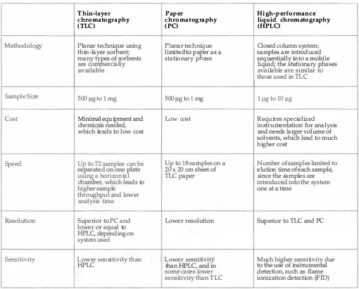
TLC is compared to other chromatographic techniques in
Table 1 . 1 and is discussed here; additional details can be found in other
sources ( Fried and Sherma 1 9 8 6a ) .
An Overview of Thin-Layer Chromatography 7
Thin-layer
Paper
High-performance
chromatography
chromatography
liquid chromatography
(TLC)
(PC)
(HPLC)
Methodology Planar t
echni
�
e using Planar technique Closed column
system;thin-layer sor ent; limited to pa
K
er as a samples are introduced many types of sorbents stationary p ase sequentially into a mobileare commercially liquid; the stationary phases
available available are similar to
those used in TLC
Sample Size 500 /lg to
1
mg 500 /lg to 1 mg1
/lg to 10 /lgCost
Minimal
equipment and Low cost Requires specializedchemicals needed, instrumentation for analysis
which leads to low cost and needs larger volume of
solvents, whiCh lead to much higher cost
Speed
Up
to72
samples can beU
t
to18
samples on a Numb
er of sampleslimited
to separated on onef
late 2x
20 em sheet of elution time of each sample,using a horizonta TLC paper since the samples are
chamber, which leads to introduced into the system
higher sample one at a time
throughput and lower analysis time
Resolution Superior to PC and Lower resolution Superior to TLC and PC
lower or equal to HPLC, depending on
system used
Sensitivity Lower sensitivity than Lower sensitivity Much higher sensitivity due
HPLC than HPLC, and
m
to the use of instrumentalsome cases lower detection, such as flame sensitivity than TLC ionization detection (FID)
Table 1.1.
A comparison of thin-layer chromatography, paper chromatography, and high-performance liquid chromatography.
8 Striegel . Hill
The main advantages of TLC are its low cost and the relative
speed of analysis. The materials needed to perform TLC are minimal.
They include a development chamber, chromatographic plates, solvents,
detection reagents, and reference materials. Also, TLC can be applied to
the detection and identification of a wide range of materials, like those
found in binding media.
Disadvantages of TLC analysis include the need for a larger
sample size and its lower sensitivity in comparison with other methods,
such as HPLC or GC. For binding media analysis by TLC, the sample size
is usually 500 fLg. For paint samples that contain a low binder concen
tration, samples up to 1 mg in size may be needed.
The History of
Tle
The development of modern thin-layer chromatography has its begin
nings in liquid chromatography. Like most scientific methods, chroma
tography evolved from initial phenomenological observations,
through early empirical research and the study of the underlying theo
retical principles, and finally, advancements in technique. While the
Russian botanist Tswett is generally credited with the discovery of chro
matography for his work in the separation of plant extracts on a column
of sorbent, others observed the phenomenon of separation before Tswett.
For example, in 1 844 C. Matteucci observed the rings left by a drop of
chocolate on a piece of paper. In 1 8 50 the German dye chemist
F. F.
Runge recognized the possibility of separating inorganic ions when
he observed their migration through paper. He initially described the
forces responsible for the separation as the "living forces," but later
attributed the phenomenon to capillary forces ( D ' Ascenzo and Nicolini
1 990 ) . Tswett's contribution to chromatography was the understanding
of adsorption, which led to chemical separation by liquid column
chromatography.
Although chromatographic techniques were little used for the
next thirty years, in the 1 93 0 s they were reintroduced by biochemists. In
1 94 1 , A. J . P. Martin and R. L . M. Synge introduced partition chroma
tography. They found that they could separate amino acids successfully if
a water phase was held stationary by adsorbing it on silica gel, while
permitting a mobile chloroform phase to flow over it. Thus they
described the use of a liquid stationary phase with a liquid mobile phase
and suggested that a gas might also be used as the mobile phase. In 1 952,
Martin and Synge were awarded a Nobel Prize in chemistry for their
theoretical development of partition chromatography ( Brooks 1 9 8 7 ) .
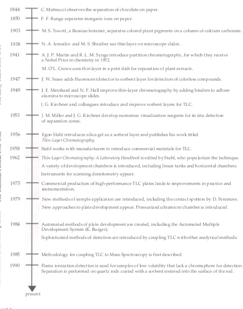
1844
An Overview of Thin-layer Chromatography
C Matteucci observes the separation of chocolate on paper. F. F. Runge separates inorganic ions on paper.
present
M. S. Tswett, a Russian botanist, separates colored plant pigments on a column of calcium carbonate.
N. A. Izmailov and M. S. Shraiber use thin layer on microscope slides.
A.
J.
P. Martin and R. L. M. Synge introduce partition chromatography, for which they receive a Nobel Prize in chemistry in1952.
M. O'L. Crowe uses thin layer in a petri dish for separation of plant extracts.
J.
W.
Sease adds fluorescent detector to sorbent layer for detection of colorless compounds.J.
E. Meinhard and N. F. Hall improve thin-layer chromatography by adding binders to adhere alumina to microscope slides.J.
G. Kirchner and colleagues introduce and improve sorbent layers for TLCJ.
M. Miller andJ.
C.
Kirchner develop numerous visualization reagents for in situ detection of separation zones.Egon Stahl introduces silica gel as a sorbent layer and publishes his work titled
Thin-Layer Chromatography.
Stahl works with manufacturers to introduce commercial materials for TLC
Thin-Layer Chromatography: A Laboratory Handbook
is edited by Stahl, who popularizes the technique. A variety of development chambers is introduced, including linear tanks and horizontal chambers. Instruments for scanning densitometry appear.Commercial production of high-performance TLC plates leads to improvements in practice and instrumentation.
New methods of sample application are introduced, including the contact spotters by D. Fenimore. New approaches to plate development appear. Pressurized ultramicro chamber is introduced.
Automated methods of plate development are created, including the Automated Multiple Development System (K. Burger).
Sophisticated methods of detection are introduced by coupling TLC with other analytical methods.
Methodology for coupling TLC to Mass Spectroscopy is first described.
Flame ionization detection is used for samples of low volatility that lack a chromaphore for detection. Separation is performed on quartz rods coated with a sorbent sintered into the surface of the rod.
A time line for the history of thin-layer chromatography.
1 0 Striegel . Hill
The Early Years: 1938-1951
The first reported use of a thin layer was in 1 93 8 by two Russian
workers, N. A. Izmailov and M. S. Shraiber. They separated plant
extracts on a slurried adsorption medium spread to a 2-mm-thick layer
by spotting an alcoholic plant extract in the center of the layer and
observing rings as the solution spread. Adsorption media that they tried
included chalk, talc, magnesium oxide, lime, and aluminum oxide. This
method is now called circular chromatography. They found that the
results obtained by this method were qualitatively the same as those
obtained by the usual chromatographic adsorption method of analysis.
This work was later reviewed in 1 94 1 by M. O'L. Crowe, who reported
that he and his colleagues had been using a thin layer of adsorbent in a
petri dish and achieving similar results ( Stahl 1 969a ) .
The fledgling technique was then improved b y the addition of
binders to the sorbents. This was first reported in
Analytical Chemistry
by J. E. Meinhard and N.
F.
Hall in 1 949. They used a binder to adhere
alumina to microscope slides, and separated inorganic ions by drop chro
matography. At about the same time, J. G. Kirchner and his colleagues at
the U.S. Department of Agriculture were working to determine the chem
istry of orange and grapefruit flavors. They initially attempted to
separate the chemicals that produced flavor by using paper chromatog
raphy. They also experimented with impregnating the paper with silicic
acid. Kirchner had a habit of clipping interesting abstracts out of
Chemical Abstracts.
One day, when one of Kirchner's colleagues was
quite frustrated about a difficult separation, Kirchner reached across his
desk, picked up the abstract of Meinhard and Hall's work, and said, "Try
this" (Kirchner 1 979) . After experimenting with the findings in the
abstract, Kirchner and his colleagues found that silicic acid bound with
amioca starch gave a satisfactory layer for TLC. He continued his work
with sorbent layers on glass plates and developed TLC essentially as we
know it today ( Fried and Sherma 1 9 8 6 b ) . Kirchner also observed that in
order to obtain reproducible results, conditions had to be standardized.
For instance, he showed that silicic acid must be screened to remove
coarse particles, and that it is necessary to run standards to verify that
the layers are properly prepared. Standards also serve as references when
comparing Rfvalues (see page 1 4 ) .
Another early improvement to the technique was the
methodology developed to assess the chromatogram. Colored separated
zones are visible, but many substances are colorless. To cope with this
problem, research on the detection of chromatographic zones progressed
in two main directions: physical methods and chemical methods.
An Overview of Thin-Layer Chromatography 1 1
The Classical Period: 1956-1980
Perhaps more than any other scientist, Egon Stahl advanced the tech
nique of thin-layer chromatography. Stahl was born in 1 924 in Germany.
He was the author of more than 1 50 scientific papers on the components
of medicinal plants, chromatography, and related scientific methods.
After World War II, Stahl analyzed drugs, tinctures, and medicinal plant
extracts for a pharmaceutical company. This work led him to the use of
paper chromatography. Later, he realized that layers with very small
pores and fine grains were needed to separate some chemical compounds.
First, he tried using cigarette paper, and later experimented with
magnesium grooves and rods and aluminum oxides. He succeeded in his
separations when he spread fine-grained aluminum oxides and silica gel
onto glass plates. While he knew that this new form of chromatography
was very similar to column chromatography, he slowly came to under
stand additional influences, such as the thickness of the layer, the length
of the run, chamber saturation, and other conditions. In 1 95 6 , he
published a first work with the title "Thin-Layer Chromatography" in a
professional magazine called
Die Pharmazie.
Thus, the technique was
named, but it did not immediately find wide acceptance.
Stahl lists the following reasons for this lack of acceptance:
I asked myself why it did not find acceptance and thought the
following reasons responsible: absence of commercially
available standard adsorbents of narrow range of grain size
for thin-layer chromatography; absence of suitable equipment
for preparing thin layers; and absence of suitable examples
stimulating the use of the method ( Stahl 1 979) .
H e kept these points i n mind a s h e continued his research. I n 1 95 8 , a
basic kit for TLC was manufactured by DESAGA, and "silica gel plates
according to Stahl for TLC" were manufactured by E. Merck. At this
point, the method became more popular, and by 1 962 so many papers
had been published that Stahl edited the first laboratory handbook on
TLC,
Dunnschlicht-Chromatographie, ein Laboratoriumshandbuch .
A
second edition, which was translated into English in 1 967, contained
more than one thousand pages ( Stahl 1 969b ) . A major breakthrough in
the field came in the early 1960s when convenient precoated plates
became commercially a vaila ble.
12 Striegel . Hill
Instruments for scanning densitometry using absorbance or
fluorescence measurements in the reflectance or transmission mode first
appeared in the mid- 1 960s. This was initially reported by M. S. J. Dallas
et al. ( Dallas et al. 1964) and K. Genest ( Genest 1 96 5 ) . Since that time,
densitometry has undergone continuous changes, especially with the
introduction of new technology such as solid-state video cameras and
image processing ( Belchamber and Brinkworth 1 98 8 ) .
I n the mid - 1 970s, the commercial production o f high-perfor
mance TLC ( HPTLC) plates provided the impetus for improvements in
practice and instrumentation. These high-performance TLC plates differ
from conventional TLC plates in a number of ways, but mainly in the size
of the particles used in the manufacture of the plates and the need for a
much more precise and instrumentalized approach in order to obtain
the best results ( Dallas et al. 1 98 8 ) . This development led to methods
termed "high-performance TLC," by A. Zlatkis and R. E. Kaiser ( 1 977) .
The Modern Period: 1981-Present
After a decline in the reported use of TLC in the 1 970s, there was
renewed interest in the technique. (The decline corresponded to the
period of development of the HPTLC method. ) The "renaissance" of the
TLC technique may have been related to improved methodology, with an
emphasis on the instrumentation and automation of operations. Other
developments have included new approaches in TLC plate development
and the coupling of TLC with spectrometric methods.
Automation of operations in TLC has focused on the
particular steps with the greatest potential for error. These included
application of sample solutions, chromatographic development,
detection, and quantitative in situ evaluation. In order to use the power
of HPTLC plates, new methods of sample application were introduced,
including the contact spotter by D. Fenimore ( Fenimore and Meyer 1 979)
and the Automatic TLC sampler ( CAMAG, Switzerland). One automated
method derived by K. Burger ( 1 984 ) , the Automated Multiple Devel
opment system (AM D ) , resulted in a dramatic improvement of chromato
graphic selectivity. This apparatus can be used for one to twenty-five
individual developments. The procedure involves very small developing
distances, with each development being longer than the previous one by
3-5 mm. Between each development, the solvent system is completely
removed and the plate is dried under vacuum. The solvent system can be
changed with each development. Improvements in the instrumentation of
scanning densitometers were also seen during this era.
New approaches in the development of the TLC plate have
focused on the transport of the mobile phase through the stationary
phase. Conventional TLC relies on the rise of the mobile phase by
capillary action, which can take up to several hours depending on the
TLC system. AMD is also based on capillary action for the transport of
the mobile phase. Several new techniques based on an alternative
An Overview of Thin-Layer Chromatography 1 3
systems are a n example o f a controlled mobile phase i n a n open system
and have been used in the development of TLC plates. The sample to be
separated is spotted in the middle of the plate. The solvent system is
supplied at the center of the spot, and the mobile phase then moves
outward by centrifugal forces as the plate is spun. Pressure can also be
used to alter the transport of the mobile phase, similar to HPLC methods
(Ferenczi-Fodor et al. 1 991 ) . The first step in the development of a planar
version of HPLC came with the development of a pressurized ultra micro
chamber, the basic instrument for overpressured layer chromatography
( OPLC) (Tyihak et al. 1 979) . In OPLC, a pump system is used for the
admission of the solvent system .
Sophisticated methods o f detection have been introduced by
coupling TLC with spectroscopic methods, such as infrared spectroscopy
(TLC/FTIR) or mass spectroscopy (TLC/MS) (Jork 1 993 ) . As early as
1 964, it became feasible to record the reflectance spectra of the sepa
ration zones in the ultraviolet and visible ranges of the spectra. This
methodology was extended to the infrared spectra by coupling TLC to
Fourier transform infrared spectroscopy. A diffuse reflectance infrared
spectroscopy unit has been specifically designed for this purpose
( Bruker Instruments, Karlsruhe, Germany), and targeted quantitative
determinations can be made at a wavelength that is specific for a
particular compound. Methodology for the coupling of TLC to mass
spectroscopy was first described in 1985 ( Chang and Andrawes 1 9 8 5 ) . In
this technique the zone is removed from the TLC plate and transferred to
the mass spectrometer. Continued research in this area brought about
interface systems for on-line coupling of TLC to mass spectroscopy.
Theoretical Aspects of Thin-Layer Chromatography
Descriptions of the general theory of thin-layer chromatography can be
found in the literature ( Kowalska 1 991 ; Poole and Poole 1 991 ; Fried and
Sherma 1986a; Brenner et al. 1 96 5 ) . Presented here is a summary of
important theoretical aspects that are valuable to an understanding of
chromatographic separation by TLC.
The main purpose of TLC is to separate or resolve compo
nents of mixtures. As applied to the analysis of binding media, the sample
is a mixture of chemical building blocks or compounds. The chro
matogram of the sample can be characterized by the number and location
of spots or zones. By comparing sample chromatograms to chromato
grams of known reference materials, the sample may be identified .
1 4
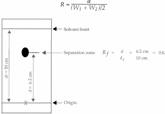
Figure
1.3.
Calculation of the
R,
value in TLC.Striegel . Hill
in the direction of the flow of the mobile phase, and the resistive forces
impede this movement by pulling components out of the flow of the
mobile phase and holding them on the stationary phase by adsorption.
Thus, each molecule follows a "stop-and-go" path through the sorbent
layer. At the end of development, each component spot has traveled a
certain distance. Components that are more strongly attracted to the
sorbent layer will travel a shorter distance, while components that are
more soluble in the mobile phase will travel a longer distance from the
origin. The spots become larger in size due to fluctuations in the
movement of the individual molecules ( Fried and Sherma 1986c).
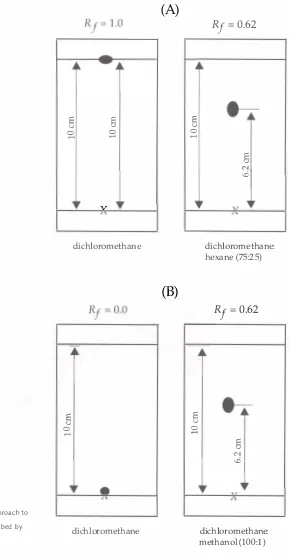
The migration of the components in a chromatogram can be
characterized by a basic parameter called the
Rf
value.It is calculated
as the ratio of the distance moved by the solute (component) , to the
distance moved by the mobile phase front ( Sherma 1 99 1 ) . This can be
expressed as:
distance moved the solute
Rf=
distance moved by the mobile phase front
The distance moved by the solute is measured from the origin to the
center of the zone. An illustration of the calculation of an
Rf
value is
shown in Figure 1 .3 . Identification of compounds by TLC is based
on the comparison of chromatograms of known and unknown materials.
Rf
values facilitate this comparison and are used as guides to the relative
migration and sequencing of components within a mixture. It should
be noted that there are many factors that can cause variance in the
Rf
values of a chromatogram, therefore known materials must be run next
to unknown samples on the same chromatographic plate for comparison.
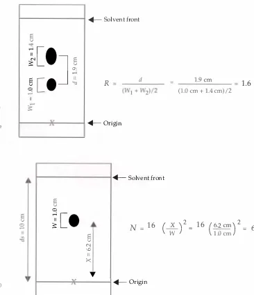
A measure of the selectivity of a TLC system is the
resolutionof two chromatographic zones. The resolution
(R)
is defined as the
distance between two zone centers
(d)
divided by the average widths
(W)
Figure
1.4.
Calculation of the chromatographic resolution
determined from two spots on a plate. The
resolution is the ratio of the separation of zone
centers to the average zone width.
Figure
1.5.
Calculation of the theoretical plate number
(N)
in TLC.An Overview of Thin-Layer Chromatography
An example of this calculation can be seen in Figure 1 .4. The resolu
tion of the system can be improved by moving the zones farther
apart ( increasing the selectivity) . The resolution can also be improved
by decreasing the widths of the zones by improving the efficiency
of the system .
The efficiency of a TLC system i s measured b y a parameter
called the
theoretical plate number(N). This value is useful for
comparing chromatographic methods as well as the efficiency of indi
vidual TLC systems. It is calculated from the equation:
References
Belchamber, R. M., and S. J . Bri n kworth
1 9 8 8 . Qualitative and Quantitative Image Analysis of Fluorescence from High Performance Thin-Layer Chromatography. In Recent Advances in Thin-Layer Chromatography, ed.
F.
A. A. Dallas, H. Read, R. J. Ruane, and1.
D. Wilson, 3 7-43 . London: Pknum.Brenner, M., and A. N i ederwieser
1 9 6 1 . Durchlaufende Dunnschicht-chromatographie. Experimentia 1 7 ( 5 ) :237-3 8 .
Brenner, M . , A. N i ederwieser, G . Pataki , and R. Webber
1 9 6 5 . Theoretical Aspects of Thin-Layer Chromatography. In Thin-Layer Chromatography: A Laboratory Handbook, ed. Egon Stahl, 75-1 3 3 . Berlin: Springer-Verlag.
Brooks, Ken neth C.
1 9 8 7. Chromatography. Encyclopedia of Physical Science and Technology 2 : 760-70.
Bu rger, K.
1 9 84. TLC-PMD Thin-Layer Chromatography with Gradient Elution in Comparison to HPLe. Fresius
Z.
Anal. Chem. 3 1 8 (3-4 ) :228-3 3 .Chang, T. T., a n d
F.
Andrawes1 9 8 5 . In Proceedings of the 3rd International Symposium for Instrumental HPTLC in Bad Durkheim, ed. R. E. Kaiser, 427-3:). IFe.
Dal las, F. A. A., H . Read, R. J. Ruane, and I . D. Wilson, eds.
1 9 8 8 . Recent Advances in Thin-Layer Chromatography. London: Plenum.
Dallas, M. S. J . , C. B. Barrett, and
F.
P. Padl ey1 9 64. Joyce Loeb! Publication. Vol . 3 .
D'Ascenzo, G i useppe, a n d N icoletta N icol i n i
An Overview of Thin-Layer Chromatography 1 7
Fen imore, D . , and C . Meyer
1 979. Contact Spotting-A New Approach to Sample Application in Thin Layer Chromatography. Journal of Chromatography 1 8 6 (Dec } : 5 5 6-6 1 .
Ferenczi-Fodor, Katalin, Emil Mincsovi cs, and Erno Tyihak
1 9 9 1 . Overpressured Layer Chromatography. I n Handbook of Thin-Layer Chromatography, ed. Joseph Sherma and Bernard Fried. Vol . 5 5 , 1 55-79 . New York: Marcel Dekker, Inc.
Fried, Bernard, and J oseph S herma
1 9 86a. Thin-Layer Chromatography: Techniques and Applications. 2d ed., Vol. 3 5 . Chromatographic Science Series, ed. Jack Cazes. New York: Marcel Dekker, Inc.
1 9 86b. Introduction and History. Chapter 1 in Thin-Layer.
1 9 86c. Mechanism and Theory. Chapter 2 in Thin-Layer.
Genest, K.
1 96 5 . A Direct Densitometric Method on Thin-Layer Plates for Determination of Lysergic Acid Amide and Clavine Alkaloids in Morning Glory Seeds. Journal of Chromatography 1 8 :53 1 .
Grinberg, Nelu
1 990. Introduction to Modern Thin-Layer Chromatography, ed. Nelu Grinberg, 1 -4 . New York: Marcel Dekker, Inc.
J ork, H .
1 9 93. Advances i n Thin-Layer Chromatography: Part 2 . American Laboratory 25 (June}:24B-24F.
Ki rch ner, J ustus G.
1 9 79. Justus G. Kirchner. In
75
Years of Chromatography-A Historical Dialogue, ed. L. S. Ettre and A. Zlatkis. Vol. 1 7, 2 0 1 -8 . Amsterdam:Elsevier Scientific Publishing.
Kowalska, Teresa
1 9 9 1 . Theory and Mechanism of Thin-Layer Chromatography. In Handbook of Thin-Layer Chromatography, ed. Joseph Sherma and Bernard Fried. Vol . 55, 43-69. New York: Marcel Dekker, Inc.
Mein hard , J. E., and N. F. Hall
1 949. Surface Chromatography. Analytical Chemistry 2 1 : 1 8 5 .
Miller, J o h n M., a n d J _G . Kirchner
1 8 Striegel . Hill
Poole, Col i n F., and Salwa K. Poole
1 9 9 1 . Chromatography Today. Amsterdam: Elsevier Scientific Publishing.
Sease, J. W.
1 947. The Use of Fluorescence Absorbents and the Chromatography of Colorless Compounds. Journal of the A merican Chemical Society 69 ( 9 ) :2242-44.
Sherma, J oseph
1 9 9 1 . Basic Techniques, Materials and Apparatus. In Handbook of Thin-Layer Chromatography, ed. Joseph Sherma and Bernard Fried. Vol . 55, 3-4 1 . New York: Marcel Dekker, Inc.
Stahl, Egon
1 9 69a. History of the Development of Thin-Layer Chromatography. Chapter A in
Thin-Layer Chromatography: A Laboratory Handbook, ed. E. Stahl, 1 -4. Berlin:
Springer-Verlag.
1 979. 75 Years of Chromatography-A Historical Dialogue, ed. L. S. Ettre and A. Zlatkis. Vol. 1 7, 425-3 5 . Amsterdam: Elsevier Scientific Publishing.
Stah l , Egon, ed.
1 969b. Thin-Layer Chromatography: A Laboratory Handbook. 2d ed. Berlin: Springer-Verlag.
Tyi hak, E., E. Mincsovics, and H. Kalasz
1 979. New Planar Liquid-Chromatographic Technique-Overpressured Thin-Layer Chromatography. Journal of Chromatography 1 74 ( 1 ) : 75-8 1 .
Ziatkis, A., and R. E . Kaiser, eds.
Chapter
2
Technique of Thin-Layer Chromatography
The purpose of this chapter is to present:
•
An introduction to the technique of thin-layer chromatog
raphy
•
A brief description of the steps involved in performing a
chroma togra phic separation
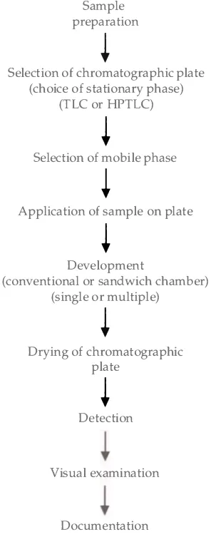
The process of thin-layer chromatography involves the series of steps
shown in Figure 2 . 1 . These steps include sample preparation, selection of
the chromatographic plate, selection of the mobile phase, application
of the sample to the plate, development of the plate, drying of the plate,
detection of the separation zones, visual examination, and documentation.
Sam ple Preparation
The first step is the preparation of the sample, which varies depending on
the type of material being analyzed. For binding media analysis, two
principal methods of sample preparation are used: dissolution of the
sample in an appropriate solvent ( for waxes or resins ) or acid hydrolysis
of the sample into its components ( for proteins and carbohydrates ) . The
choice of the solvent is dependent on the solubility of the sample. The
properties of the carrier solvent are also important since it is the vehicle
used to apply the sample to the plate.
For waxes and resins, the sample is dissolved in a carrier
solvent, then applied to the plate. A good solvent for the dissolution of
the sample is one that readily dissolves all of the components of interest.
Tables of solubility are listed for film substances in various organic
solvents ( Gettens and Stout 1 96 6 ) . From this information, chloroform
was chosen for the dissolution of waxes, and ethyl acetate was chosen for
the dissolution of resins.
20
Figure 2.1 .
The process of thin-layer chromatography.
Striegel . H i l l
Sample preparation
�
Selection of chromatographic plate (choice of stationary phase)
(TLC or HPTLC)
�
Selection of mobile phase
�
Application of sample on plate
�
Development
(conventional or sandwich chamber) (single or multiple)
�
Drying of chromatographic plate
�
Detection
Visual examination
Documentation
glass vials with preweighed binding media samples are placed in the
Pierce reaction chamber_ After acid is added to the sample, a vacuum is
pulled through the Pierce Miniert valve to remove air that might cause
oxidation when the sample is heated. The reaction chamber is placed in a
preheated, 1 05 °C oven, and the samples are heated 5-24 hours,
depending on the concentration of the acid being used in this step. After
acid hydrolysis, each sample is dried under a stream of nitrogen, again to
prevent oxidation, which flows through a needle from the gas manifold
into the tube and over the sample_ Once dry, the samples are reconsti
tuted in a carrier solvent such as methanol.
The acid hydrolysis may be performed as described above
( carbohydrates ) or through vapor phase hydrolyzation (proteins ) , where
acid is added to the bottom of the reaction chamber, but not to the
sample vials.
Selection of the Ch romatographic Plate
Technique of Thin-Layer Chromatography 2 1
--
i
cgPERCE
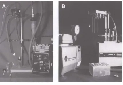
Figure 2.2.
Two types of hydrolysis equipment. On the left is a system composed of various laboratory supplies that can be used to perform vapor phase or conventional acid hydrolysis. A sample is weighed directly into 1 -ml vials (a). The vials are placed into a reaction chamber (b). Acid is added to the chamber or the samples; then the chamber is sealed with a cap containing a Miniert valve (c). The reaction chamber is flushed and placed under vacuum for three cycles. This can be done by inserting a needle (d) that is connected via tubing to a two-way valve (e). The valve can be directed to a vacuum pump (f) or a tank of nitrogen (not shown). On the right is a commercially available system manufactured by Pierce Corp. The Pierce Reacti-Therm sample incubation unit is used for conventional acid hydrolysis of proteins and carbohydrates. Components of this system i nclude: (g) vacuum pump, (h) aluminum heating block, (i) heating unit, (j) vacuum hydrolysis tubes, (k) needles, and
(I)
gas manifold.Resolution of the components of a sample depends on both the stationary
phase and the mobile phase chosen for the analysis. Silica gel, an
excellent stationary phase for many applications, is widely used in thin
layer chromatography. Prepared plates of silica gel are commercially
available from several manufacturers. It is important to note that vari
ances in the manufacture of a TLC plate can greatly affect the separation
of the components. To avoid problems of this sort, the plates are
purchased from the same manufacturer and prepared consistently for
better reproducibility. The plate is usually prewashed in methanol and
activated by heating.
22 Striegel . H i l l
One drawback can be the low volume of sample that must be loaded onto
the HPTLC plate for optimum performance, as large amounts of sample
on the plate result in a poorer separation.
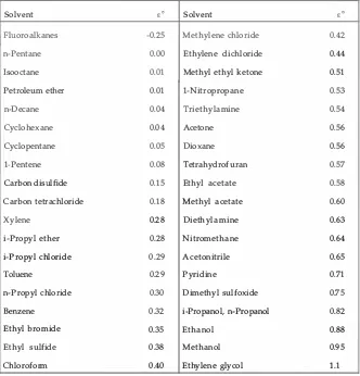
Selection of a Solvent System
A key step in designing a TLC application is the choice of the solvent
system, or mobile phase (see also Chapter 3, pages 2 8 -3 1 ) . While there
are several theories on the optimization of solvent systems ( D eSpiegeleer
1 9 9 1 ) , the selection of solvents for this work was based on testing
systems noted in the literature ( Bruno et al. 1 9 8 9; Stahl 1 96 9 ) .
Spotting t h e Sample
The fourth step in the process is the spotting of the sample solution
to the prepared TLC plate. The sample solution is drawn into a glass
capillary tube micropipette. A volume of 0 . 1 to 1 . 0 fll of the sample
solution is spotted on the baseline of the plate. A template or ruler is
often used as a guide so that the spots are equally spaced along the
baseline. The application of the spot is an important step often requiring
practice to obtain optimally small, round sample spots. One method
for obtaining small spots on the origin involves applying portions of the
total volume and drying the spot with an air gun ( cool setting) between
each application.
Development of the TLC Plate
After the sample spots dry, the plate is placed in a development chamber
that contains a solvent or mixture of solvents ( for a detailed description
of different types of chambers, see Chapter 3, pages 3 1-34 ) . There are
two types of chambers used in the analysis of binding media: the conven
tional chamber and the sandwich chamber. The conventional chamber is
easiest to use, although it must be presaturated with solvent vapors. The
process usually takes 1 5-3 0 minutes. This type of chamber requires
approximately 30 ml of solvent system.
Technique of Thin-Layer Chromatography 23
the evaporation of the volatile solvents and to keep the vapor space satu
rated, the entire sandwich chamber is placed inside a tightly sealed vessel.
The plate is developed for a specified distance, usually 8 cm
for the 1 0-cm HPTLC plates in a sandwich chamber, and 1 7 cm for the
20-cm TLC plates in a conventional chamber. Then the plates are
removed from the chamber and allowed to dry at room temperature in
the fume hood. This drying process is dependent on the solvent system
used, but usually takes about 30 minutes.
Detection of Separation Zones
The chemical components of the sample are separated on the TLC plate.
They may be colored or colorless compounds. If they are colorless they
must be made visible in some manner. The detection of the individual
components is aided by reacting the components with a chemical reagent
to form visible spots under normal or ultraviolet light ( additional infor
mation on physical and chemical methods of detection is presented in
Chapter 8, pages 67-73). The detection reagent can be applied by dipping or
spraying. Spraying is the most commonly used method, since it requires
minimal amounts of the reagent. Reusable spray bottles dispense an ultra
fine mist that is ideal for the visualization of components on a TLC plate.
Visual Exami nation
After detection, the plate is examined to determine the location of the
components. The plate is first viewed under normal light. Any discol
oration that may indicate separation zones is marked lightly with pencil.
Next, the plate is examined under ultraviolet light. Two types of UV light
are used, a range of short-wavelength UV light (centered at 254 nm) and
a range of long-wavelength UV light (centered at 366 nm) . Any fluores
cence is again marked with a pencil.
Docu mentation
The chromatogram is carefully documented. The documentation includes
a record of the materials analyzed, the type of plate used, the solvent
system used, the type of chamber, and other conditions. In addition, a
photocopy ( for the lab notebook) and photographs ( for permanent docu
mentation ) of the TLC plate are made. The plate is photographed on
both black-and-white print and color slide film. Figure 8 . 6 (page 75 )
shows a simple chamber used to photograph TLC plates under ultraviolet
light. It is constructed of a cardboard box, with panels inserted to
support UV lamps at 45° angles to the plate (a description of techniques
for documentation is given in Chapter 8, pages 73-75 ) .
References
Bru no, T., J . Paris, and D. N . Svoronos
1 9 89. Thin Layer Chromatography. In CRC Handbook of Basic Tables for Chemical Analysis, 1 2 8-5 9. Boca Raton, FL: CRC Press, Inc.
DeSpiegeleer, B. M. J .
1 9 9 1 . Optimization. In Handbook of Chromatography, ed. Joseph Sherma and Bernard Fried. Vol . 55, 71-85. New York : Marcel Dekker, Inc.
Gettens, Rutherford J . , and George Stout
1 9 6 6 . Paintings Materials: A Short Encyclopedia. 2d ed. New York:
Dover Publications, Inc.
Stah l , Egon , ed.
1 969. Thin-Layer Chromatography: A Laboratory Handbook. 2d ed. Berlin:
Chapter
3
Methodology for Thin-Layer Chromatography
This chapter provides detailed information needed to develop TLC
systems for use on samples, in general, and binding media, adhesives,
and coatings, in particular. Sections within this chapter present:
•
A report on the types of sorbent layers available and their
interactions with both the solute and the solvent system
•
A discussion of solvent systems
•
A detailed description of development chambers and tech
niques of development
•
An introduction to detection methods
•
A prelude to documentation needed for TLC analyses
Conventional thin-layer chromatography requires minimal
equipment and supplies, including pipettes for sample application, a plate
coated with a thin layer of sorbent, the appropriate solvent system and a
development chamber for the application, a means of detecting the
resulting chromatogram, and equipment to document the chromatogram.
The equipment can be simple, such as a screw-top jar for a developing
chamber, or complex, such as a scanning densitometer for the quanti
tative analysis of a chromatogram. This chapter presents the basic
equipment needed for the analysis of the organic binders, adhesives,
and coatings found on artifacts. It also details some of the underlying
theories for the choice of equipment and the development of new TLC
systems. In addition, brief descriptions of more sophisticated methods
will be given.
2 6 Striegel . H i l l
chosen. After the plate is developed, the chromatogram is assessed. This
requires visualization of the individual components of the sample that are
separated on the plate, usually by chemically reacting the components
with a detection reagent.
There are four mechanisms of separation that may occur
during TLC: adsorption, liquid-liquid partition, ion exchange, or steric
exclusion ( Gocan 1 99 0 ) . The two main mechanisms-adsorption and
partition-will be discussed here.
Adsorption
is the process by which the solvent and the sample
compete for reactive sites on the stationary phase ( usually a polar
sorbent) . Components of the solute will compete more effectively or less
effectively than the solvent, depending on the polarity of both the
component and the solvent. For example, the most commonly used
sorbent is silica gel. On the surface of a silica gel layer is a network of
polar -OH groups bound to an Si02 skeleton. Adsorption on silica gel
involves hydrogen bonding between functional groups on the sample and
the -OH groups of the silica gel. Some molecules bond better to the -OH
groups than others, and will travel a shorter distance from the origin.
Those that bond more weakly to the -OH groups of the silica gel will
travel a farther distance from the origin.
Liquid-liquid partition
is the process that involves a liquid
stationary phase bound to a solid sorbent. The components of the sample
will spend a portion of the migration time in the liquid stationary phase
and a portion of the time in the liquid mobile phase. Separation occurs
when the components reside in both phases and have different retentions.
The liquid-liquid partition mechanism can also take place on silica gel,
under slightly different conditions, depending on how the plate is
prepared ( i . e . , activated or not activate d ) . Water binds to silica either as
"capillary" water or as water associated with the -OH groups of the
surface. This water can act as a stationary phase bonded to the sorbent.
When the stationary phase is polar and the mobile phase is
less polar or nonpolar, the system is called
normal phase TLC.If the
sorbent is chemically altered ( e . g . , by bonding nonpolar groups to the
surface of the silica gel or by coating or impregnating the stationary
phase with a nonpolar organic solvent), a nonpolar stationary phase can
result ( Gasparic 1 99 2 ) . If this nonpolar stationary phase is used with a
polar mobile phase, the system is called a
reversed pha
se
(RP) system.One of the advantages of chemically bonded phases is the almost
unlimited variety of commercial or laboratory-prepared plates with a
wide range of polarities.
Sorbent Layers
Methodology for Thin-Layer Chromatography
quality of these plates could vary considerably. Quality TLC plates are
now commercially available with a variety of sorbent layers. This
section presents the components of the chromatographic plate, a
comparison of TLC and HPTLC plates, and details the use of sorbent
layers used in the analysis of organic materials from cultural obj ects.
27
The components of a TLC plate are the support, the sorbent
binder, the sorbent layer, and sometimes chemical additives that aid in
detection of the separation zones. The
supportof the thin layer is most
commonly a glass plate. Other materials used as a support include thin
plastic sheets and aluminum foil. The glass plate offers the advantage of
being the most inert backing material; it is also a rigid planar support.
The size of the plate is typically 20
X
20 cm. Other sizes include
5
X
20 cm, 10
X
20 cm, 10
X
10 cm, and "micro" ( microscope slides) .
Glass plates are available prescored, o r can b e scored with a diamond
point and broken into smaller sizes. Disadvantages of breaking the plates
include safety hazards and the possibility of producing j agged edges. An
advantage of plastic sheets is that they may be cut into various sizes with
scissors or a blade.
The sorbent layers can be bound or unbound to the glass
plate . In the early days of the technique, starches were used as
sorbent bindersin the preparation of TLC plates. Gradually, other binders that
gave better results were found. Today the most commonly used binder is
gypsum, designated with the letter G. For example, the Merck silica gel G
plate has a thin layer of silica gel bound with gypsum.
Sorbent layers can be made from many different materials.
The most common sorbent layer used in TLC is silica gel. Many of the
modern sorbent layers are based on the modification of silica layers. The
-OH functional groups can be replaced with different functional groups,
including long chain hydrocarbons. Hydrocarbon functional groups
usually make the surface more nonpolar; if this is the case, the sorbent
layers can be used for reversed phase chromatography and are designated
with the letters RP by the manufacturer. Silica gel layers can also be
modified with other functional groups to fine-tune the polarity of the
surface. One such sorbent used for polyamide plates is made by the
addition of amide groups to the silica gel surface. Another sorbent used
in TLC is cellulose. The cellulose fibers used in thin layers are shorter in
length than those found in chromatography paper. Sorbent layers can be
impregnated with buffers, chelating reagents, metal ions, or many other
chemicals to aid in the selectivity and resolution of compounds
( Sherma 1 99 1 ) .
A TLC plate may include
chemical additivesthat fluoresce
upon exposure to ultraviolet light; these additives are present to facilitate
the detection of colorless compounds. Fluorescent and phosphorescent
substances are excited into an unstable energy state by UV light, and
release part of the stored radiant energy when they return to a ground
state . This emitted radiation usually lies in the visible part of the
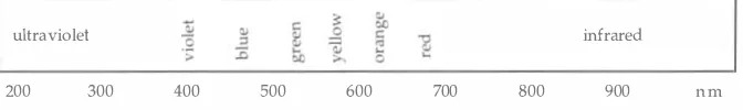
spectrum. An illustration of the radiation spectrum is shown in
wave-28
Figure 3.1 .
A schematic illustration of the radiation
spectrum, described in terms of wavelength.
Striegel . Hill
ultraviolet
infrared
200
300
400
500
600
700
800
900
nm
length of UV light. Separation zones appear as dark spots on the bright
background. Inorganic indicators that phosphoresce upon exposure to
short wavelength (centered at 254 nm) UV light include tin-activated
strontium compounds, uranyl acetate, magnesium-activated zinc silicate,
and zinc cadmium sulfide. Most fluorescent indicators are designated as
F254 or UV 254 on the label of the plates.
Conventional TLC and HPTLC plates can be obtained in a
variety of sorbent layers. The major differences between TLC and
HPTLC plates are the particle size and the particle distribution of the
sorbent, and the thickness of the layer. The most common HPTLC
sorbent is silica gel; other commercially available plates include cellulose
and polyamide. The particle size of silica gel used for HPTLC plates is
5 f..lm, while that used for conventional plates is 2 0 f..lm. The thickness of
a high-performance layer is 1 00-200 f..lm, compared to 250 f..lm found on
conventional plates. HP layers are more efficient because they produce
tighter zones, better resolution, and more sensitive detection.
It should be noted that plates with the same designation from
two different manufacturers do not necessarily exhibit the same chro
matographic behavior. Plates from different manufacturers may have
different layer characteristics even when the same sorbent and binder are
used. For example, a precoated silica gel plate from Manufacturer A
will not always result in a chromatogram which matches one found on a
silica gel plate from Manufacturer B. Once a good separation is obtained
on a particular plate, it is important to "standardize" the plate used
(Touchstone and Dobbins 1 9 8 3 a ) .
Two principal plates for the identification of binding media in
paint are considered in this publication. The hydrolysates of protein
samples are separated on Macherey-Nagel MN300 cellulose plates for
the identification of proteinaceous binders, and Merck HPTLC silica gel
F254 plates are used in the identification of waxes, resins, and sugars.
Solvent Systems