v
PERANCANGAN DAN REALISASI LENGAN ROBOT TIGA
DERAJAT KEBEBASAN MENGGUNAKAN SENSOR
AKSELEROMETER ADXL345
DAN ARDUINO
Maria Fransiska 0822040
Jurusan Teknik Elektro, Fakultas Teknik Universitas Kristen Maranatha
Jl. Prof. Drg. Suria Sumantri 65, Bandung 40164, Indonesia
ABSTRAK
Manipulator lengan robot umumnya terdiri dari motor servo yang berfungsi sebagai sendi dan gripper sebagai jari pada lengan manusia. Sensor pergerakan lengan robot yang dirancang berdasarkan hand gesture interface umumnya menggunakan sensor berupa akselerometer dan magnetometer.
Dalam tugas akhir ini dilakukan perancangan dan realisasi lengan robot tiga derajat kebebasan menggunakan sensor akselerometer ADXL345 dan Arduino. Akselerometer ADXL345, dibantu dengan sensor magnetometer HMC5883L yang keduanya bekerja sebagai sensor gerak orientasi, dipasang pada sarung tangan yang dipakai oleh pengguna dan informasi kedua sensor tersebut akan diolah melalui Arduino. Setelah diolah, informasi ini digunakan motor servo untuk bergerak mewakili gerakan base rotation, elbow flex, dan
wrist yaw. Sedangkan switch digunakan untuk menentukan kondisi gripper
membuka atau menutup.
Hasil realisasi lengan robot dengan tiga derajat kebebasan, memiliki keberhasilan yang terlihat dari lengan robot yang mengikuti lengan pengguna dengan simpangan yang terjadi pada elbow flex(x) yaitu berkisar antara 0º-9º, simpangan yang terjadi pada saat gerakan wrist yaw(y) yaitu berkisar antara 2º-15º dan simpangan yang terjadi pada saat gerakan base
rotation(z) yaitu berkisar antara 0º-20º. Pencapitan dan pemindahan barang
berdasarkan posisi awal dan posisi akhir gerakan base rotation lengan pengguna yang terbaca oleh sensor dibandingkan posisi akhir lengan robot memiliki simpangan berkisar antara 0º-20º. Jangkauan maksimal pada gerakan
elbow flex untuk pencapitan barang adalah yang memiliki ketinggian minimal
17 cm dengan kemiringan terhadap permukaan lengan robot tidak kurang dari 30º dan tidak lebih dari 150º.
Kata kunci : ADXL345, akselerometer, Arduino, base rotation, command line interface, elbow flex, gesture, gripper, human interface, HMC5883L, lengan
THE DESIGNING AND REALIZATION THREE DEGREES OF
FREEDOM ROBOT ARM USING ACCELEROMETER
ADXL345 AND ARDUINO
Maria Fransiska 0822040
Jurusan Teknik Elektro, Fakultas Teknik Universitas Kristen Maranatha
Jl. Prof. Drg. Suria Sumantri 65, Bandung 40164, Indonesia
ABSTRACT
Robot arm manipulator usually consists of servo motors and grippers. Movement’s sensors of robot arm are designed based on human interface, like hand gesture’s interface that commonly use accelerometer and magnetometer.
On this final assignment, the writer has done the design and realization by applying accelerometer ADXL345 and arduino for three degrees robot arm. ADXL345 is assisted by magnetometer HMC5883L, both of them work as orientation sensor that sensing rotation movement and their information are received and also processed by Arduino. After their information is proceeded, it used to actuate the servo on base rotation, elbow
flex, dan wrist yaw. Meanwhile, the switch is used to manage the gripper
whether it is open or close.
The realization of robot arm with three degrees of freedom has succeed as the robot arm follow user arm with deviation at elbow flex(x) is around 0º-9º, deviation at wrist yaw(y) is around 2º-15º and deviation at base
rotation(z) is around 0º-20º. Pick and place of the goods is based on user
arm’s base rotation at first position to end position has around 0º-20º deviation. Maximum range of elbow flex movement for picking goods is for goods that has 17 cm height with tilt from base that not less from 30º and not more than 150º
Keywords : ADXL345, accelerometer, Arduino, base rotation, command line
vii
DAFTAR ISI
Halaman
HALAMAN JUDUL ... i
LEMBAR PENGESAHAN LAPORAN TUGAS AKHIR ... ii
PERNYATAAN ORISINALITAS LAPORAN TUGAS AKHIR ... iii
PERNYATAAN PUBLIKASI LAPORAN TUGAS AKHIR ... iv
KATA PENGANTAR ... v
1.8 Sistematika Penulisan... 4
BAB II LANDASAN TEORI 2.1 Robotika ... 5
2.1.1 Komponen Dasar Sebuah Robot... 5
2.1.2 Geometri Robot ... 8
2.2 Arduino ... 9
2.2.1 Software - Arduino Development Environment ... 11
2.2.2 Hardware - Arduino Board ... 12
2.3 Akselerometer ADXL345 ... 12
2.4 Magnetometer HMC5883L ... 15
2.5 Motor Servo ... 16
2.6 Tactile Push-Button ... 18
BAB III PERANCANGAN DAN REALISASI 3.1 Diagram Blok Perancangan... 19
3.2 Perancangan Hardware ... 20
3.2.1 Perancangan Mekanik... 20
3.2.2 Perancangan Elektronika ... 24
3.3 Perancangan Software ... 26
3.3.1 Pengujian Akselerometer dan Magnetometer... 26
3.3.2 Flowchart... 28
3.3.3 Kode Program ... 31
BAB IV PENGUJIAN LENGAN ROBOT 4.1 Pengamatan Gerakan Lengan Robot ... 37
4.2 Data Pengamatan ... 40
4.2 Analisis Data ... 43
BAB V KESIMPULAN DAN SARAN 5.1 Kesimpulan ... 44
5.2 Saran ... 44
DAFTAR PUSTAKA
ix
DAFTAR TABEL
Halaman
1. Tabel 2.1 Toolbar Button pada Software Arduino ... 11
2. Tabel 2.2 Ilustrasi Cara Kerja Akselerometer ... 13
3. Tabel 3.1 Perancangan Gerakan Lengan Robot ... 23
4. Tabel 4.1 Pergeseran Lengan Robot terhadap Lengan Pengguna ... 40
DAFTAR GAMBAR
Halaman
1. Gambar 2.1 Robot Lengan dengan 6 Derajat Kebebasan ... 8
2. Gambar 2.2 Open Loop Control... 8
9. Gambar 2.9 Akselerometer ADXL345 ... 14
10. Gambar 2.10 Magnetometer HMC5883L ... 15
11. Gambar 2.11 Ilustrasi Penghitungan Heading Kompas ... 15
12. Gambar 2.12 Komponen Dalam Motor Servo ... 16
13. Gambar 2.13 Bentuk Motor Servo dan Konfigurasi Kabel ... 16
14. Gambar 2.14 Tactile Push-Button ... 18
15. Gambar 2.15 Karakteristik Tactile Push Button ... 18
16. Gambar 3.1 Diagram Blok Cara Kerja ... 19
17. Gambar 3.2 Rancangan Lengan Robot ... 20
18. Gambar 3.3 Perancangan Servo pada Lengan Robot ... 20
19. Gambar 3.4 Perancangan Mekanik Lengan Robot ... 21
20. Gambar 3.5 Board Sensor ... 22
21. Gambar 3.6 Penempatan Sensor pada Sarung Tangan... 22
22. Gambar 3.7 Rangkaian Hardware ... 25
23. Gambar 3.8 Perubahan Pitch dan Roll untuk mencari Xh dan Yh ... 27
24. Gambar 3.9 Flowchart dari Program Utama... 28
25. Gambar 3.10 Flowchart dari Fungsi Setup ... 29
26. Gambar 3.11 Flowchart dari Fungsi Loop ... 30
27. Gambar 4.1 Lengan Robot Mengambil Barang di Sebelah Kiri (1) ... 37
28. Gambar 4.2 Lengan Robot Mengambil Barang di Sebelah Kiri (2) ... 37
29. Gambar 4.3 Lengan Bergerak ke Kanan ... 38
xi
DAFTAR LAMPIRAN
LAMPIRAN A ARDUINO UNO
LAMPIRAN B AKSELEROMETER ADXL345
LAMPIRAN C MAGNETOMETER HMC5883L
LAMPIRAN A
ARDUINO UNO
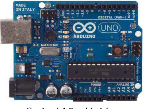
Gambar A.1 Board Arduino
The Arduino Uno is a microcontroller board based on the ATmega328 . It has 14 digital
input/output pins (of which 6 can be used as PWM outputs), 6 analog inputs, a
16 MHz crystal oscillator, a USB connection, a power jack, an ICSP header, and a reset
button. It contains everything needed to support the microcontroller; simply connect it to a
computer with a USB cable or power it with a AC-to-DC adapter or battery to get started.
The Uno differs from all preceding boards in that it does not use the FTDI USB-to-serial
driver chip. Instead, it features the Atmega16U2 (Atmega8U2 up to version R2) programmed
as a USB-to-serial converter.
"Uno" means one in Italian and is named to mark the upcoming release of Arduino 1.0. The
Uno and version 1.0 will be the reference versions of Arduino, moving forward. The Uno is
the latest in a series of USB Arduino boards, and the reference model for the Arduino
platform; for a comparison with previous versions, see the index of Arduino boards.
S u m ma r y
Microcontroller ATmega328
Operating Voltage 5V
Input Voltage (recommended) 7-12V
Input Voltage (limits) 6-20V
Digital I/O Pins 14 (of which 6 provide PWM output)
Analog Input Pins 6
DC Current per I/O Pin 40 mA
DC Current for 3.3V Pin 50 mA
Flash Memory 32 KB (ATmega328) of which 0.5 KB used by bootloader
EEPROM 1 KB (ATmega328)
Clock Speed 16 MHz
S c he ma t i c & R e f e r e nc e De s i g n
EAGLE files: arduino-uno-Rev3-reference-design.zip (NOTE: works with Eagle 6.0 and
newer)
Schematic: arduino-uno-Rev3-schematic.pdf
Note: The Arduino reference design can use an Atmega8, 168, or 328, Current models use
an ATmega328, but an Atmega8 is shown in the schematic for reference. The pin
configuration is identical on all three processors.
P o w e r
The Arduino Uno can be powered via the USB connection or with an external power supply.
The power source is selected automatically.
External (non-USB) power can come either from an AC-to-DC adapter (wall-wart) or battery.
The adapter can be connected by plugging a 2.1mm center-positive plug into the board's
power jack. Leads from a battery can be inserted in the Gnd and Vin pin headers of the
POWER connector.
The board can operate on an external supply of 6 to 20 volts. If supplied with less than 7V,
however, the 5V pin may supply less than five volts and the board may be unstable. If using
more than 12V, the voltage regulator may overheat and damage the board. The recommended
range is 7 to 12 volts.
The power pins are as follows:
VIN. The input voltage to the Arduino board when it's using an external power source (as opposed to 5 volts from the USB connection or other regulated power source). You can
supply voltage through this pin, or, if supplying voltage via the power jack, access it
through this pin.
5V.This pin outputs a regulated 5V from the regulator on the board. The board can be supplied with power either from the DC power jack (7 - 12V), the USB connector (5V),
or the VIN pin of the board (7-12V). Supplying voltage via the 5V or 3.3V pins bypasses
the regulator, and can damage your board. We don't advise it.
3V3. A 3.3 volt supply generated by the on-board regulator. Maximum current draw is 50 mA.
GND. Ground pins.
M e mo r y
The ATmega328 has 32 KB (with 0.5 KB used for the bootloader). It also has 2 KB of SRAM
I np ut a nd O ut p ut
Each of the 14 digital pins on the Uno can be used as an input or output,
using pinMode(), digitalWrite(), and digitalRead()functions. They operate at 5 volts. Each pin
can provide or receive a maximum of 40 mA and has an internal pull-up resistor
(disconnected by default) of 20-50 kOhms. In addition, some pins have specialized functions:
Serial: 0 (RX) and 1 (TX). Used to receive (RX) and transmit (TX) TTL serial data. These pins are connected to the corresponding pins of the ATmega8U2 USB-to-TTL
Serial chip.
External Interrupts: 2 and 3. These pins can be configured to trigger an interrupt on a low value, a rising or falling edge, or a change in value. See the attachInterrupt() function
for details.
PWM: 3, 5, 6, 9, 10, and 11. Provide 8-bit PWM output with the analogWrite() function. SPI: 10 (SS), 11 (MOSI), 12 (MISO), 13 (SCK). These pins support SPI communication
using the SPI library.
LED: 13. There is a built-in LED connected to digital pin 13. When the pin is HIGH value, the LED is on, when the pin is LOW, it's off.
The Uno has 6 analog inputs, labeled A0 through A5, each of which provide 10 bits of
resolution (i.e. 1024 different values). By default they measure from ground to 5 volts, though
is it possible to change the upper end of their range using the AREF pin and
the analogReference() function. Additionally, some pins have specialized functionality:
TWI: A4 or SDA pin and A5 or SCL pin. Support TWI communication using the Wire library.
There are a couple of other pins on the board:
AREF. Reference voltage for the analog inputs. Used with analogReference().
Reset. Bring this line LOW to reset the microcontroller. Typically used to add a reset button to shields which block the one on the board.
See also the mapping between Arduino pins and ATmega328 ports. The mapping for the
Atmega8, 168, and 328 is identical.
C o m m u n i c a t i o n
The Arduino Uno has a number of facilities for communicating with a computer, another
Arduino, or other microcontrollers. The ATmega328 provides UART TTL (5V) serial
communication, which is available on digital pins 0 (RX) and 1 (TX). An ATmega16U2 on
the board channels this serial communication over USB and appears as a virtual com port to
external driver is needed. However, on Windows, a .inf file is required. The Arduino software
includes a serial monitor which allows simple textual data to be sent to and from the Arduino
board. The RX and TX LEDs on the board will flash when data is being transmitted via the
USB-to-serial chip and USB connection to the computer (but not for serial communication on
pins 0 and 1).
A SoftwareSerial library allows for serial communication on any of the Uno's digital pins.
The ATmega328 also supports I2C (TWI) and SPI communication. The Arduino software
includes a Wire library to simplify use of the I2C bus; see the documentation for details. For
SPI communication, use the SPI library.
P r o g r a m mi ng
The Arduino Uno can be programmed with the Arduino software (download). Select
"Arduino Uno from the Tools > Board menu (according to the microcontroller on your
board). For details, see the reference and tutorials.
The ATmega328 on the Arduino Uno comes preburned with a bootloader that allows you to
upload new code to it without the use of an external hardware programmer. It communicates
using the original STK500 protocol (reference, C header files).
You can also bypass the bootloader and program the microcontroller through the ICSP
(In-Circuit Serial Programming) header; see these instructions for details.
The ATmega16U2 (or 8U2 in the rev1 and rev2 boards) firmware source code is available .
The ATmega16U2/8U2 is loaded with a DFU bootloader, which can be activated by:
On Rev1 boards: connecting the solder jumper on the back of the board (near the map of Italy) and then resetting the 8U2.
On Rev2 or later boards: there is a resistor that pulling the 8U2/16U2 HWB line to ground, making it easier to put into DFU mode.
You can then use Atmel's FLIP software (Windows) or the DFU programmer (Mac OS X and
Linux) to load a new firmware. Or you can use the ISP header with an external programmer
(overwriting the DFU bootloader). See this user-contributed tutorial for more information.
A ut o ma t i c ( S o f t wa r e ) R e s e t
Rather than requiring a physical press of the reset button before an upload, the Arduino Uno
is designed in a way that allows it to be reset by software running on a connected computer.
One of the hardware flow control lines (DTR) of theATmega8U2/16U2 is connected to the
reset line of the ATmega328 via a 100 nanofarad capacitor. When this line is asserted (taken
low), the reset line drops long enough to reset the chip. The Arduino software uses this
capability to allow you to upload code by simply pressing the upload button in the Arduino
environment. This means that the bootloader can have a shorter timeout, as the lowering of
This setup has other implications. When the Uno is connected to either a computer running
Mac OS X or Linux, it resets each time a connection is made to it from software (via USB).
For the following half-second or so, the bootloader is running on the Uno. While it is
programmed to ignore malformed data (i.e. anything besides an upload of new code), it will
intercept the first few bytes of data sent to the board after a connection is opened. If a sketch
running on the board receives one-time configuration or other data when it first starts, make
sure that the software with which it communicates waits a second after opening the
connection and before sending this data.
The Uno contains a trace that can be cut to disable the auto-reset. The pads on either side of
the trace can be soldered together to re-enable it. It's labeled "RESET-EN". You may also be
able to disable the auto-reset by connecting a 110 ohm resistor from 5V to the reset line;
see this forum thread for details.
U S B Ov e r c ur r e nt P r ot e c t i o n
The Arduino Uno has a resettable polyfuse that protects your computer's USB ports from
shorts and overcurrent. Although most computers provide their own internal protection, the
fuse provides an extra layer of protection. If more than 500 mA is applied to the USB port, the
fuse will automatically break the connection until the short or overload is removed.
P hy s i c a l C ha r a c t e r i s t i c s
The maximum length and width of the Uno PCB are 2.7 and 2.1 inches respectively, with the
USB connector and power jack extending beyond the former dimension. Four screw holes
allow the board to be attached to a surface or case. Note that the distance between digital pins
LAMPIRAN B
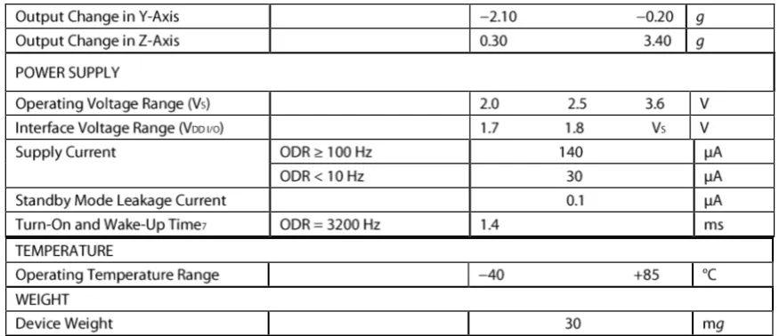
AKSELEROMETER ADXL 345
FEATURES
Ultralow power: as low as 23 μA in measurement mode and 0.1 μA in standby mode at VS = 2.5 V (typical) Power consumption scales automatically with bandwidth
User-selectable resolution
Fixed 10-bit resolution
Full resolution, where resolution increases with g range, up to 13-bit resolution at ±16 g
(maintaining 4 mg/LSB scale factor in all g ranges)
Patent pending, embedded memory management system with FIFO technology minimizes host
processor load
Single tap/double tap detection
Activity/inactivity monitoring
Free-fall detection
Supply voltage range: 2.0 V to 3.6 V
I/O voltage range: 1.7 V to VS SPI (3- and 4-wire) and I2C digital interfaces
Flexible interrupt modes mappable to either interrupt pin
Measurement ranges selectable via serial command
Bandwidth selectable via serial command Wide temperature range (−40°C to +85°C) 10,000 g shock survival
Pb free/RoHS compliant
Small and thin: 3 mm × 5 mm × 1 mm LGA package
APPLICATIONS
Handsets
Medical instrumentation
Gaming and pointing devices
Industrial instrumentation
Personal navigation devices
ABSOLUTE MAXIMUM RATINGS
Stresses above those listed under Absolute Maximum Ratings may cause permanent damage to the device. This is a stress rating only; functional operation of the device at these or any other conditions above those indicated in the operational section of this specification is not implied. Exposure to absolute maximum rating conditions for extended periods may affect device reliability.
PIN CONFIGURATION AND FUNCTION DESCRIPTIONS
POWER SAVINGS
SERIAL COMMUNICATIONS
Due to communication speed limitations, the maximum output data rate when using 400 kHz I2C is 800 Hz and scales linearly with a change in the I2C communication speed. For example, using I2C at 100 kHz would limit the maximum ODR to 200 Hz. Operation at an output data rate above the recommended maxi-mum may result in undesirable effect on the acceleration data, including missing samples or additional noise.
proper I2C operation. Refer to the UM10204 I2C-Bus Specification and User Manual, Rev. 03—19 June
2007, when selecting pull-up resistor values to ensure proper operation.
LAMPIRAN C
MAGNETOMETER - HMC5883L
The Honeywell HMC5883L is a surface-mount, multi-chip module designed for low-field magnetic sensing with a digital interface for applications such as low-cost compassing and magnetometry. The HMC5883L includes our state-of-the-art, high-resolution HMC118X series magneto-resistive sensors plus an ASIC containing amplification, automatic degaussing strap drivers, offset cancellation, and a 12-bit ADC that enables 1° to 2° compass heading accuracy. The I2C serial bus allows for easy interface. The HMC5883L is a 3.0x3.0x0.9mm surface mount 16-pin leadless chip carrier (LCC).
Applications for the HMC5883L include Mobile Phones, Netbooks, Consumer Electronics, Auto Navigation Systems, and Personal Navigation Devices.
The HMC5883L utilizes Honeywell’s Anisotropic Magnetoresistive (AMR) technology
that provides advantages over other magnetic sensor technologies. These anisotropic, directional sensors feature precision in-axis sensitivity and linearity. These sensors’ solid -state construction with very low cross-axis sensitivity is designed to measure both the
direction and the magnitude of Earth’s magnetic fields, from milli-gauss to 8 gauss.
Honeywell’s Magnetic Sensors are among the most sensitive and reliable low-field sensors in the industry.
LAMPIRAN D
MOTOR SERVO
MG995 Servo Digital de Alta Velocidad y Torque Voltage recomendable: 3.5 - 8.4 Volts , nominal 5 volts.
Dimension:
Velocidad de Operación (4.8V sin carga): Velocidad de Operación (6V sin carga):
Torque de parada (4.8V): Torque de Parada (6.0V):
Mass: 55.2g Range Temperature:
1.57" x 0.79" x 1.44" (40 x 20 x 36.5mm) 1.78oz (48g)
0.17seg / 60 s 0.13seg / 60 s
(13kg/cm) (15kg/cm) -30 to +60 C
| 1
BAB I
PENDAHULUAN
Pada bab ini terdapat latar belakang, identifikasi masalah, perumusan masalah, tujuan, pembatasan masalah, metodologi, spesifikasi alat, pembatasan masalah dan sistematika penulisan.
1.1Latar Belakang
Dalam dunia industri, sering dijumpai kebutuhan human interface pengendali lengan robot untuk keperluan memindahkan barang-barang yang berbahaya jika langsung menggunakan tangan.
Human interface berupa gesture dapat digunakan untuk
membantu pengguna dalam berinteraksi dengan robot secara gerakan tubuh, misalnya gerakan lengan robot yang meniru gerakan lengan manusia. Gerakan lengan manusia ini akan dideteksi oleh satu atau beberapa sensor yang terpasang pada sarung tangan yang digunakan oleh manusia tersebut, misalnya berupa akselerometer atau magnetometer karena keduanya dapat mendeteksi orientasi berupa gerak rotasi. Kemudian informasi dari sensor tersebut diproses untuk menentukan sinyal yang tepat untuk aktuator(motor) yang akan menggerakkan lengan robot.
Gerakan robot diperlukan untuk memanipulasi suatu benda,
seperti mengambil, mengubah, atau menghancurkan. Maka “hand” dari robot
dikategorikan sebagai end effector, sedangkan "arm" sebagai manipulator.
Arm ini yang biasa disebut dengan lengan robot. [12]
Proses pengolahan informasi pada robot umumnya dilakukan melalui mikrokontroler. Mikrokontroler biasanya digunakan dan dipasang pada sebuah board, misalnya Arduino. Arduino merupakan sebuah modul mikrokontroler open-source yang terdiri dari board sederhana yang menggunakan mikrokontroler ATMEGA yang diprogram dengan development
1.2Identifikasi Masalah
Identifikasi masalah pada Tugas Akhir ini adalah perancangan dan realisasi lengan robot tiga derajat kebebasan menggunakan sensor akselerometer ADXL345 dan Arduino.
1.3 Perumusan Masalah
Perumusan masalah dalam Tugas Akhir ini yaitu:
Bagaimana cara merancang dan merealisasikan lengan robot tiga derajat kebebasan menggunakan sensor akselerometer ADXL345 dan Arduino?
1.4 Tujuan
Tujuan dari Tugas Akhir ini adalah merancang dan merealisasikan lengan robot tiga derajat kebebasan menggunakan sensor akselerometer ADXL345 dan Arduino.
1.5 Pembatasan Masalah
Pada pembuatan Tugas Akhir ini, pembatasan masalahnya adalah sebagai berikut:
1. Sensor akselerometer ADXL345, magnetometer HMC5883L, dan
switch dipasang pada sarung tangan yang digunakan pengguna.
2. Lengan robot yang dibuat memiliki tiga derajat kebebasan yang terdiri dari base rotation, elbow flex dan wrist yaw.
3. Gerakan lengan robot mengikuti gerakan lengan pengguna yaitu: a. gerakan base rotation berdasarkan gerakan rotasi siku, b. gerakan elbow flex berdasarkan gerakan flex siku,
c. gerakan wrist yaw berdasarkan gerakan ke sisi pergelangan tangan.
| 3
1.6 Metodologi
Metodologi dalam Tugas Akhir ini adalah dengan eksperimental sehingga hasilnya dapat diuji. Langkah-langkahnya adalah :
1. mempelajari modul dan software Arduino,
2. mengimplementasikan bahasa C (IDE Arduino) pada modul Arduino, 3. membuat rangka akrilik untuk lengan robot dan memasang servo sebagai
sendinya,
4. mempelajari akselerometer ADXL345 dan magnetometer HMC5883L, 5. melakukan percobaan untuk mengetahui akselerometer ADXL345 dan
magnetometer HMC5883L berfungsi dengan baik atau tidak,
6. memetakan pergerakan ADXL345 yang tertempel pada tangan, yang dibaca oleh Arduino,
7. memetakan pergerakan HMC5883L yang tertempel pada tangan, yang dibaca oleh Arduino
8. membuat program untuk menggerakkan lengan robot sesuai dengan pergerakan ADXL dan magnetometer,
9. menguji keberhasilan dan mengambil data pergerakan lengan terhadap nilai sensor,
10.menguji keberhasilan pergerakan lengan robot saat mencapit dan memindahkan barang serta mengambil data pergeseran dan simpangannya.
1.7Spesifikasi Alat
Spesifikasi alat yang digunakan pada tugas akhir ini adalah: 1. Akselerometer ADXL345
2. Magnetometer HMC5883L 3. Baterai LIPO 7,4 V, 2200mA
4. Board Arduino Uno dengan ATMEGA328
5. Software Arduino - IDE Arduino
6. Motor servo Futaba S3003 7. Motor servo Towerpro MG995
9. Tactile push button switch normally open
10. Body lengan yang terbuat dari akrilik
1.8Sistematika Penulisan
Sistematika penulisan dalam pembahasan laporan tugas akhir ini disusun menjadi lima bab, yaitu:
1. Bab I PENDAHULUAN
Bab ini berisi latar belakang, identifikasi masalah, perumusan masalah, tujuan, pembatasan masalah, metodologi, spesifikasi alat dan sistematika penulisan.
2. Bab II LANDASAN TEORI
Bab ini berisi teori yang akan digunakan untuk merancang dan merealisasikan aplikasi akselerometer ADXL345 dan Arduino untuk lengan robot dengan tiga derajat kebebasan yang meliputi pembahasan robotika, Arduino, akselerometer ADXL345, magnetometer HMC5883L, motor servo, dan tactile push button
switch.
3. Bab III PERANCANGAN
Bab ini berisi perancangan dan realisasi aplikasi akselerometer ADXL345 dan Arduino untuk lengan robot dengan tiga derajat kebebasan yang terdiri dari diagram blok perancangan, perancangan
hardware dan software.
4. Bab IV DATA PENGAMATAN DAN ANALISIS
Bab ini berisi pengamatan gerakan lengan robot, data pengamatan dan analisis data yang diperoleh dari lengan robot yang telah dibuat.
5. Bab V KESIMPULAN DAN SARAN
| 44 Universitas Kristen Maranatha
BAB V
KESIMPULAN DAN SARAN
Bab ini berisikan kesimpulan akhir sekaligus beberapa saran yang dirasa perlu dan bermanfaat untuk pengembangan lebih lanjut.
5.1 Kesimpulan
Dengan memperhatikan data pengamatan dan analisis pada bab sebelumnya, dapat disimpulkan beberapa hal di bawah ini:
1. Hasil realisasi lengan robot dengan tiga derajat kebebasan, memiliki keberhasilan yang terlihat dari lengan robot yang mengikuti lengan pengguna dengan simpangan yang terjadi pada elbow flex(x) yaitu berkisar antara 0º-9º, simpangan yang terjadi pada saat gerakan wrist yaw(y) yaitu berkisar antara 2º-15º dan simpangan yang terjadi pada saat gerakan base rotation(z) yaitu berkisar antara 0º-20º.
2. Pencapitan dan pemindahan barang berdasarkan posisi awal dan posisi akhir gerakan base rotation lengan pengguna yang dibaca sensor dibandingkan dengan posisi akhir lengan robot memiliki simpangan berkisar antara 0º-20º. 3. Jangkauan maksimal pada gerakan elbow flex untuk pencapitan barang adalah
yang memiliki ketinggian minimal 17 cm dengan kemiringan terhadap permukaan lengan robot tidak kurang dari 30º dan tidak lebih dari 150º.
5.2 Saran
Saran yang dapat diberikan untuk perbaikan dan pengembangan dari Tugas Akhir ini yaitu:
1. Ditambahkan feedback sensor atau sistem kontrol close loop untuk memperkecil simpangan pada setiap gerakan lengan.
DAFTAR PUSTAKA
4. “Arduino Introduction” N.p., n.d. Web. 21 Maret 2012
<http://arduino.cc/en/Guide/Introduction>
5. “Arduino Uno” N.p., n.d. Web. 27 September 2012.
<http://arduino.cc/en/Main/ArduinoBoardUno> N.p., n.d. Web. 21 September 2012.
<https://www.loveelectronics.co.uk/products/156/dip-tactile-button-switch>
9. “HMC5883L Compass Tutorial with Arduino Library” N.p., n.d. Web. 11
September 2012.
<https://www.loveelectronics.co.uk/Tutorials/8/hmc5883l-tutorial-and-arduino-library>
10. “Pendahuluan Robotika” N.p., n.d. Web. 11 November 2012.
http://didiktristianto.dosen.narotama.ac.id/files/2011/09/pengenalan-robot.pdf
11. Andrianto, Heri. 2008. “Pemrograman Mikrokontroler AVR Atmega16”.
12.“Robotics” N.p., N.d. Web. 5 Desember 2012. <http://en.wikipedia.org/wiki/Robotics>
13. “S3003 Futaba Servo” N.p., n.d. Web 27 Oktober 2012.
<http://www.es.co.th/schemetic/pdf/et-servo-s3003.pdf>
14.“Tilt Compensating a Compass with an Accelerometer” N.p., n.d. Web. 11
September 2012.
<https://www.loveelectronics.co.uk/Tutorials/13/tilt-compensated-compass-arduino-tutorial>
15.“TowerPro MG995 Alta Velocidad & Torque, Servo Digital” N.p., N.d.
Web. 11 November 2012.
<http://roboeq.com/PDF/0102002.pdf - mg995>
16. “ 3-Axis Digital Compass IC HMC5883L” N.p., n.d. Web. 5 Oktober 2012.
<http://www51.honeywell.com/aero/common/documents/myaerospacecata