SPATIO-SEMANTIC COMPARISON OF LARGE 3D CITY MODELS IN CITYGML
USING A GRAPH DATABASE
S. H. Nguyen, Z. Yao, T. H. Kolbe
Technical University of Munich (TUM), Dept. of Civil, Geo and Environmental Engineering, D80333 Munich, Germany -(son.nguyen, zhihang.yao, thomas.kolbe)@tum.de
KEY WORDS:CityGML, Spatio-semantic Comparison, Change Detection, Graph Database, Web Feature Service
ABSTRACT:
A city may have multiple CityGML documents recorded at different times or surveyed by different users. To analyse the city’s evolution over a given period of time, as well as to update or edit the city model without negating modifications made by other users, it is of utmost importance to first compare, detect and locate spatio-semantic changes between CityGML datasets. This is however difficult due to the fact that CityGML elements belong to a complex hierarchical structure containing multi-level deep associations, which can basically be considered as a graph. Moreover, CityGML allows multiple syntactic ways to define an object leading to syntactic ambiguities in the exchange format. Furthermore, CityGML is capable of including not only 3D urban objects’ graphical appearances but also their semantic properties. Since to date, no known algorithm is capable of detecting spatio-semantic changes in CityGML documents, a frequent approach is to replace the older models completely with the newer ones, which not only costs computational resources, but also loses track of collaborative and chronological changes. Thus, this research proposes an approach capable of comparing two arbitrarily large-sized CityGML documents on both semantic and geometric level. Detected deviations are then attached to their respective sources and can easily be retrieved on demand. As a result, updating a 3D city model using this approach is much more efficient as only real changes are committed. To achieve this, the research employs a graph database as the main data structure for storing and processing CityGML datasets in three major steps: mapping, matching and updating. The mapping process transforms input CityGML documents into respective graph representations. The matching process compares these graphs and attaches edit operations on the fly. Found changes can then be executed using the Web Feature Service (WFS), the standard interface for updating geographical features across the web.
1. INTRODUCTION
As an official OGC standard for encoding virtual 3D city mod-els, CityGML opens up opportunities for applications in a broad range of areas such as urban planning, facility management, en-vironmental simulations and thematic inquiries. One of the main factors contributing to this success is CityGML’s capability of in-cluding not only 3D urban objects’ graphical appearances, but also their semantic properties (e.g. relationships between objects). This ensures CityGML documents can be shared over various applica-tions that make use of the model’s common semantic information, which is “especially important with respect to the cost-effective sustainable maintenance of 3D city models” (Gröger et al., 2012).
However, although the increasing number of CityGML datasets in recent years indicates a positive sign of the open standard’s steady growth, it has also been a great challenge to maintain sus-tainable 3D city models. One prominent example is the difficulty of handling undocumented collaborative as well as chronological changes of an existing city model, which is currently unavoidable due to the fact that as cities grow over time, so does the need to ad-just their models accordingly (Navratil et al., 2010). Furthermore, because the current state of CityGML does not store these changes in its instances, multiple model documents of the same city may accumulate over time. As a result, during the maintenance phase, old city datasets are overwritten completely by newer ones, which not only costs a large amount of time and computational resources, but also loses track of collaborative changes and neglects the city’s progress recorded during the given time period. Moreover, replac-ing entire large datasets due to only some small changes would cause an unnecessarily huge volume of transactions, especially if the database is managed via the Web Feature Service (WFS).
Therefore, instead of replacing older records, an ideal alternative should first compare the models, then attach edit operations to detected deviations, based on which only real changes are commit-ted. This way, older datasets can both be updated and still retain their respective core structure, including own rules of syntax and internal object references. This plays a key role in enabling a version control system for collaborative work in modelling and storing digital 3D city models (Chaturvedi et al., 2015). Moreover, the number of transactions required for a WFS-enabled database is also reduced significantly.
In order to achieve this, the first task is to determine key aspects, based on which CityGML models should be compared. Since “one of the most important design principles for CityGML is the coherent modelling of semantics and geometrical/topological prop-erties” (Gröger et al., 2012), a comparison between two CityGML instances should take into account both their geometrical and semantic aspects to ensure reliable results. For example, wall sur-faces can be defined in-line or referenced to other existing walls of surrounding buildings via the XML Linking Language (XLink). Thus, the further question arises as to how geometrical and se-mantic information of CityGML documents can be compared. Considering the facts that CityGML elements belong to a complex graph-like structure, syntactic ambiguities (such as between XLink and in-line objects) can be disambiguated using a graph. Since CityGML documents can be very large in size, an approach to detect spatio-semantic changes in arbitrarily large-sized CityGML datasets utilizing a graph database is proposed.
and 5) and updating an existing CityGML database based on detected deviations (Section 6). An example of the proposed approach is introduced in Section 7. Section 8 further presents the results of some experiments conducted in this research. At the end, Section 9 summarizes and concludes the paper.
2. RELATED WORK
Conventional❞✐❢❢tools, such as the Hunt–McIlroy algorithm (Hunt and McIlroy, 1976), are only able to find deviations in pure texts and thus not compatible with highly structured data models employed in Geographic Information System (GIS). Bakillah et al., 2009 proposed a conceptual basis for a semantic similarity model (Sim-Net) for ad hoc network based on the multi-view paradigm. Olteanu et al., 2006 addressed the automatic matching of imper-fect geospatial data during database integration. However, since each of these researches mainly focused on either the semantic or geometrical aspect of city objects, they are not fully applicable to CityGML, which provides an integrated view of both aspects.
Later, Redweik and Becker, 2015 presented a concept for detect-ing semantic and geometrical changes in CityGML documents. Since CityGML is an application schema of XML, which is a tree data structure, by assuming that CityGML instances can also be represented as trees, they extended the algorithm “X-Diff” (Wang et al., 2003) that considers tree equivalence as isomorphism. How-ever, in contrast to XML, CityGML is not a tree but a graph data structure by definition, as it may contain cycles and nodes linked by multiple parents (e.g. due to XLinks). Therefore, this approach is generally not expressive enough regarding CityGML’s graph data structure. Moreover, the methods proposed by Redweik and Becker, 2015 are not yet evaluated against massive input datasets.
To deal with large input datasets, the ability to efficiently preselect potential matching candidates based on their spatial properties is of advantage. Topologically relative allocations of objects can be expressed by the “4” or “9-intersection model” (“4-IM” or “9-IM”) (Egenhofer and Franzosa, 1991; Egenhofer and Herring, 1991). Moreover, an object can be localized by recursively dividing its parent graph into quadtrees (2D) or octrees (3D) and colouring their interior as well as exterior (Berg et al., 2008). Alternatively, an R-tree can be applied to spatial objects grouped in regions based on their topological properties (Guttman, 1984). Since R-trees are balanced, their query response time in logarithmic time complexityO(logMn)is very efficient in large databases, where
Mis the maximum number of entries allowed per internal node.
Old CityGML
dataset
New CityGML
dataset
map
Graph match Graph
update
Graph database
map
Figure 1. An overview of three major steps mapping, matching and updating of 3D city models using a graph database.
3. MAPPING 3D CITY MODELS ONTO A GRAPH DATABASE
The overall implementation consists of three major parts as shown in Figure 1, in all of which the graph databaseNeo4jis employed. In Neo4j, each city object is stored as a graph node, while the rela-tionships between these objects are represented as edges between
nodes. In other words, nodes are connected directly to each other. This is particularly useful in data models that have a complex and multi-level deep hierarchical structure like CityGML. In this section, the mapping of city objects onto Neo4j graphs shall be explained in several smaller steps.
3.1 Reading CityGML Datasets in Java
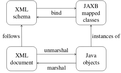
CityGML documents can be processed with the help of various XML parsing APIs in Java such as the Document Object Model (DOM), Simple API for XML (SAX), Streaming API for XML (StAX) or Java Architecture for XML Binding (JAXB). Each API comes with their own advantages and disadvantages depending on the application domain. Considering the fact that CityGML datasets can grow quickly in size, the librarycitygml4jemploys a combination of JAXB and SAX (Nagel, 2017), which allows par-tial unmarshalling (or deserialization) of CityGML elements into Java objects with efficient memory consumption (see Figures 2 and 3a). Moreover, this approach provides an object-oriented view of read CityGML data, which facilitates the transformation of unmarshalled Java objects to graph entities in the next step.
XML schema
XML document
JAXB mapped
classes
Java objects marshal
unmarshal follows
bind
instances of
Figure 2. The JAXB binding process. Adapted from Oracle Corporation, 2015.
3.2 Converting Java Objects to Graph Entities
To transform previously unmarshalled Java objects to correspond-ing graph entities in Neo4j conservcorrespond-ing as much data as possible (see Figure 3a), theNeo4j Java Core APIis employed. Concep-tually however, two major challenges arise. Firstly, unmarshalled Java instances belong to a complex class hierarchy defined by the XML schema of CityGML. This poses the difficulty in de-signing suitable graph structures, such as how to efficiently rep-resent different instances of the same class. Secondly, Neo4j is a value-based graph database, which means that no explicit schema modelling is possible. As a result, compared to XML-structure, it is difficult to map Java objects onto graph entities without losing any information, especially their hierarchical inheritance relations.
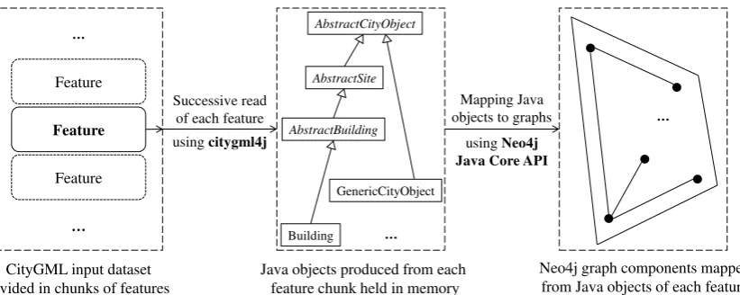
CityGML input dataset divided in chunks of features
Feature
Feature
Feature
Successive read of each feature
Java objects produced from each feature chunk held in memory
using citygml4j AbstractBuilding
Building AbstractSite
AbstractCityObject
GenericCityObject
Mapping Java objects to graphs
using Neo4j Java Core API
Neo4j graph components mapped from Java objects of each feature
(a) Unmarshalling CityGML documents and mapping Java objects onto graphs.
Mapped features as unconnected sub-graphs
Retrieve nodes containing hrefs
and IDs
Connected feature sub-graphs based on found IDs and hrefs
using indexing
or ahashmap
Compute bbox of connected city object
using customized citygml4j
bbox function
Connected city object and its bounding box
(b) Resolving XLinks and computing minimum bounding boxes (as a preparation for the matching process).
Figure 3. An overview of the mapping process.
Algorithm 1:♠❛♣(✐♥st❛♥❝❡,❝♦♥t❛✐♥❡r) Input :A Java✐♥st❛♥❝❡
Output :Created node in a graph database
1 if❝♦♥t❛✐♥❡r is♥✉❧❧ then 2 create a♥♦❞❡ in graph database;
3 set♥♦❞❡.❧❛❜❡❧ equal to✐♥st❛♥❝❡.❝❧❛ss◆❛♠❡;
4 set❝♦♥t❛✐♥❡r equal to this♥♦❞❡;
5 end
6 initialize❛ttr✐❜✉t❡sas a set oflocalattributes and references of✐♥st❛♥❝❡;
7 foreach❛ttr✐❜✉t❡ of ❛ttr✐❜✉t❡sdo
8 if❛ttr✐❜✉t❡ can be stored as simple textsthen
9 store❛ttr✐❜✉t❡ as a property in❝♦♥t❛✐♥❡r;
10 else
11 create a❝❤✐❧❞ node via♠❛♣ ✭❛ttr✐❜✉t❡,♥✉❧❧ ✮;
12 create a relationship from❝♦♥t❛✐♥❡r to❝❤✐❧❞;
13 end
14 end
15 if✐♥st❛♥❝❡ inherits❙✉♣❡r❈❧❛ss then
16 call♠❛♣ ✭(❙✉♣❡r❈❧❛ss)✐♥st❛♥❝❡,❝♦♥t❛✐♥❡r ✮;
17 end
18 return❝♦♥t❛✐♥❡r;
3.3 Connecting Mapped City Objects using XLinks
Section 3.1 addresses the problems of parsing large CityGML documents concerning memory consumption and proposes an ap-proach dividing them into smaller feature chunks. Each chunk is then separately unmarshalled and consequently mapped onto sub-graphs in Neo4j as described in Section 3.2. As a result, the explicit connections between split features and their respective par-ent elempar-ents are lost during the process (see Figure 3b). To allow the subsequent recovery of severed connections, before splitting, the library citygml4j stores IDs of affected features in XLinks (or ❤r❡❢s) and attaches them to respective parent elements. XLink is a simple yet practical means to referencing or reusing existing elements without having to define them “in-line” repeatedly and thus essentially reduces redundancies in XML documents (Bray et al., 2008; DeRose et al., 2010). However, despite their syntactic differences, both XLink and in-line declaration are often used to effectively define the same objects.
GRID
GRID_ LIMITS
STRING_ OR_REF
META_DATA_ PROPERTY
META_DATA_ PROPERTY
CODE
CODE metaDataProp
metaDataProp
name
name description gridLimits
id axisLabels
gid srsDimension
srsName uomLabels
axisName dimension
AbstractGML AbstractGeometry
Grid
Successive mapping according to class hierarchy:
Figure 4. An example of a graph representing a●r✐❞object. Rounded rectangles represent nodes. Node properties are displayed below nodes’ label. The colours indicate the originating classes, in which nodes and properties are defined. The container
●❘■❉node is expanded successively for each superclass.
the fly. Then, XLinks can be resolved by linking indexed❤r❡❢s and IDs. Internal hash maps offer fast response time but come at the cost of memory consumption. On the contrary, Neo4j indices require less memory but may slow down the mapping process due to costly disk read and write operations. Moreover, sufficient additional storage space must also be reserved beforehand.
3.4 Calculating Minimum Bounding Boxes of Buildings
Ideally, in citygml4j, the minimum bounding box of a spatial Java city object (e.g.❇✉✐❧❞✐♥❣) can be computed by a built-in func-tion that considers all of its geometric contents (e.g. boundary surfaces). However, this method has some limitations. Firstly, input Java objects must be completely available in memory as a whole, which is not always the case, since Section 3.1 shows that large city objects are to be split into features. Secondly, if Java objects have unresolvable XLinks (such as those contained in not yet loaded features), the function may fail. Thus, to overcome these limitations, graph representations, which are now connected and syntactically disambiguated as a result of Section 3.3, are reversely transformed to Java objects, from which respective mini-mum bounding boxes are calculated using the built-in function.
4. MATCHING 3D CITY MODELS USING GRAPH DATABASE
Since nodes play a central role in graphs, the matching process is based around the concept of their structure. In other words, two graphs can be matched by recursively comparing the properties and relationships of all of their respective nodes.
4.1 Comparing Node Properties
Actual data are mostly stored in node properties. Thus, differences found in node properties indicate possible deviations of respec-tive data sources. Values from the same unique property name are compared with one another potentially followed by an update oper-ation. Unmatched properties from the older and newer city model shall be attached with delete and insert operations respectively. An overview of all edit operations is shown in Section 6.1.
4.2 Matching Node Relationships
Matching relationships between two given nodes is complex con-sidering the fact that relationships in Neo4j can be processed in both directions, namely❖❯❚●❖■◆●and■◆❈❖▼■◆●. The matching process must however remain consistent in one specific traversing direction, so that no node is processed twice. The chosen direction is❖❯❚●❖■◆●, as the matching process starts with root nodes. In contrast to node properties, a relationship may occur multiple times for a given node (i.e. 1 to n, n to 1 and n to n relationships).
Taking these into account, Algorithm 2 describes the main concept of matching relationships of two given nodes, where the function ❢✐♥❞❴❝❛♥❞✐❞❛t❡in Line 5 plays a decisive role in terms of both efficiency and correctness of the whole matching process, as it dictates which object pairs should be compared to one another based on their specific characteristics. In CityGML, the most important aspect that can be used as a matching pattern among objects is their geometrical properties as well as spatial extents.
Algorithm 2:♠❛t❝❤❴r❡❧❛t✐♦♥s❤✐♣s✭♥♦❞❡✶✱ ♥♦❞❡✷✮ Input :♥♦❞❡✶ and♥♦❞❡✷ of graphs representing nodes of
old and new city model respectively
1 foreachmatchedr❡❧❴t②♣❡ of ♥♦❞❡✶ and♥♦❞❡✷ do 2 ❝❤❞r✶ ←♥♦❞❡✶.❣❡t❴❝❤✐❧❞r❡♥ ✭r❡❧❴t②♣❡ ✮;
3 ❝❤❞r✷ ←♥♦❞❡✷.❣❡t❴❝❤✐❧❞r❡♥ ✭r❡❧❴t②♣❡ ✮; 4 foreach❝❤✐❧❞✶ of ❝❤❞r✶ do
5 ❝❤✐❧❞✷ ←❝❤❞r✷.❢✐♥❞❴❝❛♥❞✐❞❛t❡ ✭❝❤✐❧❞✶ ✮;
6 if❝❤✐❧❞✷ is not emptythen
7 ♠❛t❝❤❴♥♦❞❡ ✭❝❤✐❧❞✶,❝❤✐❧❞✷ ✮;
8 end
9 end
10 foreachunmatched❝❤✐❧❞✶ of❝❤❞r✶ do 11 create a❉❊▲❊❚❊operation;
12 end
13 foreachunmatched❝❤✐❧❞✷ of❝❤❞r✷ do 14 create an■◆❙❊❘❚operation;
15 end
16 end
17 foreachunprocessedr❡❧❴t②♣❡ of ♥♦❞❡✶ do 18 ❝❤❞r✶ ←♥♦❞❡✶.❣❡t❴❝❤✐❧❞r❡♥ ✭r❡❧❴t②♣❡ ✮; 19 foreach❝❤✐❧❞✶ of ❝❤❞r✶ do
20 create a❉❊▲❊❚❊operation;
21 end
22 end
23 foreachunprocessedr❡❧❴t②♣❡ of ♥♦❞❡✷ do
24 ❝❤❞r✷ ←♥♦❞❡✷.❣❡t❴❝❤✐❧❞r❡♥ ✭r❡❧❴t②♣❡ ✮; 25 foreach❝❤✐❧❞✷ of ❝❤❞r✷ do
26 create an■◆❙❊❘❚operation;
27 end
28 end
4.2.1 Matching Geometry of Points Points are a primitive notion, upon which all other geometric objects are built. Since points do not have length, area or volume, the only property em-ployed to distinguish them from others is their coordinates. In practice, however, real-world coordinates of the same point lo-cation may differ if they are given in different Spatial Reference Systems (SRS). Therefore, input CityGML instance documents should first be provided in the same spatial reference system.
to numerical (such as rounding) and instrument errors. Such minor deviations should be tolerated. Thus, for a reference pointP1as centre, depending on the chosen distance indicator, a neighbour-hoodN(ǫ)is constructed, whereǫis the maximum empirically predetermined allowed distance tolerance. For example, if the Euclidean distance indicator is chosen,N(ǫ)shall be a circle (2D) or a sphere (3D). However, to calculate this distance, expensive operations such as square roots and multiplications are required. Since the research focuses on matching 3D objects of massive datasets, for a smallǫ, it is often sufficient to compare coordinates in each dimension, which requires only subtractions. In this case,
N(ǫ)shall be a square (2D) or a cube (3D) (see Figure 5). A point
P2is geometrically matched with pointP1if, and only if,P2is located inside ofN(ǫ)ofP1. Two geometrically matched points are equal and thus no further comparison is needed.
ϵ ϵ
P1 P2
P3
x3 x1 x2 y1
y2 y3
x y
O
(a)N(ǫ)as a square in 2D.
ϵ ϵϵ
P1 P2
P3
x
z y
O
(b)N(ǫ)as a cube in 3D.
Figure 5. An illustration of the neighbourhoodN(ǫ)of pointP1 in 2D (5a) and 3D (5b).P1is matched withP2.
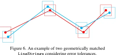
4.2.2 Matching Geometry of Line Segments Since line seg-ments (or▲✐♥❡❙tr✐♥❣s) are composed of points, they can be geometrically matched by iterating over all control points and ex-amining their spatial similarities successively with error tolerance ǫtaken into account (see Figure 6). Consecutive collinear line segments (given an empirically predetermined distance tolerance) can be merged together and thus treated as a single segment dur-ing matchdur-ing. Alternatively, two▲✐♥❡❙tr✐♥❣scan be matched using the Buffer Overlay Statistics (BOS) methods (Tveite, 1999). Geometrically matched▲✐♥❡❙tr✐♥❣sare considered equal.
Figure 6. An example of two geometrically matched ▲✐♥❡❙tr✐♥❣sconsidering error tolerances.
A more general concept of▲✐♥❡❙tr✐♥❣sis curves, each of whose curve segments may have a different interpolation method. A curve has a positive orientation. However, as long as such curves are composed of points, the same approach can be applied.
4.2.3 Matching Geometry of 3D Rings A ring in CityGML can be thought of as a closed▲✐♥❡❙tr✐♥❣described in Sec-tion 4.2.2. Buildings in CityGML make extensive use of poly-gons (Section 4.2.4), whose boundaries are often represented as ▲✐♥❡❛r❘✐♥❣s(Cox et al., 2004; Gröger et al., 2012; Gröger, 2010). Although a▲✐♥❡❛r❘✐♥❣can theoretically consist of non-planar points, only non-planar▲✐♥❡❛r❘✐♥❣sare considered.
The geometric comparisons of rings can be performed with the help of the libraries Abstract Window Toolkit (AWT) or Java Topology Suite (JTS). However, both of them are only applicable in two-dimensional space. Therefore, normal vectors (or orienta-tions) of 3D rings are first computed and compared. Only rings that have similar orientations (given an empirically predetermined angle tolerance) are rotated to a plane parallel to a predefined reference one using a rotation matrix as illustrated in Figure 7. Then, their shapes are compared regardless of numbers or orders of contained points. Two shapes are geometrically equal if they “fuzzily” contain each other’s points considering error toleranceǫ.
Rotation matrix
Figure 7. Rotating 3D (planar) ring.
4.2.4 Matching Geometry of 3D Polygons Polygons are ex-tensively used in CityGML as a means to describe surfaces of buildings and building parts. A polygon consists of exactly one exterior and an arbitrary number of interiors, all of which are rings and must be on the same plane. While an exterior defines the outline, interiors define holes in a polygon (Cox et al., 2004; Gröger et al., 2012; Gröger, 2010).
Therefore, a polygon can be thought of as a shape bounded by an exterior with all interiors subtracted from its inner area. The geometric comparison of two polygons is then performed in the same manner as in Section 4.2.3. This can also be extended for the comparison of❙✉r❢❛❝❡,❖r✐❡♥t❛❜❧❡❙✉r❢❛❝❡,▼✉❧t✐❙✉r❢❛❝❡ and❈♦♠♣♦s✐t❡❙✉r❢❛❝❡objects.
4.2.5 Matching Geometry of Solids A solid is bounded by a set of connected polygons, whose intersections are either empty or an edge shared by both respective polygons. A matching candidate of a given solid can be determined by using its footprint (as a polygon) or minimum bounding box (see Section 4.2.6). However, in contrast to previously discussed geometric entities, matched solid candidates may still be unequal since different solids can have the same footprint or minimum bounding box. Therefore, found candidates are further compared by successively matching their boundary polygons as described in Section 4.2.4.
4.2.6 Matching Geometry of Minimum Bounding Boxes The minimum bounding box of a building is calculated by all its contained geometries, such as ground, wall and roof surfaces (Section 3.4). To make full use of information available in all dimensions and thus increase the probability of finding correct matching candidates, minimum bounding boxes are compared based on their shared volume.
Given two arbitrary minimum bounding boxes represented by lower corner pointsP,Rand upper corner pointsQ,Srespectively, their own and shared volume are denoted byVPQ,VRSandVshared respectively. For a given threshold H ∈ (0, 1], the following applies:
Minimum bounding boxes(P,Q)and(R,S)are matched
⇐⇒ Vshared
VPQ
≥H∧Vshared
5. SPATIAL MATCHING USING AN R-TREE
Section 4.2, particularly Section 4.2.6, determines whether two ge-ometric entities are equivalent and thus can be matched. However, repeatedly comparing all possible pairs of said objects results in a quadratic time complexityO(n2). Thus, to enable more efficient object retrieval and querying based on their spatial properties, two matching strategies organizing buildings in an R-tree and a grid layout are employed in the course of this research, the former of which shall be explained in the following sections. For more details on the grid layout, please refer to (Nguyen, 2017).
5.1 Constructing the R-tree
R-trees are constructed using the plug-inNeo4j Spatial. Coordi-nates of lower and upper corner point of city models are not needed beforehand, since an R-tree automatically expands its envelope on the fly. Building footprints (or minimum bounding rectangles) are however required. While iterating, each building footprint is extracted or computed if not available (as described in Section 3.4). Splitting and merging nodes in an R-tree are handled by Neo4j Spatial, which ensures the tree structure is always balanced.
5.2 Assigning Buildings to the R-tree
The most important task while expanding an R-tree is to link spatial information to data sources it represents. For this purpose, a suitable adapter is needed (see Figure 8), where a connection between an R-tree node and the minimum bounding box of the respective building is established. Buildings are assigned to an R-tree on the fly. Note that a building is assigned to exactly one R-tree node.
… … … … … … … … … …
R-tree Index Adapter
Neo4j Data
Figure 8. Illustration of an adapter (middle) connecting spatial indices in Neo4j Spatial (right) with data stored in Neo4j (left).
5.3 Matching Buildings using the R-tree
For each building of the older city model, a query containing its footprint is sent to the R-tree index layer stored in Neo4j Spatial. There, from the R-tree’s root node, a corresponding internal node is reached, where the intersection tests take place. Leaf nodes, whose rectangles intersect with the queried footprint, are then re-turned together with respective linked buildings using constructed adapter. If no candidate is found, a delete operation shall be cre-ated for the current building. Otherwise, the best candidate among returned buildings is determined as described in Section 4.2.6. Fi-nally, an insert operation is created for each remaining unmatched building in the newer city model.
The most important advantage of using an R-tree is the logarithmic time complexityO(logMn)on search operations. Moreover, with the help of Neo4j Spatial, employing an R-tree while matching is simple and straightforward.
6. UPDATING 3D CITY MODELS USING GRAPH DATABASE
The matching process in Sections 4 and 5 attaches edit operations to deviation sources on the fly while keeping the actual data un-touched. These edit operations can then be executed accordingly in the updating process in this section.
6.1 Edit Operations
The general model of edit operations is shown in Figure 9.❊❞✐t✲ ❖♣❡r❛t✐♦♥is the superclass of all edit operations. It defines a t❛r❣❡t◆♦❞❡, to which the edit operation is attached, and a flag ✐s❖♣t✐♦♥❛❧indicating whether said operation should be exe-cuted. Such flag is mainly used for geometrically matched objects that are defined by different syntactic methods. The class❊❞✐t✲ Pr♦♣❡rt②❖♣❡r❛t✐♦♥defines all edit operations created on node properties (i.e. object attributes), while❊❞✐t◆♦❞❡❖♣❡r❛t✐♦♥ defines edit operations on the node level (i.e. geo-objects).
EditOperation
+ isOptional: boolean + targetNode: Node
EditPropertyOperation
+ propertyName: String
EditNodeOperation
InsertPropertyOperation
+ insertValue: Object
UpdatePropertyOperation
+ newValue: Object + oldValue: Object
DeletePropertyOperation
InsertNodeOperation
+ insertNode: Node + insertRelType: RelationshipType
DeleteNodeOperation
Figure 9. A UML class diagram of edit operations.
6.2 Updating Buildings using Web Feature Service (WFS)
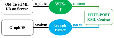
❊❞✐tPr♦♣❡rt②❖♣❡r❛t✐♦♥objects can be transformed to corre-sponding WFS transactions using their respective stored informa-tion. The same applies for❊❞✐t◆♦❞❡❖♣❡r❛t✐♦♥with the only exception of■♥s❡rt◆♦❞❡❖♣❡r❛t✐♦♥, which requires a payload (or content) encoded in XML (Vretanos, 2014). XML contents of affected entities can be retrieved by using a Graph-to-CityGML parser, which basically is the reverse of the mapping process introduced in Section 3 as described in Figure 10. For a more comprehensive look at the specifications of WFS requests and responses, please refer to (Vretanos, 2014) and (Nguyen, 2017).
WFS-T
HTTP-POST XML Content
Graph Parser
update content
parse
content Old CityGML
DB on Server
GraphDB
7. EXAMPLE
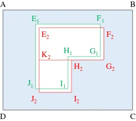
In this section, two syntactically different but geometrically equiv-alent polygons shall be compared (Figure 11). Both polygons contain one exterior▲✐♥❡❛r❘✐♥❣ABCD. However, the hole in the first polygon is represented by an interior▲✐♥❡❛r❘✐♥❣
E1F1G1H1I1J1, while that of the second polygon is composed of two adjacent interiors, namelyE2F2G2K2andK2H2I2J2. Each ▲✐♥❡❛r❘✐♥❣can be defined by either a❣♠❧✿♣♦s▲✐stor a set of ❣♠❧✿♣♦sor❣♠❧✿♣♦✐♥tPr♦♣❡rt②elements. The declared order and number of vertices (e.g. E2F2G2K2 or G2H2K2E2F2) are insignificant. In addition, distance deviations within allowed error tolerances are detected between the interiors of both polygons.
A B
C D
E1
E2
F1
F2
G1
G2 H1
H2
I1
I2 J1
J2 K2
Figure 11. An example of two geometrically matched polygons (considering error tolerances) that are syntactically different.
The application returns a list of edit operations, which can be executed to make the first polygon identical to the second one. However, all of these operations are flagged as optional indicat-ing that both polygons are correctly matched considerindicat-ing their equivalent geometry and error tolerances among coordinates.
8. APPLICATION RESULTS
8.1 Test Setup
All experiments in this research are performed on a dedicated server-class machine running SUSE Linux Enterprise Server 12 SP1 (64 bit) and equipped with Intel®Xeon®CPU E5-2667 v3 @3.20GHz (16 CPUs + Hyper-threading), a Solid-state Drive Array (SSD) connected via PCIe as well as 1 TB of main memory.
The tests use an input dataset of the 3D city model of Berlin. The dataset is encoded in CityGML v2.0.0, contains LOD2 information
of539,182buildings and occupies15.5GB in physical storage.1
The new dataset contains changes added manually to the old one.
8.2 Test Configurations
Both the testing system and Neo4j share the same Java Virtual Machine (JVM), which is provided with an initial and maximum heap space of30GB. The concurrent garbage collector●✶●❈is employed. The application configurations for the mapping and matching process are empirically determined to ensure a stable testing environment and optimum throughput. Namely, by de-fault (unless specified otherwise), the following configurations are applied: multi-threading with 1 producer and 15 consumers, splitting CityGML elements per collection member (top-level fea-ture), indexing using hash maps stored in memory while mapping, matching buildings using an R-tree withM=10, batch size of 10 buildings and 5000 operations per database transaction.
1The CityGML datasets of Berlin are available under❤tt♣✿✴✴✇✇✇✳
❜✉s✐♥❡ss❧♦❝❛t✐♦♥❝❡♥t❡r✳❞❡✴❡♥✴❞♦✇♥❧♦❛❞♣♦rt❛❧.
8.3 Experiment Results
8.3.1 Statistics of Mapped Graph Database A total number
of321,142,046nodes representing1,078,364buildings, including
e.g. 12,928,580polygons and5,864,792boundary surfaces are
created after the mapping process of two 3D city models of Berlin is complete. The graph database allocates126GB of disk storage in total (excluding test and indexed data).
8.3.2 Multi-threading Performance The multi-threading im-plementation of the mapping and matching process employs the well-known producer-consumer design pattern. The differences in performance between some combinations of numbers of produc-ers and consumproduc-ers are shown in Figure 12. The results show that the matching process generally benefits more from the number of concurrent threads than mapping. However, diminishing returns are observed where the total number of producers and consumers exceeds that of the testing system’s physical CPU cores.
0 50 100 150
1P1C
1P7C
1P15C
1P31C
146.1
26.4
15.7
13.5
107.5
58.8
63.7
82.6
minutes Runtime of Mapping
Runtime of Matching
Figure 12. Differences in multi-threading performance. P and C denote the number of producers and consumers respectively.
8.3.3 Indexing Performance while Resolving XLinks The impact of storing indices on disk (using Neo4j legacy indices) and in memory (using self-developed internal hash maps) on perfor-mance is shown in Figure 13. Indexing using internal hash maps results in a much better overall performance but requires a large amount of memory. On the other hand, Neo4j indices stored on disk do not require as much main memory but are significantly slower due to expensive disk read and write operations.
0 50 100 150 200 250 300
Own indexing Neo4j indexing
15.7 13.6
9.9 9.7
9.2 53.3
44.1
271.2
minutes Runtime of Mapping (Creating feature graphs) Runtime of Mapping (Resolving XLinks)
Runtime of Mapping (Computing bounding shapes) Runtime of Matching
9. CONCLUSION AND FUTURE WORK
Overall, the mapping process developed in this research is capable of handling arbitrarily large-sized CityGML documents given a reasonable amount of memory and storage allocation. It facili-tates the seamless interaction between unmarshalling CityGML elements to Java objects with the help of citygml4j and mapping Java objects to graph entities using Neo4j’s Java Core API.
The matching process can disambiguate the common syntactic ambiguities existing in GML between XLink and in-line object declarations. All changes made to the old city model in Section 8 were identified correctly. In addition, although LOD2 data were used in the test scenarios, changes in other LODs can also be detected. Moreover, geometric objects such as points, line seg-ments, polygons, surfaces, etc. can be matched correctly even with altered identifiers. Furthermore, buildings can be organized in a grid layout or an R-tree based on their spatial allocations. These strategies offer a noticeable boost in overall performance.
Found deviations are attached to their respective sources in the graph database and can be transformed to WFS requests comply-ing with the official OGC standards. In case of complex XML properties, such as CityGML generic attributes and external refer-ences, although the update procedures can be formally represented by graphs, the ordinary WFS is not expressive enough in such scenarios. Thus, vendor-specific extensions allowed by the WFS standard, such as defined by the virtualcityWFS, can be employed.
Some improvements and extensions are possible in the near fu-ture. For instance, momentarily, only the modules❇✉✐❧❞✐♥❣and ❆♣♣❡❛r❛♥❝❡are implemented. Other CityGML modules, like ❈✐t②❋✉r♥✐t✉r❡,❚r❛♥s♣♦rt❛t✐♦♥,❇r✐❞❣❡,❚✉♥♥❡❧, etc. can be included in the future. Moreover, it is previously assumed that both CityGML input documents are provided in the same spatial reference system, which is not always the case in practice. Therefore, one future task is to integrate the transformation be-tween different spatial reference systems in the implementation. In addition, more thorough tests are required to evaluate applica-tion outputs against all different types of geometrical deviaapplica-tions. Finally, the methods and algorithms proposed in this research can be extended and applied to enable a version control system for collaborative work in modelling and storing digital 3D city models in the future (Chaturvedi et al., 2015).
References
[1] M. Bakillah, Y. Bédard, M. A. Mostafavi, and J. Brodeur. “SIM-NET: A View-Based Semantic Similarity Model for Ad Hoc Networks of Geospatial Databases.” In:T. GIS
13.5-6 (2009).
[2] M. d. Berg, O. Cheong, M. v. Kreveld, and M. Overmars.
Computational Geometry: Algorithms and Applications.
3rd ed. Springer, 2008.
[3] T. Bray, J. Paoli, C. M. Sperberg-McQueen, E. Maler, and F. Yergeau.Extensible Markup Language (XML) 1.0. Fifth edition. W3C. Nov. 2008.
[4] K. Chaturvedi, C. S. Smyth, G. Gesquière, T. Kutzner, and T. H. Kolbe. “Managing versions and history within seman-tic 3D city models for the next generation of CityGML.”
In:Selected papers from the 3D GeoInfo 2015 Conference.
Ed. by A. A. Rahman. Springer, 2015.
[5] S. Cox, P. Daisey, R. Lake, C. Portele, and A. White-side.OpenGIS Geography Markup Language (GML)
Im-plementation Specification. Specification OGC 03-105r1.
Version 3.1.1. Open Geospatial Consortium, 2004.
[6] S. DeRose, E. Maler, D. Orchard, and N. Walsh.XML
Linking Language (XLink) Version 1.1. W3C. May 2010.
[7] M. J. Egenhofer and R. D. Franzosa. “Point-set topological spatial relations.” In:International Journal of
Geographi-cal Information Systems5.2 (1991).
[8] M. J. Egenhofer and J. Herring.Categorizing binary topo-logical relations between regions, lines, and points in
ge-ographic databases. Technical report. Department of
Sur-veying Engineering, University of Maine, 1991.
[9] G. Gröger.Modeling Guide for 3D Objects - Part 1:
Ba-sics (Rules for Validating GML Geometries in CityGML).
❤tt♣✿✴✴❡♥✳✇✐❦✐✳q✉❛❧✐t②✳s✐❣✸❞✳♦r❣✴✐♥❞❡①✳♣❤♣✴ ▼♦❞❡❧✐♥❣. Version 0.6.0. Accessed: 20170301. SIG3D -Special Interest Group 3D, Dec. 15, 2010.
[10] G. Gröger, T. H. Kolbe, C. Nagel, and K.-H. Häfele.
OpenGIS(R) City Geography Markup Language (CityGML)
Encoding Standard. Version: 2.0.0. OGC. Apr. 2012.
[11] A. Guttman. “R-trees: A Dynamic Index Structure for Spa-tial Searching.” In:Proceedings of the 1984 ACM SIGMOD
International Conference on Management of Data.
SIG-MOD ’84. ACM, 1984.
[12] J. W. Hunt and M. D. McIlroy.An Algorithm for Differen-tial File Comparison. Computing Science Technical Report. Bell Laboratories, June 1976.
[13] C. Nagel. citygml4j - The Open Source Java API for
CityGML. ❤tt♣s ✿ ✴ ✴ ❣✐t❤✉❜ ✳ ❝♦♠ ✴ ❝✐t②❣♠❧✹❥ ✴
❝✐t②❣♠❧✹❥. Version 2.4.3. Accessed: 2017-03-01. 2017. [14] G. Navratil, R. Bulbul, and A. U. Frank. “Maintainable 3D
Models of Cities.” In:Proceedings of the 15 International Conference on Urban Planning, Regional Development
and Information Society. Real CORP, 2010.
[15] S. H. Nguyen. “Spatio-semantic Comparison of 3D City Models in CityGML using a Graph Database.” Master’s thesis. Department of Informatics, Technical University of Munich, May 2017.
[16] A. Olteanu, S. Mustière, and A. Ruas. “Matching imperfect spatial data.” In:Caetano, M., Painho, M.(Es.), Proceed-ings of 7th International Symposium on Spatial Accuracy Assessment in Natural Resources and Environmental Sci-ences. Lisbon. 2006.
[17] Oracle Corporation. Java Architecture for XML
Bind-ing (JAXB). ❤tt♣ ✿ ✴ ✴ ❞♦❝s ✳ ♦r❛❝❧❡ ✳ ❝♦♠ ✴ ❥❛✈❛s❡ ✴
t✉t♦r✐❛❧✴❥❛①❜✴✐♥tr♦✴❛r❝❤✳❤t♠❧. Tutorial. Accessed: 2017-03-01. 2015.
[18] R. Redweik and T. Becker. “Change Detection in CityGML Documents.” In:3D Geoinformation Science: The Selected
Papers of the 3D GeoInfo 2014. Springer, 2015.
[19] H. Tveite. “An accuracy assessment method for geograph-ical line data sets based on buffering.” In:International journal of geographical information science13.1 (1999).
[20] P. A. Vretanos.OGC®Web Feature Service 2.0 Interface
Standard. OGC®Standard 09-025r2. Version 2.0.2. Open
Geospatial Consortium, July 2014.
[21] Y. Wang, D. J. DeWitt, and J. Y. Cai. “X-Diff: an effec-tive change detection algorithm for XML documents.” In: