T
his article describes the design and control of a powered knee and ankle prosthesis for transfemoral amputees. Following a de-scription of the design hardware, a hybrid control approach that pro-vides coordination for level walking is described. The hybrid control ap-proach combines a piecewise-passive impedance-based component during the stance phase of gait with a high-impedance trajectory-tracking com-ponent during the terminal stance and swing. To validate the design, the controller was implemented on the powered prosthesis prototype, and its ability to provide level walking func-tionality was evaluated on three transfemoral amputee subjects. The data presented from these experi-mental trials indicate that the pros-t h e s i s a n d c o npros-t r o l ap p r o a c h reproduce knee and ankle joint kine-matic and kinetic features that are highly representative of correspond-ing healthy joint biomechanics.Emergence of Powered Prostheses
Lower-limb prostheses have tradition-ally been energetictradition-ally passive devices (i.e., they can store or dissipate power but cannot produce net power). Amputees who utilize passive limbs generally walk more slowly, expend significantly more energy during ambulation, are more limited in the types of terrain they can traverse and
Digital Object Identifier 10.1109/MRA.2014.2360303 Date of publication: 13 November 2014
A Robotic Leg Prosthesis
A Robotic Leg Prosthesis
By Brian E. Lawson, Jason E. Mitchell, Don Truex, Amanda Shultz, Elissa Ledoux, and Michael Goldfarb
types of activities they can perform, and fall frequently rela-tive to healthy counterparts [1]–[9]. The intent of a prosthe-sis is to replace the biomechanical functionality of the healthy limb. The joints of the healthy limb provide a variety of biomechanical behaviors that vary considerably within and between activities and that are, in general, characterized by power dissipation, storage, and generation. As such, it is reasonable to assume that endowing a prosthesis with power and, by extension, with the ability to emulate the variegated behaviors exhibited by the healthy limb, would alleviate some of the previously cited deficiencies in mobility and stability.
Although investigations of powered prostheses started sev-eral decades ago (e.g., [10] and [11]), the vast majority of rele-vant research has occurred within the past decade, due presumably to recent enabling improvements in constituent component technology, such as the increased power density of brushless dc motors, the increased energy and power density of lithium-polymer and lithium-ion batteries, and the en-hanced functional capability of low-power microcontrollers and integrated-circuit-based inertial measurement units (IMUs). The publications describing powered prosthetic sys-tems to date can be grossly classified as those describing the development of powered ankle prostheses (and corresponding control systems) (e.g., [12]–[21]), which have been directed at limb replacement for people with transtibial amputation, and those describing the development of powered knee prostheses (and corresponding control systems) (e.g., [22]–[25]), which have been directed at limb replacement for people with trans-femoral amputation. The design and control approaches asso-ciated with these powered prosthesis systems vary considerably, and the interested reader is referred to the cited articles for details regarding the device design and correspond-ing control approaches for each.
Over the past decade, a powered knee and ankle prosthe-sis system has been developed, which is described in this article. Unlike the previously mentioned research efforts, which describe single-joint-powered prosthesis systems, the prosthesis system described here incorporates and coordi-nates the actions of both a powered knee and ankle joint, with the intention of better replicating the biomechanical functionality of the healthy limb for people with transfemo-ral amputations. This article is intended to present and sum-marize the significant design and control aspects of this pros-thesis system, which currently exists in its third major design generation. Relative to the previously cited published works, and relative to prior publications on related topics (e.g., [26]– [30]), this article presents and describes a new and substan-tially different design of a powered knee and ankle prosthesis (in the “Prosthesis Design” section) that offers a number of desirable features relative to previously published designs.
Prosthesis Design
Design Objectives
As presented in [26] and [30], the nominal torque, speed, and range of motion design objectives for each joint are informed
by the superposition of biomechanical data published for healthy subjects for the basic activities of locomotion, princi-pally walking and stair ascent and descent. As described in those articles, such activities require a nominal range of motion, maximum torque, and peak power of 120°, 75 Nm, and 150 W, respectively, at the knee joint and 65°, 130 Nm, and 250 W, respectively, at the ankle joint.
The design shown here incorporates several objectives beyond those associated with the electric design previously described in [26].
● It is intended to incorporate mechanically separable knee
and ankle joints that are connected via a pyramid connec-tor and pylon interface, which enables compatibility with the mechanical interfacing, height adjustment, and align-ment norms of the prosthetics industry.
● To fit a larger population of individuals, the prosthesis was
designed to accommodate a lower minimum-build height relative to the previously presented design.
● For both cosmetic and protective reasons, each joint of the
prosthesis was designed with a fully enclosed actuator and transmission.
● In an effort to increase the operational lifetime of the
prosthesis, the present device was designed such that no electrical wires cross
either the knee or ankle joint (i.e., all instances of flexing wires were eliminated).
● The previously
pre-sented design incorpo-rated instrumentation (i.e., strain gages) on the foot. To more easily accommodate the wide variety of foot sizes used in a lower-limb prosthesis in addition
to eliminating flexing wires (across the ankle joint), the present device was designed with a noninstrumented foot.
● In place of load information from the foot, load
informa-tion in the design described here is provided by a load cell located in the shank.
Attaining all of these objectives necessitated a complete rede-sign relative to that presented in [26] such that the current device is different in essentially every component, as described below.
Actuation and Structure
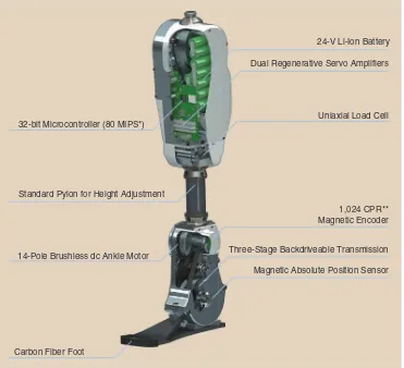
A rendering of the powered prosthesis, with some sections cut away to show design components, is shown in Figure 1. In addition, a summary of key design characteristics is included in Table 1. As shown in Figure 1, the prosthesis consists of a powered knee unit and a powered ankle unit separated by a standard prosthetic pylon, allowing alignment adjustments between the knee and ankle axes as well as adjustability of the shank length. As shown in the figure, the knee unit includes a
The control approach
requires software
emulation of stiffness
and damping at each joint
via feedback-controlled
battery and embedded system that powers and controls both joints. The knee unit additionally incorporates a load cell, which measures the ground reaction force along the shank. The knee and ankle units are electrically connected by a flexi-ble wire tether to accommodate height adjustability.
The control approach described subsequently requires that each joint of the prosthesis be capable of utilizing feedback
control to provide soft-ware emulation of a range of stiffness and damping behaviors. Such an emulation requires four-quadrant control of power at each actuated joint and, thus, requires a torque-controllable and backdrivable joint. To provide this design ob-jective, both the knee and ankle units were de-signed incorporating the combination of a brush-less dc motor and a three-stage belt/chain speed reduction trans-mission. In particular, the knee incorporates a 30 mm Maxon EC-4pole brushless dc motor, which drives the knee joint through a 176:1 speed reduction, the combination of which is capable of generating a maximum active torque of approximately 85 Nm through its actuated range of motion of 120° (5° hyperextension and 115° of flexion). The ankle joint incorporates a 60-mm Maxon 14 pole brushless dc motor, which drives the ankle joint through a 115:1 speed reduction, the combination of which is capable of generating a maximum active torque of approxi-mately 110 Nm through its actuated range of motion of 70° (25° dorsiflexion and 45° plantar flexion). The actuator output at the ankle joint is supplemented by a carbon-fiber leaf spring incorporated into the foot, which is characterized by a stiffness of approximately 6 Nm/° and engages at approximately 0° in the ankle range of motion. The spring biases the output capa-bilities of the ankle toward plantar flexion, which is consistent with the biomechanical characteristics of the ankle during lo-comotion [31]. At typical ankle angles during late stance, the spring provides around 60 Nm of supplemental torque. Note that the spring is initially calibrated and subsequently canceled within the low-level control system (e.g., a command of zero torque from the low-level controller will result in a freely mov-ing joint). In this manner, the only substantive effect of the parallel ankle spring is to shift the maximum torque and power output capabilities of the joint to better align with the asymmetric output characteristics of the healthy ankle.
The structural components of the knee and ankle units are machined from 7075 aluminum alloy. The knee and ankle structures are designed to accommodate users of up to 115-kg 32-bit Microcontroller (80 MIPS*)
24-V Li-Ion Battery
Dual Regenerative Servo Amplifiers
Uniaxial Load Cell
1,024 CPR** Magnetic Encoder
Three-Stage Backdriveable Transmission
Magnetic Absolute Position Sensor Standard Pylon for Height Adjustment
14-Pole Brushless dc Ankle Motor
Carbon Fiber Foot
Figure 1. A rendering of the computer-aided design model of the powered prosthesis. *MIPS: mega-instruction cycles per second.**CPR: counts per revolution.
Table 1. The mechanical and electrical characteristics of the powered prosthesis.
Characteristic Value
Maximum knee torque 85 Nm
Maximum ankle torque 110 Nm (from motor)
Knee range of motion* -5° to 115°
Ankle range of motion† -45° to 25°
Battery capacity 125 W·h
Maximum battery current 30 A
Maximum motor current 18 A
Nominal mass‡ 5 kg
*Positive in flexion †Positive in dorsiflexion
body mass in addition to the internal loads imposed by the actuators, with a minimum safety factor of two against struc-tural failure. Given the respective sizes of the knee and ankle units, the minimum build height of the prosthesis corre-sponds to a measurement between the knee center and ground of 425 mm, which corresponds to a tenth percentile female dimension, as given by [32] (i.e., the prosthesis should fit all adult males and 90% of the adult female population). As configured for a 50th percentile male, the mass of the pros-thesis prototype is approximately 5 kg.
Sensing
In addition to a six-axis IMU in the shank, the prosthesis in-cludes sensing for the knee and ankle angles and angular ve-locities as well as for the axial load in the shank. All sensing is based on contactless sensors to enhance reliability and life-time. The angular positions of the knee and ankle joints are measured by absolute magnetic encoders [pulse width mod-ulation (PWM) output with a resolution of 4,096] located co-axially with the joints, and also by incremental magnetic encoders (1,024 counts per revolution (CPR), counted in quadrature) located coaxially with the motor shafts. Note that although the sensor resolution is the same, the incre-mental encoder provides a measurement resolution relative to the joint approximately two orders of magnitude greater than the absolute encoder since its resolution is effectively multiplied by the transmission ratio of the respective joint (i.e., 176 for the knee or 115 for the ankle). To mitigate drift in the absolute angular position measurement of each joint, position information from the incremental encoder (around the motor) is fused with position information from the abso-lute encoder (around the joint) with first-order complemen-tary filters with -3-dB crossover frequencies of 1 Hz. The
angular velocities of the knee and ankle joints are calculated from the incremental magnetic encoders on the motor shafts using a differentiator with a second-order roll off at 40 Hz. Note that all filters are implemented as discrete-time approx-imations of continuous-time transfer functions at a sampling rate of 500 Hz. The axial load in the prosthetic shank is mea-sured through the previously mentioned load cell, which is situated just distal to the knee unit (shown in Figure 1). The load cell consists of a pair of parallel plates, which are sepa-rated by a helical compression spring with a stiffness of ap-proximately 360 N/mm (2,080 lb/in) and are constrained such that one plate moves in a strictly rectilinear path along the long axis of the shank relative to the other. The motion constraint is provided by a pair of symmetric seven-bar link-ages, each constructed by mirroring two parallelogram four-bar linkages about a common central link. A linear magnetic encoder measures the displacement between the plates (i.e., across the spring) and thus produces a measure of the shank axial load. The measurement range can be variably config-ured, but for the experiments described here, it was set for a maximum axial load of 1,000 N (225 lb). Given the use of a 10-b analog-to-digital converter (ADC), a measurement range of 1,000 N results in a measurement resolution of
approximately 1 N. Note that, at maximum load, the load cell compresses approximately 2.8 mm (0.110 in).
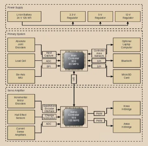
Embedded Electronics
The essential components of the prosthesis electrical system are shown in Figure 2. The prosthesis power supply is a nomi-nal 24-V lithium-ion battery pack, rated at approximately 125 Wh. Since the prosthesis consumes approximately 85 W of electrical power during normal level walking (the average for the three subjects tested for this article), the battery pack is estimated to provide 1.5 h of continuous walking on a full charge, which corresponds to a walking range of approxi-mately 6.75 km at a typical speed of 4.5 km/h. The main pro-cessing element is a 32-b microcontroller from Microchip Technologies (PIC32MX575F512L), which runs the primary control loop at 500 Hz. In this loop, the main controller exe-cutes the joint torque
con-trollers (described in the “Control Approach” sec-tion) in addition to per-forming secondary func-tions such as logging data, communicating with the servo controller, and ser-vicing other peripherals [such as communication with the IMU over the serial peripheral interface (SPI)]. A secondary pro-cessing element (a 16-b digital signal processor from Microchip Technolo-gies, dsPIC33FJ64GS608) receives motor current commands from the main controller at 500 Hz and
uses these references to control the current in the brushless dc motors via a pair of custom regenerative servo-amplifiers, each of which samples the motor current at 150 kHz, runs closed-loop current control at a sample rate of 4.6 kHz (based on a fil-tered version of the sampled motor current), and switches the metal–oxide–semiconductor field‐effect transistor (MOSFET) bridges at a PWM rate of 45 kHz. The current control loop for each motor consists of the combination of a feedforward motor model supplemented with a proportional-integral feed-back loop.
Control Approach
Low-Level Control
As previously mentioned, the control approach requires soft-ware emulation of stiffness and damping at each joint via feedback-controlled actuation. As described in [33]–[35], the capacity of a feedback-controlled system to emulate a range of stiffness and damping behaviors is limited by the extent of open-loop phase lag (i.e., dynamics), sensor quantization,
The prosthesis system
described here incorporates
and coordinates the
actions of both a powered
knee and ankle joint,
with the intention of
better replicating the
biomechanical functionality
sampling delay, and hard nonlinearities (such as Coulomb friction and backlash) within the feedback loop. To minimize the presence of these behaviors in the feedback loop, a con-trol structure is implemented in the prosthesis in which the high frequency content of the position signal for the feed-back loop is closed around the motor, rather than around the motor and transmission combination. This approach enables stable emulation of a wide range of stiffness and damping behaviors at the motor and reflects the resulting (simulated
passive) behaviors to the user and the environment through the dynamics of the mechanical transmission. Such an approach requires a sufficiently transparent transmission rel-ative to the dynamic characteristics of locomotion and spe-cifically requires that the first mode of vibration of the trans-mission be high relative to the frequency content of gait. In addition, the frictional characteristics of the transmission should be small relative to the characteristic levels of torque required for locomotion.
Power Supply
Li-Ion Battery 24 V 125 Wh
Absolute Joint Encoders
Input
Capture Main
Controller 32-b 80 MIPS
Servo Controller
16-b 100 MIPS
Controller Area Network
ADC SPI
SPI
Quadrature Encoder Interface
PWM
PWM Change
Notification
ADC
SPI
SPI Load Cell
Six-Axis IMU
Optional Laptop Computer
Bluetooth
MicroSD Card
Knee H-Bridge
Ankle H-Bridge Incremental
Motor Encoders
Hall Effect Sensors
Current Sense Amplifiers
3.3-V Regulator
5-V Regulator
12-V Regulator
Primary System
Servo Amplifier
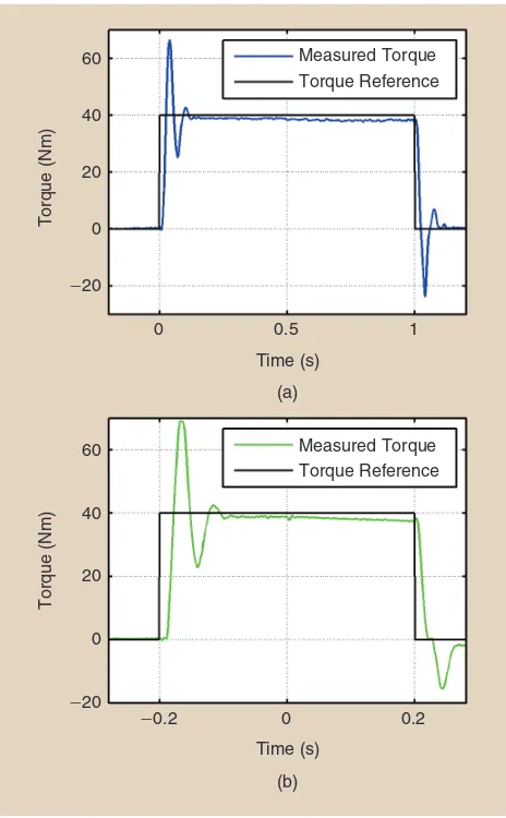
Figure 3 shows the measured open-loop characteristics of the joint transmissions for both the knee and ankle joints. In particular, the plots show the measured joint torque relative to the commanded joint torque for each joint for a commanded step of 40 Nm. The output torque was measured on a bench-top setup using a bidirectional load cell (Transducer Tech-niques Model MLP-100), which was zero-phase-filtered at 30 Hz to reduce analog noise. As shown in the figure, the knee joint transmission dynamics are characterized by a rise time of approximately 100 ms, a damped natural frequency at approximately 15 Hz, and a steady-state torque error of approximately 2.5%. The ankle joint transmission dynamics are characterized by a rise time of approximately 250 ms, a damped natural frequency of 6 Hz, and a steady-state torque error of approximately 2.5%. Since the knee and ankle joint torque data for healthy subjects are characterized by signifi-cant frequencies at or below 1–2 Hz (as given by a fast Fourier transform (FFT) of the data presented in [31]), the transmis-sion dynamics of the knee and ankle joints (with damped nat-ural frequencies of 15 and 6 Hz, respectively) are assumed to essentially preserve the torque dynamics characteristic of walking. As such, both knee and ankle joints are able to pro-vide highly stable stiffness and damping emulation (as a result of excluding the transmission dynamics from the software emulation loop) in addition to accurate torque tracking within the frequencies and magnitudes of joint torques char-acteristic of human locomotion.
Coordination Control
The prosthesis control system consists of a hierarchical state machine, the top layer of which is called the supervisory controller. The states of the supervisory controller are called
activities. An activity is itself a finite-state machine, the states of which are called phases. The supervisory controller gov-erns transitions from one activity to another, while each activity controller dictates transitions from one internal phase to another. There are four activities contained in the supervisory controller. These activities are shown in the state machine depicted in Figure 4. Within any given phase of any given activity, impedance parameters and equilibria are spec-ified for the knee and ankle joints. The impedance control law for each joint within each finite state is given by
( ) ,
k eq b
x= i-i + io (1)
where x is the commanded torque, k is the proportional gain or stiffness, i is the joint angle, ieq is the desired joint
angle equilibrium position, b is the damping coefficient, and io is the joint angular velocity. These stiffness and damping behaviors are emulated via the previously mentioned low-level control structure. Note that the control law does not ex-plicitly track motion or torque but rather emulates the physical relationship (i.e., the impedance) between these two quantities. This approach provides two substantial features. First, joint impedances can be selected that are representative of impedances exhibited by the healthy joint, which
facilitates interaction with the ground and should provide the user a more natural feel relative to a (high-impedance) position controlled joint. Second, the behavior of the pros-thesis within any given phase will be passive, but energy can be introduced into the system by changing the stiffness or equilibrium position of the virtual spring during transitions
Time (s)
Measured Torque Torque Reference
Measured Torque Torque Reference (a)
0
-20 0 20
Torque (Nm)
40 60
-20
0 20
Torque (Nm)
40 60
0.5 1
Time (s)
(b)
-0.2 0 0.2
Figure 3. The experimentally measured response of the (a) knee and (b) ankle joints to a 40-Nm step command in joint torque.
Walking Controller
Standing Controller
Stair Ascent Controller
Stair Descent Controller Time Out
Time Out Time Out
Nonweight-Bearing Anterior
Weight-Bearing Posterior
Nonweight-Bearing Posterior
between phases. Since phase transitions are based on me-chanical cues from the user, the user retains control over the introduction of power into an otherwise passive system. Thus, the control approach provides both a natural feel (due to the selection of joint impedances) and an inherent safety characteristic (since the user has to be engaged to keep the prosthesis moving, and, in the absence of direct excitation or input from the user, the prosthesis defaults to passive
behav-ior). For further details regarding this frame-work, see [36].
Despite the features provided by this piece-wise-passive impedance-based control approach, the approach is some-what parameter-inten-sive since each phase for each joint requires selec-tion of three impedance parameters. As such, for a pi e c e w is e - p ass ive impedance-based con-trol approach for level walking with five phases, the two joints together would require the selection of 30 impedance parameters. To reduce the number of control parameters, a hybrid control approach was implemented for the walking controller. In particular, since the effect of joint impedance is most evident when the prosthesis is in the stance phase of gait (i.e., when the user is interacting with the ground, which is a high-impedance environment)
and less evident when the prosthesis is actively pushing off at the ankle or in swing, a control approach that
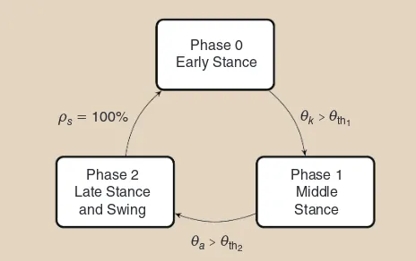
incorpo-rates a piecewise-passive impedance control approach dur-ing early and middle stance but incorporates a trajectory-tracking high-impedance controller during the terminal stance (which is an active segment of the gait cycle) and the swing phase of gait was implemented. The resulting hybrid walking controller consists of three phases, as shown in Fig-ure 5. The first two phases, early and middle stance, are basic impedance states that roughly correspond to the first 40% of the gait cycle. The early stance portion begins at heel strike and ends at peak stance knee flexion, entering middle stance. Middle stance continues until an ankle angle threshold is reached, at which point the prosthesis initiates a step with a powered pushoff.
In the third phase, instead of executing a series of piece-wise passive phases, each of which would entail impedance parameter selection, the hybrid controller executes a trajec-tory at a relatively high impedance, where the trajectrajec-tory for each joint follows a spline defined by a set of reference points interpolated from healthy walking data at different walking speeds. To achieve a variable cadence, the interpolation is based on the length of time spent in the preceding stance phase, as determined by a timer that increments while the load signal is above a given threshold. Once the trajectory has finished, the prosthesis automatically reverts to the first phase, early stance, in anticipation of a heel strike. To provide the energetic role of pushoff in late stance, a feedforward torque command is superimposed at the onset of the trajectory phase. The torque command is a single period of a unity-off-set cosine wave, which provides a smooth and computation-ally simple torque pulse that is scalable in both width (time) and height (magnitude). This form of torque input provides an intuitive mechanism for the tuning of the amount of push delivered to (and perceived by) the user. Note that the strength of the powered pushoff largely determines the net amount of energy delivered to the user over the stride.
Experimental Implementation and Biomechanical Results
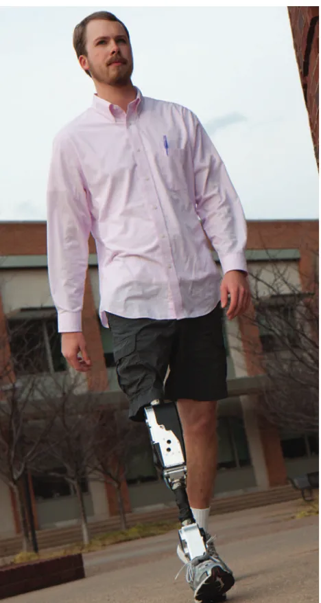
The efficacy of the powered prosthesis design and control approach was assessed in experiments with three transfemo-ral amputee subjects. The ability of the powered prosthesis and controller to provide level walking functionality was assessed by characterizing the knee and ankle joint biome-chanics (e.g., joint angles, torques, and powers) during over-ground walking, and comparing these to the biomechanical behavior of the knee and ankle joints in the healthy limb.
Biomechanical Assessment
Three subjects were recruited through local prosthetists for the assessment. The subjects’ anthropomorphic data, along with data concerning the configuration of the prosthesis, are given in Table 2. Approval to perform these assessments was granted by the Vanderbilt Institutional Review Board, and informed consent was obtained for each subject prior to each assessment. The subjects additionally gave permission for the publication of the photographs and video. Figure 6 shows a Phase 0
Figure 5. The walking state machine for the powered prosthesis. Phases 0 and 1 emulate the virtual impedance equation described by (1), with parameters tuned for each subject and listed in Table 2. Phase 2 executes a trajectory as described in the text and automatically reverts to phase 0 upon completion of the trajectory (when ts is equal to 100%, which denotes the
percentage of the stride). The transition from phase 0 to phase 1 is governed by the listed condition, where ik is the knee angle
and ith1 is a predetermined threshold. The transition from phase
1 to phase 2 is governed by the listed condition, where ia is the
ankle angle and ith2 is a predetermined threshold.
The prosthesis was
designed to emulate a
generalizable mechanical
behavior and also to
modify this behavior in real
time, as governed by the
photograph of one of the subjects walking with the powered prosthesis.
The prosthesis was fit to each subject, and the controller parameters were manu-ally tuned. The primary controller parame-ters requiring tuning are the impedance parameters, the pushoff trigger angle, and the pushoff strength (Table 3). The imped-ance parameters were tuned, starting with a set of nominal parameters obtained from healthy subject data [30] to achieve subject comfort and sense of synergy with the pros-thesis and to achieve a biomechanical movement in the stance phase representa-tive of healthy gait (e.g., the appropriate stance knee flexion). The pushoff trigger angle and strength were adjusted to provide a powered pushoff that was comfortable to the user. A summary of
the control parameters used for each subject is given in Table 3. It is nota-ble that not all the imped-ance parameters needed to be adjusted between sub-jects to obtain a comfort-able gait. The process of parameter tuning is analo-gous to that undertaken by a prosthetist and patient
Table 3. The level walking parameters for the three test subjects.
Subject A Subject B Subject C Knee Ankle Knee Ankle Knee Ankle
Early stance
Nm/
k^ ch 4.5 5 3 5 3.5 2.5
Nm s/
b^ $ ch 0.1 0.2 0.1 0.2 0.1 0.2
( ) eq
i c 10 0 10 0 12 0
Middle stance
Nm/
k^ ch 4 4 4 4.5 4 4
Nm s/
b^ $ ch 0.1 0.2 0.1 0.2 0.1 0.2
( ) eq
i c 10 0 10 0 12 -3
Pushoff
angle 10° 8° 7°
Pushoff strength/ duration*
160 Nm/
300 ms 120 Nm/ 250 ms 200 Nm/ 250 ms
Note: The highlighted parameters were consistent across all three subjects.
*Pushoff strength/duration refers to the peak value and period of the unity-offset cosine torque pulse command that is superimposed with the trajectory controller and is a tunable parameter for the system. This value is not the net torque experienced by the user during pushoff. Figure 6. A subject walking with the powered prosthesis.
Table 2. The subject data and prosthesis configuration.
Subject A Subject B Subject C
Height (m) 1.93 1.83 1.83
Weight (kg) 79 95 86
Age (years) 25 24 46
Cause of amputation Trauma Trauma Cancer
Years postindependent ambulation 7 3 2
Amputation side Right Left Left
Prosthesis configured weight (kg)* 5.09 5.04 5.05
Prosthesis configured height (cm)† 54 51.9 50.5
Prosthesis foot size (cm) 28 28 28
*Excluding foot shell and sneaker
†As measured from the sole plate to the knee center
The process
of parameter tuning
is analogous to that
undertaken by a
when a passive prosthesis is mechanically aligned and adjusted for gait.
Biomechanical Data
Once tuned, each subject walked over the ground on the prosthesis at a self-selected speed. Figures 7–9 show the average biomechanical data from the knee and ankle joints for each of the three subjects, averaged over 12 con-secutive strides. A video is included with the
supplemen-tal material that shows walking corresponding to the data (for Subject A) shown in Figures 7–9. The video is intended to provide a qualitative sense of the data pre-sented here in addition to a sense of the extent to which the prosthesis movement is coordinated with the move-ment of the user (which is not explicitly represented in the data shown in Figures 7–9).
Note that the data shown in these figures were computed in postprocessing using sensor data from the prosthesis. The joint angles (shown in Figure 7) were measured with the absolute and incremental encoders at each joint. The joint torques experienced by the user (shown in Figure 8) were computed using a model of the passive characteristics of the motor, transmission (i.e., inertia and friction), and, in the Time (% Stride)
Normal Walking
(a) 0
0 20 40
Knee Angle (°)
10
0
-10
-20
Ankle Angle (°)
60 80
20 40 60 80 100
Time (% Stride) Healthy
Subject A Subject B Subject C
(b)
0 20 40 60 80 100
Figure 7. The (a) knee and (b) ankle kinematics for three amputee subjects using the powered prosthesis. For the knee joint, 0° corresponds to full knee extension, and flexion is positive. For the ankle joint, positive angles represent dorsiflexion and negative angles represent plantar flexion. The dots represent the average state transitions for each subject (from phase 0 to phase 1 and from phase 1 to phase 2). The crosses represent toe-off, as measured by the load cell. The largest standard deviations for each subject at the knee were 6.95°, 6.85°, 4.27° at 86, 84, and 85% of stride for subjects A, B, and C, respectively. The largest standard deviations for each subject at the ankle were 4.44°, 2.68°, and 1.88° at 57, 58, and 71% of stride for subjects A, B, and C, respectively.
Time (% Stride) Normal Walking
(a) 0
-1.5
-1
-0.5
Knee Torque (Nm/kg)
0.5
0
-0.5
-1.5
-1
-2
Ankle Torque (Nm/kg)
0.5
0 1
20 40 60 80 100
Time (% Stride) Healthy
Subject A Subject B Subject C
(b)
0 20 40 60 80 100
case of the ankle joint, the parallel spring. The following models were used for the ankle and knee joints:
,
where the subscripts a and k represent each parameter or state for the ankle and knee, respectively, Jx is the rotational
inertia for the joint at the output, bx is the viscous damping
coefficient, cx represents the Coulomb friction, and ka and i0
are the spring constant and engagement angle, respectively, for the parallel spring at the ankle. All parameters, which are listed in Table 4, were either
ex-perimentally measured or estimated based on data sheet information or sys-tem identification ap-proaches. The velocity signal used in the torque model was numerically computed from the posi-tion signal instead of using the real-time velocity sig-nal to avoid phase lag from the second-order roll off. The final computed torque was zero-phase
fil-tered with an FFT removing frequencies above 20 Hz for the knee and 10 Hz for the ankle (note that these cutoffs are higher than the respective output torque bandwidths measured ex-perimentally in the “Control Approach” section). The joint powers (shown in Figure 9) were calculated as the product of the joint torques and velocities computed in post processing. Finally, note that stride data were parsed based on load-cell data and, in accordance with standard methods, plotted as a function of stride percentage. In all cases, the data are plotted along with data characterizing plus and minus one standard deviation around the corresponding mean behavior of the knee and ankle joints for healthy subjects measured during level walking at a self-selected speed, as provided by [31].
Figure 7 shows the averaged knee and ankle joint angles for each subject exhibited by the prosthesis during walking. For all subjects, the prosthesis provides knee and ankle joint kinemat-ics with the essential characteristkinemat-ics of healthy joint behavior. In particular, as in healthy walking, the knee joint exhibits stance knee flexion between 0 and 30% of stride, although peak flexion values for the amputee subjects are somewhat less Time (% Stride)
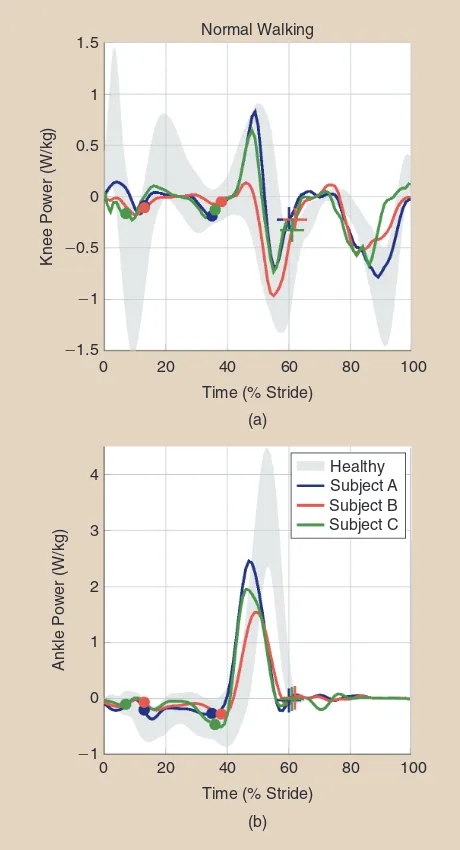
Figure 9. The (a) knee and (b) ankle powers for three amputee subjects using the powered prosthesis. For both joints, positive power is the power delivered by the joint and negative power is the power absorbed by the joint. The dots are the average state transitions for each subject (from phase 0 to phase 1, and from phase 1 to phase 2). The crosses denote toe-off, as measured by the load cell.
For all subjects, the
prosthesis provides knee
and ankle joint kinematics
with the essential
characteristics of healthy
joint behavior.
Table 4. The parameters for the knee and ankle transmission models.
Symbol Parameter Value
ka Ankle spring stiffness* 5.7 Nm/°
0
i Ankle spring engagement angle* 0°
Ja Ankle effective rotor inertia† 1.58 kg·m2
ba Ankle viscous friction* 0.0603 Nm·s/°
ca Ankle Coulomb friction* 1.13 Nm
Jk Knee effective rotor inertia† 0.103 kg·m2
bk Knee viscous friction* 0.0261 Nm·s/°
ck Knee Coulomb friction* 0.802 Nm
than the healthy average. In our experience, amputee subjects tend to prefer slightly less stance knee flexion, perhaps due to the compliance of the socket interface and/or the lack of pro-prioception in the limb.
All subjects’ ankle behaviors also closely match those of healthy subjects. Most notable is the significant plantar flex-ion of the ankle joint around 60% of stride. During this period, the ankle joint is delivering net positive power, which is a characteristic unique to an active device. Further-more, the prosthesis actively returns from plantar flexion after toe-off to provide ground clearance at the toe during the swing phase of walking.
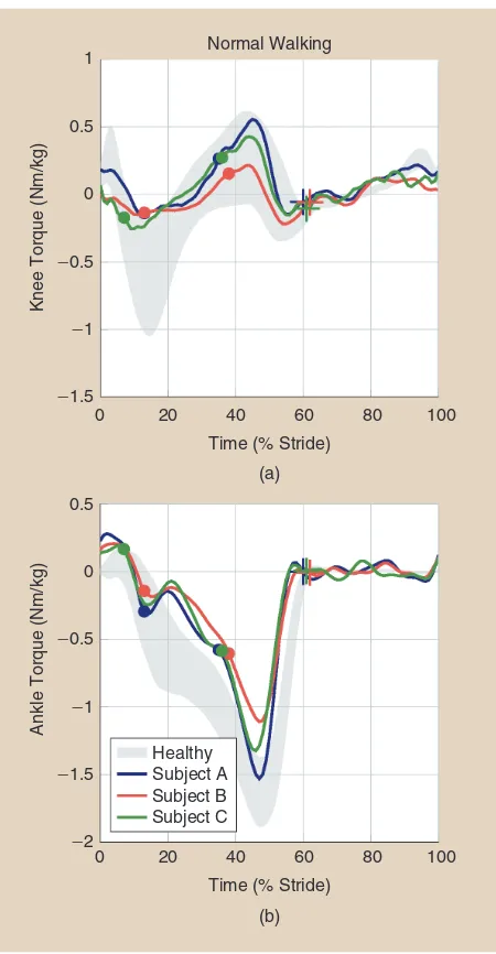
Figure 8 shows the body-mass-normalized knee and ankle joint torques provided by the prosthesis as a function of stride for each subject, also compared with the band of typical healthy subject knee and ankle body-mass-normalized torques. Like the joint kinematics, the joint torques for all subjects are strongly representa-tive of healthy subject data. Regarding the knee torques, the amplitudes for the stance phase reflect the somewhat diminished stance knee flexion relative to healthy subjects. As in the healthy subject data, during the beginning of powered pushoff (approxi-mately 45% of stride), the powered prosthesis provides for each subject a flexive torque to counteract the hyperextensive torque supplied by the ground reaction force.
At the ankle, the prosthesis provides an initial dorsiflexive torque immediately following heel strike, followed by a period of increasing plantar-flexive torque during the stance phase of walking. As in the healthy subject data, the ankle torque increases throughout the stance and peaks during the pow-ered pushoff period between 40 and 60% of stride. Once the toe is off the ground, the external forces on the ankle are small due to the foot’s low moment of inertia and little external torque is present during this period.
Body-mass-normalized knee and ankle joint powers for each subject are shown in Figure 9. As seen in the joint power data, power characterizing the knee and ankle joints falls largely within the healthy subject norms. Regarding the knee joint, power associated with stance knee flexion during early to middle stance is diminished, corresponding to the reduced stance knee flexion seen in these subjects. However, the knee joint power during late stance and swing is quite representa-tive of healthy knee joint power data.
As in the knee joint, the power associated with the ankle joint is also representative of healthy norms. In particular, for each subject, the ankle primarily absorbs power during the early and middle phases of stance and subsequently generates a pulse of
power between approximately 40 and 60% of the stride cycle in accordance with the powered pushoff phase of walking. The net energy delivered by the ankle for each subject was 14.4, 9.5, and 13.7 J/stride for subjects A, B, and C, respectively. Note that the peak power associated with this pushoff is on the low side of the healthy mean; most likely a result of torque and power limita-tions of the hardware. Nonetheless, these data are still in charac-ter with the biomechanical behavior of the healthy joint.
Conclusions
This article describes the design and control of a powered knee and ankle prosthesis for transfemoral amputees. The prosthesis was designed to emulate a generalizable mechani-cal behavior and also to modify this behavior in real time, as governed by the prosthesis controller. The resulting system combines passive impedance-type behaviors at the respective joints during most of the stance phase of gait and relatively high-impedance trajectory control during the swing phase of gait, the combination of which provides coordinated interac-tion with the user and minimal controller parameterizainterac-tion.
The powered prosthesis was demonstrated on three trans-femoral amputee subjects and was shown in all cases to pro-vide knee and ankle joint biomechanical behaviors that are highly representative of healthy joint biomechanics during walking. Finally, although only level walking was described and demonstrated, one of the most unique and compelling attributes of a powered prosthesis, such as the one presented here, is its ability to adapt its behavior to a variety of activities and terrain types and, thus, provide the user appropriate bio-mechanical behaviors across a wide variety of activities. Accordingly, fulfilling the potential of powered prostheses will require the continuing development of coordination control-lers for multiple types of activities in addition to algorithmic structures that recognize when a user intends to transition from one activity to another.
References
[1] J. J. Genin, G. J. Bastien, B. Franck, C. Detrembleur, and P. A. Willems, “Effect of speed on the energy cost of walking in unilateral traumatic lower limb amputees,” Eur. J. Appl. Physiol., vol. 103, no. 6, pp. 655–663, 2008. [2] R. L. Waters, J. Perry, D. Antonelli, and H. Hislop, “Energy cost of walking of amputees: The influence of level of amputation,” J. Bone Joint Surg. Amer., vol. 58, no. 1, pp. 42–46, 1976.
[3] T. Schmalz, S. Blumentritt, and R. Jarasch, “Energy expenditure and bio-mechanical characteristics of lower limb amputee gait: The influence of pros-thetic alignment and different prospros-thetic components,” Gait Posture, vol. 16, no. 3, pp. 255–263, 2002.
[4] S. M. Jaegers, J. H. Arendzen, and H. J. de Jongh, “Prosthetic gait of unilat-eral transfemoral amputees: A kinematic study,” Arch. Phys. Med. Rehab., vol. 76, no. 8, pp. 736–743, 1995.
[5] M. Schmid, G. Beltrami, D. Zambarbieri, and G. Verni, “Centre of pressure displacements in trans-femoral amputees during gait,” Gait Posture, vol. 21, no. 3, pp. 255–262, 2005.
[6] R. E. Seroussi, A. Gitter, J. M. Czerniecki, and K. Weaver, “Mechanical work adaptations of above-knee amputee ambulation,” Arch. Phys. Med. Rehab., vol. 77, no. 11, pp. 1209–1214, 1996.
The hybrid control
approach combines
a piecewise-passive
impedance-based
component during the
[7] A. H. Vrieling, H. G. van Keeken, T. Schoppen, E. Otten, J. P. Halbertsma, A. L. Hof, and K. Postema, “Uphill and downhill walking in unilateral lower limb amputees,” Gait Posture, vol. 28, no. 2, pp. 235–242, 2008.
[8] W. C. Miller, A. B. Deathe, M. Speechley, and J. Koval, “The influence of falling, fear of falling, and balance confidence on prosthetic mobility and social activity among individuals with a lower extremity amputation,” Arch. Phys. Med. Rehab., vol. 82, no. 9, pp. 1238–1244, 2001.
[9] W. C. Miller, M. Speechley, and B. Deathe, “The prevalence and risk factors of falling and fear of falling among lower extremity amputees,” Arch. Phys. Med. Rehab., vol. 82, no. 8, pp. 1031–1037, 2001.
[10] R. Tomovic and R. B. McGhee, “A finite state approach to the synthesis of bioengineering control systems,” IEEE Trans. Human Factors Electron., vol. 7, no. 2, pp. 65–69, 1966.
[11] W. C. Flowers, “Use of an amputee-computer interactive facility in above-knee prosthesis research,” in Proc. ACM Annu. Conf., 1974, vol. 1, pp. 335–339. [12] S. Au, M. Berniker, and H. Herr, “Powered ankle-foot prosthesis to assist level-ground and stair-descent gaits,” IEEE Trans. Neural Netw., vol. 21, no. 4, pp. 654–666, 2008.
[13] S. K. Au, J. Weber, and H. Herr, “Powered ankle-foot prosthesis improves walking metabolic economy,” IEEE Trans. Robot., vol. 25, no. 1, pp. 51–66, 2009. [14] M. F. Eilenberg, H. Geyer, and H. Herr, “Control of a powered ankle–foot prosthesis based on a neuromuscular model,” IEEE Trans. Neural Syst. Rehab. Eng., vol. 18, no. 2, pp. 164–173, 2010.
[15] M. A. Holgate, A. Bohler, and T. G. Sugar, “Control algorithms for ankle robots: A reflection on the state-of-the-art and presentation of two novel algo-rithms,” in Proc. IEEE/RASEMBS Conf. Biomedical Robotics Biomechatronics, 2008, pp. 97–102.
[16] J. K. Hitt, T. G. Sugar, M. Holgate, and R. Bellman, “An active foot-ankle prosthesis with biomechanical energy regeneration,” ASME J. Med. Devices, vol. 4, no. 1, p. 011003, Mar. 2010.
[17] B. J. Bergelin, J. O. Mattos, J. G. Wells Jr, and P. A. Voglewede, “Concept through preliminary bench testing of a powered lower limb prosthetic device,”
ASME J. Mech. Robot., vol. 2, no. 4, pp. 41005–41013, 2010.
[18] B. J. Bergelin and P. A. Voglewede, “Design of an active ankle-foot pros-thesis utilizing a four-bar mechanism,” ASME J. Mech. Des., vol. 134, no. 6, p. 061004, 2012.
[19] R. Suzuki, T. Sawada, N. Kobayashi, and E. P. Hofer, “Control method for powered ankle prosthesis via internal model control design,” in Proc. IEEE Int. Conf. Mechatronics Automation, 2011, pp. 237–242.
[20] P. Cherelle, V. Grosu, A. Matthys, B. Vanderborght, and D. Lefeber, “Design and validation of the ankle mimicking prosthetic foot 2.0,” IEEE Trans. Neural Syst. Rehab. Eng., vol. 22, no. 1, pp. 138–148, 2014.
[21] J. M. Caputo and S. H. Collins, “A universal ankle–foot prosthesis emula-tor for human locomotion experiments,” ASME J. Biomech. Eng., vol. 136, no. 3, p. 035002, 2014.
[22] E. C. Martinez-Villalpando and H. Herr, “Agonist-antagonist active knee prosthesis: A preliminary study in level-ground walking,” J. Rehab. Res. Develop., vol. 46, no. 3, pp. 361–373, 2009.
[23] B. G. A. Lambrecht and H. Kazerooni, “Design of a semi-active knee pros-thesis,” in Proc. IEEE Int. Conf. Robotics Automation, 2009, pp. 639–645. [24] C. D. Hoover, G. D. Fulk, and K. B. Fite, “Stair ascent with a powered transfemoral prosthesis under direct myoelectric control,” IEEE/ASME Trans. Mechatron., vol. 18, no. 3, pp. 1191–1200, 2013.
[25] E. J. Rouse, L. M. Mooney, E. C. Martinez-Villalpando, and H. Herr, “Clutchable series-elastic actuator: Design of a robotic knee prosthesis for minimum energy consumption,” in Proc. IEEE Int. Conf. Rehabilitation Robot-ics, 2013, p. 6650383.
[26] F. Sup, H. A. Varol, J. Mitchell, T. J. Withrow, and M. Goldfarb, “Prelimi-nary evaluations of a self-contained anthropomorphic transfemoral prosthe-sis,” IEEE ASME Trans. Mechatron., vol. 14, no. 6, pp. 667–676, 2009. [27] F. Sup, H. A. Varol, and M. Goldfarb, “Upslope walking with a powered knee and ankle prosthesis: Initial results with an amputee subject,” IEEE Trans. Neural Syst. Rehab. Eng., vol. 19, no. 1, pp. 71–78, 2011.
[28] B. Lawson, H. A. Varol, A. Huff, E. Erdemir, and M. Goldfarb, “Control of stair ascent and descent with a powered transfemoral prosthesis,” IEEE Trans. Neural Syst. Rehab. Eng., vol. 21, no. 3, pp. 466–473, 2013.
[29] B. E. Lawson, H. A. Varol, and M. Goldfarb, “Standing stability enhance-ment with an intelligent powered transfemoral prosthesis,” IEEE Trans. Biomed. Eng., vol. 58, no. 9, pp. 2617–2624, 2011.
[30] F. Sup, A. Bohara, and M. Goldfarb, “Design and control of a powered transfemoral prosthesis,” Int. J. Robot. Res., vol. 27, no. 2, pp. 263–273, 2008. [31] D. A. Winter, The Biomechanics and Motor Control of Human Gait: Normal, Elderly and Pathological. Waterloo, ON, Canada: Univ. Waterloo Press, 1991. [32] C. C. Gordon, T. Churchill, C. E. Clauser, B. Bradtmiller, and J. T. McCo-nville, “Anthropometric survey of U.S. Army personnel: Methods and sum-mary statistics 1988,” Fort Belvoir, VA: DTIC Document, 1989.
[33] J. E. Colgate and J. M. Brown, “Factors affecting the Z-width of a haptic display,” in Proc. IEEE Int. Conf. Robotics Automation, 1994, pp. 3205–3210. [34] J. E. Colgate and G. G. Schenkel, “Passivity of a class of sampled-data systems: Application to haptic interfaces,” J. Robot. Syst., vol. 14, no. 1, pp. 37–47, 1997. [35] N. Diolaiti, G. Niemeyer, F. Barbagli, and J. K. Salisbury, “Stability of hap-tic rendering: Discretization, quantization, time delay, and coulomb effects,”
IEEE Trans. Robot., vol. 22, no. 2, pp. 256–268, 2006.
[36] B. Lawson and M. Goldfarb, “Impedance and admittance-based coordina-tion control strategies for robotic lower limb prostheses,” ASME Dyn. Syst. Control, vol. 2, no. 3, pp. 12–17, 2014.
Brian E. Lawson, Vanderbilt University, Nashville, Tennessee, United States. E-mail: [email protected].
Jason E. Mitchell, Vanderbilt University, Nashville, Tennessee, United States. E-mail: [email protected].
Don Truex, Vanderbilt University, Nashville, Tennessee,
United States. E-mail: [email protected].
Amanda Shultz, Vanderbilt University, Nashville, Tennessee, United States. E-mail: [email protected], [email protected].
Elissa Ledoux, Vanderbilt University, Nashville, Tennessee, United States. E-mail: [email protected].