LAPORAN AKHI R RI SET
Program Riset dan I nvoasi KK
I ntegrasi Algoritma Perencanaan dan Kontrol untuk Sistem Robot
Beroda dengan Pendekatan Global dan Lokal
Periset Utama:
Dr. Augie Widyotriatmo, ST, MT
Nama KK/ P/ PP:
I nstrumentasi dan Kontrol
1
I . HALAMAN I DENTI TAS
1. Judul : ”I ntegrasi Algoritma Perencanaan dan
Kontrol untuk Sistem Robot Beroda dengan Pendekatan Global dan Lokal”
2. Jenis Riset : Riset dan I nvoasi KK
3. Waktu Pelaksanaan : Januari – Desember 2012
4. Tim Riset
a. Nama Lengkap Ketua Tim : Augie Widyotriatmo
b. N I P : 19770804 201012 1 001
c. Pangkat/ Golongan : Asisten Ahli / I I I -B
d. Jabatan : -
e. Fakultas/ Sekolah & Prodi : Fakultas Teknologi I ndustri
f. Kelompok Keahlian : I nstrumentasi dan Kontrol
g. Alamat Kantor/ Telp/ Fax/ E-mail : Jl. Ganesha No. 10 Bandung / Telp: 0222504424 /
Fax: 0222506281 / Email: [email protected]
h. Alamat Rumah/ Telp/ Fax/ E-mail : Jl. Cisitu Lama XI No. 27 Bandung
5.1 Anggota Tim Riset:
No Nama dan Gelar Akademik
Bidang Keahlian I nstansi Alokasi Waktu
Jam/ Mg Bulan
1. Dr. Suprijanto, ST MT I nstrumentasi KK-I K/ FTI 10 10
5.2 Asisten Peneliti/ Mahasiswa:
No
Nama dan Gelar Akademik
Bidang Keahlian I nstans i
Alokasi Waktu
Jam/ Mg Bulan
1. Ananta Adhi Wardana Teknik Fisika I TB 6 6
2. Sutriana Mekanikal dan Elektronika I TB 6 6
5.3 Biaya yang disetujui oleh I TB : Rp 50.000.000,-
Mengetahui, Bandung, 17 Desember 2012
Ketua Kelompok Keahlian Ketua Tim Riset,
I nstrumentasi dan Kontrol
(Dr. I r. Sutanto Hadisupadmo) (Dr. Augie Widyotriatmo, ST., MT.)
NI P: 19530413 197803 1 001 NI P: 19770804 201012 1 001
Dekan Fakultas Teknologi I ndustri, I TB,
2
I I . EXECUTI VE SUMMARY
1. TI TLE OF RESEARCH : I ntegration of Planning and Control Algorithms for
Wheeled-Robot with Global and Local Approaches
2. HEAD OF RESEARCH TEAM : Dr. Augie Widyotriatmo, ST, MT
3. TEAM MEMBERS : Dr. Suprijanto, ST MT
4. OFFI CI AL ADDRESS : KK I nstrumentasi dan Kontrol, FTI , I TB
Jl. Ganesha No. 10 Bandung / Telp: 0222504424 /
Fax: 0222506281 / Email: [email protected]
5. EXTENDED ABSTRACT : 5.1. I ntroduction
A control architecture that integrates path planning and motion control of an autonomous wheeled-vehicle is investigated. The three-layer architecture (deliberative, sequencing, and reflexive layers) is adopted. The deliberative layer plans series of control actions for accomplishing tasks, the sequencing layer regulates the sequence of control modules and supervises the change of plan, and the reflexive layer collects sensory data and controls a specific motion. The control algorithms, which are derived considering sensor, environment, and kinematic constraints of the autonomous vehicle, assure the robustness against uncertainties as well as the safety during the motion. A finite state machine (FSM) that regulates the excecution of the planning and various control algorithms is proposed. The experimental results of a forklift transporting a pallet from an initial to a desired goal configuration and of a mobile robot following the wall demonstrate the effectiveness of the proposed control architecture.
5.2. Methodology
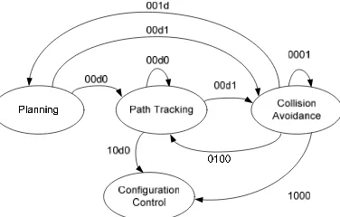
This section describes the integration of the four algorithms: global path planning, configuration control, path tracking controls, and collision avoidance, to move the vehicle from an initial to a goal configuration. The FSM in Fig. 1 is described as follows. The global planning algorithm produces a set of via points from an initial to a goal configuration. I f there is no obstacle along the way to the next via point, the vehicle excecutes the path tracking algorithm. On the other hand, if obstacle exists, the vehicle runs the collision avoidance algorithm. When the vehicle is at the state of collision avoidance, a timer to determine a given timeout is set. I f the vehicle has reached the next via point (or the final via point) within the given timeout, the vehicle runs the path tracking (or the configuration control) to go to the next via point. I f the given timeout has passed and the next or final via point has not been reached, the planning algorithm is excecuted. Thus, this prevents the vehicle to be trapped in the local minima by following a new planning. When the vehicle has reached the final via point and there is no obstacle along the way to the goal configuration, the algorithm is switched to configuration control. Then, the desired configuration of the vehicle is achieved.
3 5.3. Results
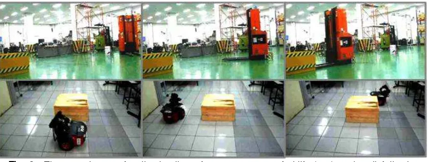
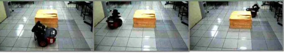
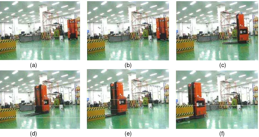
I n this section, the performance of the proposed navigation planning and control is investigated. Fig. 2 shows the experiment of the pallet loading from the initial to the pallet location and also a mobile robot performed wall following movement. At the initial position, the forklift calculated a set of via points from the initial to the goal point (pallet position) throuhgh A* algorithm. Then, it detected an obstacle along the way to the next via-point. The collision avoidance module was activated to avoid the obstacle and reach the next via-point. When the forklift reached the final via-point, it excecuted the configuration control to reach the goal position and orientation, and engaged the pallet.
Fig. 2. The experiment of pallet loading of an autonomous forklift (top) and wall following of a mobile robot (bottom)
5.4. Discussions and Conclusions
The control architecture of an autonomous wheeled-vehicle has been presented. The integration between the motion control developed in theories and the behavior-based control architecture was proposed to produce a fast movement, accident preventive motion, failure recovery action, and high precision motion for autonomous vehicles. A FSM that regulates the the planning and control algorithms was proposed. The proposed control structure integrated multiple sensors, feedback controls, and decision making in a modular fashion for automating a vehicle. The effectiveness of the proposed architecture was verified by experimental results of autonomous forklift transporting a pallet from an initial to a desired configuration and a mobile robot performing wall following.
6. LI ST OF RESEARCH OUTPUT
The research yields a software for mobile robot control interface (Fig. 3).
Fig. 3. Mobile robot control interface. The research provides the following papers:
1. Augie Widyotriatmo, Anugrah K. Pamosoaji, & Keum-Shik Hong, “Control architecture of an autonomous material handling vehicle,” I nternational Journal of Artificial I ntelligence, 8(S12), 2013
4
I I I . EVALUASI DI RI
1. CAPAI AN:
a. TUJUAN YANG TERTULI S DI PROPOSAL:
1) Skema integrasi algoritma perencanaan global, lokal, dan algoritma kontrol untuk navigasi robot beroda.
2) Membangun algoritma perencanaan global dan lokal.
3) Perancangan kontrol menggunakan metode medan potensial untuk perencanaan lokal. 4) Mendapatkan hasil pengujian eksperimen dari sistem integrasi algoritma yang diusulkan. b. TUJUAN YANG TELAH DI CAPAI :
1) Skema integrasi algoritma perencanaan global, lokal, dan algoritma kontrol untuk navigasi robot beroda.
2) Membangun algoritma perencanaan global dan lokal.
4) Mendapatkan hasil pengujian eksperimen dari sistem integrasi algoritma yang diusulkan. c. TUJUAN YANG BELUM DI CAPAI :
3) Perancangan kontrol menggunakan metode medan potensial untuk perencanaan lokal.
Alasan: Setelah dilakukan studi lebih lanjut, metode medan potensial untuk perencanaan lokal tidak cocok untuk digunakan pada kendaraan beroda. Hal ini dikarenakan adanya halangan (constraint) gerak dari kendaraan beroda tersebut, yang disebut nonholonomic constraint. Dengan demikian, maka algoritma perencanaan dan kontrol robot beroda ini diintegrasikan menggunakan metode lain, yaitu metode Finite State Machine (FSM).
2. PRODUK RI SET
Yang Dijanjikan Pada Proposal Yang Dihasilkan Pada Penelitian
Publikasi
1 (satu) Jurnal I nternasional dan 1 Prosiding I nternasional
Publikasi
1 (satu) Jurnal I nternasional:
A. Widyotriatmo, A. K. Pamosoaji, & Keum-Shik Hong, “Control architecture of an autonomous material handling vehicle,” I nternational Journal of Artificial I ntelligence, 8(S12), 2013 (accepted: 24 September 2012; published: 1 August 2013) 1 Prosiding I nternasional:
Augie Widyotriatmo, Anugrah K. Pamosoaji, Gi-Yong Hong, and Keum-Shik Hong, “Control architecture of multiple material handling vehicles,” Proceedings of the 2nd I nternational Conference on I nstrumentation, Control and Automation, Bandung, I ndonesia, Nov. 15-17, 2011.
Propototipe Perangkat lunak
robot beroda Propototipe Perangkat lunak robot beroda
HAKI - HAKI -
3. ALAMAT HOMEPAGE KK YANG BERI SI HASI L PENELI TI AN: http: / / ik.fti.itb.ac.id/ 4. KEGI ATAN DI SEMI NASI HASI L RI SET:
1. The 2nd I nternational Conference on I nstrumentation, Control and Automation, Bandung, I ndonesia, Nov. 15-17, 2011.
2. Workshop on the I EEE Conference on Control, Systems & I ndustrial I nformatics, Bandung, I ndonesia, Sep. 23-26, 2012
5. SI NERGI DENGAN KEGI ATAN DAN PROYEK RI SET LAI N:
Penulisan makalah bersama dengan Pusan National University Korea dengan proyek riset: the World Class University program granted by the National Research Foundation of Korea under the Ministry of Education, Science and Technology, Korea (grant no. R31-20004).
6. KEMANFAATAN PROYEK RI SET: Mahasiswa sarjana yang terlibat aktif:
1. Saqi K. Rauzanfiqr (Mhs. S1 Lulus Agustus 2012): 1 buah buku TA dan 1 buah paper prosiding pada konferensi internasional.
2. Ananta Adhi Wardana (Mhs. S1): prototipe perangkat lunak robot beroda pada P3DX, 1 buah buku TA, dan 1 buah paper prosiding pada konferensi internasional.
7. PERMASALAHAN YANG DI HADAPI DAN SARAN PERBAI KAN:
Tidak ada permasalahan yang berarti dalam peneilitian ini. Saran untuk perbaikan adalah biaya penelitian agar dapat ditingkatkan.
8. RENCANA KELANJUTAN PENELI TI AN:
I V. LAMPI RAN OUTPUT PENELI TI AN
1. Foto-foto prototipe:Arm
8x Sonar
Interface
Gambar I V. 1. Sensor dan komponen robot
Gambar I V. 2. I nterfacing robot dan komputer
International Journal of Artificial Intelligence (IJAI)
http://www.ceser.in/ijai.html
Paper: Control Architecture of an Autonomous Material Handling Vehicle Reference: IJAI-ICA2011-11
Dear Authors,
We are pleased to inform you that your paper is accepted for the International Journal of Artificial Intelligence (IJAI).
Please find the reviewers' reports with this. Please incorporate all comments and send the revised paper in the IJAI format.
Also please send the signed Copyright Form referred to also as "Copyright Transfer Agreement (CTA) form". It is available at
http://ceser.in/ceserp-home/ceser-cta.pdf.
The Instructions for authors that describe the IJAI format and also the LaTeX and the MS Word templates can be found in the dedicated section at
http://ceser.in/ceserp/index.php/ijai/about/submissions#authorGuidelines
The LaTeX Style Format is available at
http://ceser.in/ceserp-home/ijamas-latex-kit-all.zip.
The MS Word format (we need a doc file edited in MS Word 2003 with Equation Editor 3.0) is available at
http://ceser.in/ceserp-home/MS Word Example For.doc.
Also, please mention the Mathematics Subject Classification and the Computing Classification System if not given in your paper. You can find them at:
A. Mathematics Subject Classification (MSC):
(The information about the Mathematics Subject Classification (MSC) - available at: http://www.ams.org/msc/ )
B. Computing Classification System (CCS):
(The information about the ACM Computing Classification System - available at: http://www.acm.org/class/1998/ccs98.html )
---Reviewers' comments to the authors taken from the reviewers' reports:
Editor: This is an excellent paper. Plese check all references such that to be edited according to journal's style.
Current Folder: INBOX Sign Out
Compose Addresses Folders Options Search Help Calendar
Message List | Delete Previous | Next Forward | Forward as Attachment | Reply | Reply All Subject: Acceptance: International Journal of Artificial Intelligence (IJAI) -
IJAI-ICA2011-11
From: "Radu-Emil PRECUP" <[email protected]> Date: Mon, September 24, 2012 12:56 am
To: [email protected] (more)
Cc: "Editors-in-Chief of IJAI" <[email protected]> (more) Priority: Normal
12/12/12 Webmail Dosen Teknik Fisika ITB
2/2 https://dosen.tf .itb.ac.id/webmail/src/webmail.php
---Please fill in the recommendation form for IJAI at
http://science.thomsonreuters.com/info/journalrec/
Looking forward to receiving the revised paper in the required format and the signed CTA,
Sincerely,
Prof. Radu-Emil Precup Editor-in-Chief
International Journal of Artificial Intelligence (IJAI) E-Mails: [email protected] and [email protected] http://www.ceser.in/ijai.html
---Prof. Dr.Ing. Dipl.Math. Radu-Emil Precup "Politehnica" University of Timisoara Faculty of Automation and Computers
Department of Automation and Applied Informatics Bd. V. Parvan 2
RO-300223 Timisoara Romania
Phone: +40-256-403229,-403230,-403226 Fax: +40-256-403214
E-mail: [email protected] http://www.aut.upt.ro/~rprecup/
---Delete & Prev | Delete & Next
Control Architecture of an Autonomous Material
Handling Vehicle
Augie Widyotriatmo1, Anugrah K. Pamosoaji2 and Keum-Shik Hong3
1
Instrumentation and Control Research Group, Faculty of Industrial Technology, Bandung Institute of Technology; Ganesha 10, Bandung 40135, Indonesia;
Email: [email protected]
2
School of Mechanical Engineering, Pusan National University; 30 Jangjeon-dong Geumjeong-gu, Busan 609-735, Korea;
Email: [email protected]
3
Department of Cogno-Mechatronics Engineering and School of Mechanical Engineering, Pusan National University; 30 Jangjeon-dong Geumjeong-gu, Busan 609-735, Korea;
Email: [email protected]
ABSTRACT
In this paper, a control architecture that integrates path planning and motion control of an autonomous material handling vehicle is proposed. The three-layer architecture (deliberative, sequencing, and reflexive layers) is adopted. The deliberative layer plans a series of control actions for accomplishing tasks, the sequencing layer regulates the sequence of control modules and supervises the change of plan, and the reflexive layer collects sensory data and controls a specific motion. The control algorithms, which are derived considering sensor, environment, and kinematic constraints of the autonomous vehicle, assure the robustness against uncertainties as well as the safety during the motion. A finite state machine (FSM) that regulates the excecution of the planning and various control algorithms is proposed. The experimental results of a forklift transporting a pallet from an initial to a desired goal configuration demonstrate the effectiveness of the proposed control architecture.
Keywords: Autonomous vehicle, forklift, control architecture, path planning, motion control.
Mathematics Subject Classification: 68T40, 93C85
Computing Classification System: I.2.9
1. INTRODUCTION
Robotics research has been increased significantly in recent years. The applications of robotics
include material handling vehicles (Tamba, Hong, and Hong, 2009; Widyotriatmo, Hong, and Prayudhi,
2010), robot manipulator (Hassanein, Anavatti, and Ray, 2011), multi agent system for hose
transportation (Fernandez-Gauna et al., 2011), and others. The research subjects include localization
and vision systems (Takemura and Ishii, 2011; Bui and Hong, 2012), obstacle avoidance strategy (Bui
and Hong, 2010), control design (Nguyen, Hong, and Park, 2010; Turnip, Park, and Hong, 2010;
Haidegger et al., 2011; Joelianto and Wiranto, 2011), planning (LaValle, 2006), and the integration of
the components and algorithms (Hong, Tamba, and Song, 2008). This paper discusses the
control for an autonomous forklift that has two caster wheels in the front and one
drivable-and-steerable (driving) wheel in the rear.
The objective of an autonomous material handling vehicle is to transport materials from an initial to a
destination. A high speed movement, accident preventive motion, failure recovery action, and high
precision motion are demanded in the design of the autonomous material handling vehicle. To handle
such multiple objectives, different control modules need to be developed. Control architectures of
mobile robots have been developed in many approaches (Arkin, 1998). A purely reactive behavior has
been proposed in (Brooks, 1986). However, the purely reactive scheme does not perform well when
performing complex tasks. In (Arkin, 1992; Gerkey and Mataric, 2002), a behavior based control
architecture that has a hierarchical system consisting of a mission planner, a plan sequencer, and a
reactive system was proposed. In (Oreback and Christensen, 2003), three-layer architecture
(deliberative, sequencing, and reflexive layers) was proposed. The deliberative layer plans the tasks
given to the vehicle, the sequencing layer regulates action modules in the reflexive layer, and the
reflexive layer consists of resources (that collect data from various sensors), action modules (that
control a vehicle to perform various motions), and motor control modules (that regulate the motors in
the fashion that the desired commands given by an action module are followed).
Path planning algorithms generate a free collision path from an initial to a goal configuration based
upon a map information that provides sets of free-space and of obstacles (LaValle, 2006). Various
methods of path planning method are as follows: the grid-based search method assumes that each
configuration is identified by a grid point, and search algorithms are used to find a path from the start
to the goal avoiding obstacles; the cell decomposition method divides the map into polygonal region of
free space and obstacles; and sampling based algorithms represent a free space with a roadmap of
sampled configurations.
The control algorithms for a forklift become difficult since the forklift is a nonholonomic system (i.e., a
system with nonholonomic constraints). In (Brockett, 1983), it was shown that there is no continuously
differentiable time-invariant control law that stabilizes a nonholonomic system asymptotically. Two
control strategies for nonholonomic systems are found in the literature: open loop and closed loop
strategies. In open loop strategies (Murray and Sastry, 1993; Widyotriatmo, Hong, and Hong, 2009),
the control signals are calculated off-line using the information of the initial and the goal configurations.
Using this strategy, the vehicle may not reach the goal configuration due to disturbances, modeling
errors, and sensor uncertainties. In closed loop strategies, time-varying controls (Samson, 1995;
Tamba, Hong, & Hong, 2009) and discontinuous controls (Astolfi, 1996; Widyotriatmo and Hong, 2012)
have been proposed. The control signals are computed online based on the current and goal
configurations. A closed loop control can potentially compensate the uncertainties. In (Widyotriatmo
and Hong, 2011), a collision avoidance method which drives a forklift from an initial to a goal
configuration while avoiding collisions was investigated. In (Belta, Isler, & Pappas, 2005; Lindemann &
LaValle, 2009; Conner, Choset, and Rizzi, 2009), integration methods for planning and control of
algorithms for controlling the vehicle the was proposed. However, the methods assume static
obstacles, and the position of all of the obstacles are known
In this paper, the algorithms for the material handling task of the autonomous forklift are elaborated as
follows. A planning algorithm generates way-points from an initial configuration to a desired final
configuration based upon the map. The path planning algorithm is developed by two steps: A set of
points that include allowable position of the vehicle is determined from a given map; and the A*
algorithm in (LaValle, 2006) is used to obtain the shortest path from an initial to a goal. The control
algorithms includes path tracking algorithm to steer the forklift following a desired path, configuration
control to pick up or unload a pallet at a specified location, and collision avoidance algorithm to
prevent collision with dynamic and unmodeled obstacles. A FSM algorithm that integrates path
planning and control algorithms is proposed. It regulates the excecution of planing and motion control
algorithms in such away that the vehicle can accomplish the material transportation.
The contributions of the paper are as follows. First, the control architecture of the autonomous
material-handling vehicle is discussed. Second, the control modules required for the individual
material handling vehicles are investigated. Third, the reflexive layer structure, in which the control
modules are implemented, is elucidated. Fourth, the integration of path planning and control
algorithms for the material handling forklift is proposed. Fifth, the experimental results of the proposed
method are presented.
The paper is organized as follows. Section 2 describes the hardware configuration of the autonomous
forklift. Section 3 presents the software architecture of the autonomous forklift. Section 4 presents the
autonomous navigation controls. Section 5 demonstrates the experimental results of a forklift
transporting a pallet from an initial to a desired location. Section 6 draws conclusions.
2. HARDWARE CONFIGURATION
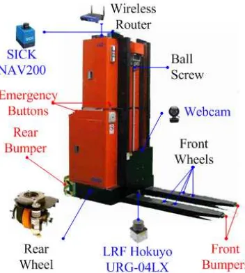
The hardware configuration of the autonomous vehicle is shown in Figure 1. Two AC motors drive and
steer the rear wheel and one AC motor drives a ball screw for the fork motion. Each forklift is
equipped with a laser-based localization sensor SICK NAV200 that measures its position and
orientation in a predefined global coordinate which is based upon known positions of reflectors. A
laser range finder (LRF) Hokuyo URG-04LX (range 4 m) provides the measurement of the distance
and the angle to obstacles. A webcam with a FOV of 50o (or 0.28π rad) is used to identify and
measure the configuration of a pallet. A wireless router is used for communication with the central
computer. The front and rear bumpers and emergency buttons are provided for safety.
In Figure 2, the hardware configuration of a forklift is shown including two controllers: an embedded
PC and a programmable logic controller (PLC). The PC receives the vehicle’s current configuration
from the NAV200, the distance and angle of obstacles from the LRF, the vision information from the
webcam, and a task from the central computer from the wireless router. It also provides control
commands (linear velocity and steering angle of the driving wheel and height position of the fork) to
Figure 1. The autonomous forklift.
Figure 2. Hardware configuration of the autonomous forklift.
The PLC controls three motors (driving, steering, and fork) by utilizing feedbacks from their individual
encoders such that the driving wheel and the fork follow the desired commands. It also receives the
signals from the three bumpers (two bumpers in the front and one bumper in the rear) and four
emergency buttons. The bumpers and the emergency buttons switches off the control signals to the
motor driver if they are activated. The PC communicates with the PLC, NAV200, and LRF via RS232
(serial port), with the webcam via USB, and with the wireless router via Ethernet.
3. CONTROL ARCHITECTURE
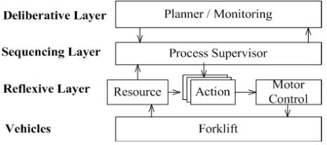
3.1. Three-layer architecture
Figure 3 depicts the three-layer (i.e., deliberative, sequencing, and reflexive) architecture. After a
vehicle is assigned to move a pallet to its destination, the deliberative layer plans a series of actions:
area, avoid collisions during movement, reach the goal configuration, and unload the pallet at the
desired configuration. The deliberative layer then enters a monitoring mode to begin checking the
results. The sequencing layer regulates a specific set of actions and also monitors the conditions of
every event. The sequencing layer will terminate an action, or replace them with a new action when a
monitoring event is triggered, when a timeout occurs, or when a new message is received from the
deliberative layer indicating a change of plan. The reflexive layer consists of resource, action, and
motor control. A resource represents a shared memory of sensor data. The data is utilized by the
action modules, the sequencing, and the deliberative layers. An action is a module to perform a
situated motion. In material handling vehicles systems, action modules include the following:
configuration control is to drive the vehicle from an initial to a specified goal configuration; path
tracking control is to move the vehicle following a particular path; and collision avoidance is to steer
the vehicle reaching a goal/sub-goal configuration while avoiding obstacles and other vehicles. Motor
control receives the desired control commands, converts them into proper signals, and controls the
motors such that the desired control commands are achieved.
3.2. Reflexive layer
Block diagram in Figure 4 shows the detail of the reflexive layer structure that is decomposed into two
loops: outer loop and inner loop. The outer loop, programmed in C++ on the embedded industrial PC,
generates three desired commands: the linear velocity (vd), the steering angle (δd) of the driving wheel,
and the fork height position (zd). These commands are updated upon the feedbacks from the sensors:
NAV200 provides position and orientation measurement (x, y, θ) with 10 Hz-frequency; LRF provides distance and angle of the i-th obstacle (ρi, θi); the webcam provides the configuration of the pallet (xg, yg, θg, zg); and the encoders provides the angular positions of the driving, steering, and fork motors (φr, φδ, φz). The inner loop, implemented in the PLC, generates three control signals (voltages uv, uδ, and uz) to control the three AC motors (driving, steering, and fork) in the fashion that the driving wheel and the
fork follow the desired commands. The three voltages are calculated from the desired commands and
the encoders’ feedback with the frequency of 100 Hz.
Figure 4. Block diagram of the reflexive layer.
4. PLANNING AND CONTROL ALGORITHMS
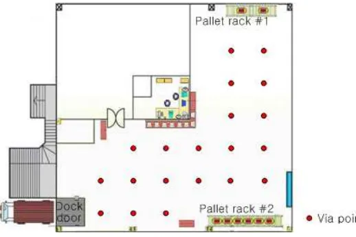
4.1. Global path planning
For the global planning strategy, via-points that provide a set of free space in a given workspace are
assigned. The via points can be generated using any path planning algorithm such as voronoi
diagram, cell decomposition, or sampling-based algorithm. In this paper, the via points are generated
manually since the static information of the map is known. The assignment of via points in the given
map is shown in Figure 5. To navigate the vehicles, paths are generated through the via-points from
the initial to the desired configurations. The sequence of the via-points for the individual vehicles is
computed in a discrete fashion using search algorithms. In this paper, the A* algorithm (LaValle, 2006)
is utilized in generating the path through via points from an initial to a goal configuration.
4.2. Forklift model
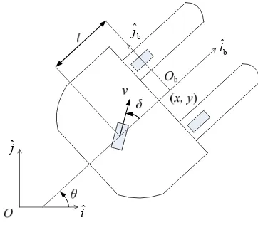
In Figure 6, O-iˆˆj represents the global coordinate frame that is fixed in the workspace. Ob-iˆbˆjb
denotes the body coordinate frame attached to the vehicle, Ob is the mid-point of the two front wheels
to which all the motions of the vehicle are generated, l denotes the distance between the center of
the rear wheel and the reference point Ob. The configuration of the vehicle is specified by position (x,
y) which is the coordinates of the reference point Ob and orientation which is the angle from the iˆ
-axis to the iˆb-axis. The velocity v and steering angle are the rear wheel’s linear velocity and
steering angle from the iˆb-axis, respectively. The equations of motion of the forklift are as follows (Widyotriatmo and Hong, 2012):
cos
cos
v
x , (1)
cos
sin
v
y , (2)
(v/l)sin , (3)
v v
f r v c v
m1 1 r , (4)
f
I , (5)
where
r
2 2 b 2 f r
1 r m I cos I /l sin I
m , (6)
/ / 2
cossinf f 2 b r
1 r I l I r m
c , (7)
mis the vehicle mass, Ib is the mass moment of inertia of the vehicle with respect to Ob, Iδ is that of
the rear wheel around the normal axis of the flat surface, If and Ir be the mass moments of inertia of
the front and rear wheels around their individual rolling axes, v and are the torque inputs vector to the driving and steering motors, respectively, fv and f are the surface frictions of the rear wheel in the rolling and steering directions, respectively.
b
ˆ
i
b
ˆj
j
ˆ
iˆ
The equations of motion of the forklift are consisted of two parts: Kinematic equations (1)-(3) describe
the configuration motion of the vehicle where the control commands are the linear velocity and the
steering angle of the driving wheel, and dynamic equations (4)-(5) provide the relationship between
the dynamics of the vehicle and the torques of the two AC motors (driving and steering). The two
parts of equations express the system in two (outer and inner) loops as described in Figure 4. The
control problem of the vehicle is solved in two stages: the desired input commands (linear velocity and
steering angle of the driving wheel) are designed based upon the kinematic equations, and the
voltage inputs supplied to the motors (driving and steering) are computed based upon the dynamic
equations. In this dissertation, a conventional PD control algorithm is implemented in the AC motor
control. In (Widyotriatmo and Hong, 2012), it was shown that the linear velocity vand the steering
angle tracks the desired commands vd and d with tracking errors ~vvvd and d
~
caused by the frictions and transient responses. As the load of the forklift mincreases, the response
converge slowly, and therefore, the two tracking errors (v~ and ~) also increase. It is assumed that
the load variation during motions is very small and by using the fixed gains of PD control, the linear
velocity vand steering angle can track their desired values vd and d with small bounded tracking
errors v~ ~v and ~ ~, where v~ and ~ are their bounds.
4.4. Configuration controls
In this section, the configuration (position and orientation) control (Widyotriatmo & Hong, 2011) that
drives the vehicle from an initial to a goal configuration and the path tracking control that steers the
vehicle to follow a determined path are developed. Let x~xgx, ~yygy, and ~g be the
configuration errors between the current and goal configurations. Three navigation variables are
introduced: ~2 ~2 y
x
is the distance error, and arctan2
~y,~x
and garctan2
~y,x~
arethe split portions of the orientation error (i.e., ~ = + ), in which is the portion from the vehicle’s moving direction to the goal point direction and is the remaining error at the goal frame. The
kinematic equations (1)-(3) using the introduced navigation variables become
vcos cos , (8)
v/ sin cos v/l sin , (9)
v/ sin cos . (10)
If the vehicle achieves its goal configuration, both and ~ ( + ) become zero. Let the polar coordinate system comprising and ~ be the error space. The control problem of moving a vehicle
from an initial configuration to a goal configuration becomes the asymptotic stabilization problem from
The movements of the vehicle from an initial configuration to a goal configuration are considered in
two ways: forward and backward. Whenever a goal point is in front of the vehicle, the forward
movement is chosen. Conversely, the backward movement is chosen when a goal point is behind the
vehicle. Consider the system (8)-(10). The control law with the goal points in front of the vehicle is
given as follows:
2uniformly asymptotically stable. The control law with the goal points behind the vehicle is given as
follows:
(14) can be found in (Widyotriatmo & Hong, 2011). The control law (11)-(12) drives the vehicle from
an initial to a goal configuration in forward movement, while the control law (13)-(14) steers the
vehicle in backward movement.
4.5. Path tracking control
The path tracking problem is formulated as a configuration control, in which the goal configuration
moves along the path s with the velocity s. In order that the vehicle can follow the motion of the goal
configuration, the velocity s is designed subject to the current-goal configuration errors of the vehicle.
The velocity s be chosen as
where vmaxis the maximum velocity of the vehicle and kq is a positive constant. The sign (positive or
negative) in (15) assigned the trajectory to be followed in forward or backward movement. Applying
(11)-(12) with the velocity of moving goal configuration smax(0,vmax(1/kq) 222), the
vehicle follows the assigned trajectory sin forward movement. Conversely, applying (13)-(14) with the
velocity of moving goal configuration max(0, (1/ ) 2 2 2)
max
v kq
s , the vehicle follows the
4.6. Collision avoidance
The collision avoidance control for the individual vehicle is derived based upon the navigation function,
that is a function in which the negative gradient of the function induces the vehicle to be attracted
toward a desired configuration and repelled against obstacles (Widyotriatmo and Hong, 2011). A
control law is designed based upon the negated gradient of the navigation function, so that the system
is driven from an initial configuration to a goal configuration as the elements in the system avoid
collisions. The navigation function is proposed as follows:
is proposed based upon the fact that a vehicle configuration that is close to and is directed to
obstacles should be avoided.
The control law is derived in such away that the time derivative of (16) is negative semi-definite. The
control law is (Widyotriatmo and Hong, 2011)
Then, the origin ( , , ) = (0, 0, 0) is uniformly asymptotically stable. The proof is found in
(Widyotriatmo & Hong, 2011). Using the control law (17) and (18), the forklift achieves a via point or a
goal configuration, and the collisions with obstacles and moving objects are avoided.
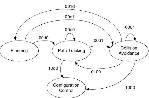
4.7. Integration of path planning and control
This section describes the integration of the four algorithms: global path planning, configuration
control, path tracking controls, and collision avoidance, to move the vehicle from an initial to a goal
configuration. The algorithms are excecuted by the FSM that regulates the four algorithms based
upon the vehicle conditions (Figure 7). The conditions are described as follows:
- FVP (final via point) is a condition whether the vehicle has or has not reached the final point.
FVP = 1 denotes that the final via point is reached, and FVP = 0 denotes that the final via
point is not reached.
- VP (via point) is a condition whether the vehicle has or has not reached the next via point. VP
= 1 denotes that the next via point is reached, and VP = 0 denotes that the next via point is
not reached.
- TO (timeout) is a condition whether the vehicle has or has not passed the timeout given to
reach the next point. TO = 1 denotes that the timeout is reached, and TO = 0 denotes that the
timeout is not reached.
- OB (obstacles) is a condition whether the vehicle does or does not detect obstacles along its
way to the next point. OB = 1 denotes that the vehicle detects obstacles, and OB = 0 denotes
that the vehicle does not detect obstacles.
Path Tracking
Configuration Control
Collision Avoidance 0001
Planning
FVP/VP/TO/OB
0100
1000 10d0
00d0 001d
00d0
00d1
00d1
The FSM in Figure 7 is described as follows. From Subsection 4.1, the global planning algorithm
produces a set of via points from an initial to a goal configuration. If there is no obstacle along the way
to the next via point, the vehicle excecutes the path tracking algorithm. On the other hand, if obstacle
exists, the vehicle runs the collision avoidance algorithm. When the vehicle is at the state of collision
avoidance, a timer to determine a given timeout is set. If the vehicle has reached the next via point (or
the final via point) within the given timeout, the vehicle runs the path tracking (or the configuration
control) to go to the next via point. If the given timeout has passed and the next or final via point has
not been reached, the planning algorithm is excecuted. Thus, this prevents the vehicle to be trapped
in the local minima by following a new planning. When the vehicle has reached the final via point and
there is no obstacle along the way to the goal configuration, the algorithm is switched to configuration
control. Then, the desired configuration of the vehicle is achieved.
5. EXPERIMENTAL RESULTS
In this section, the performance of the proposed navigation planning and control is investigated. Fig. 8
shows the experiment of the pallet loading from the initial to the pallet location. At the initial position,
the forklift calculated a set of via points from the initial to the goal point (pallet position) throuhgh A*
algorithm. Then, it detected an obstacle along the way to the next via-point. The collision avoidance
module was activated to avoid the obstacle and reach the next via-point. When the forklift reached the
final via-point, it excecuted the configuration control to reach the goal position and orientation, and
engaged the pallet.
(a) (b) (c)
(d) (e) (f)
(a) (b) (c)
(d) (e) (f)
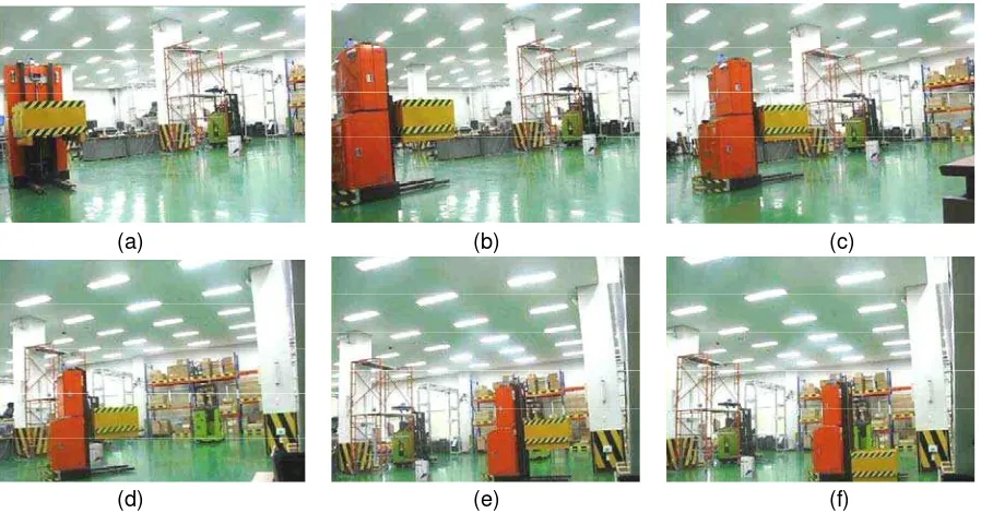
Figure 9. The experiment of pallet unloading: (a)-(d) the forklift tracks the via-points, (e)-(f) the forklift reached the final via point, performed configuration control, and unload the pallet.
Fig. 9 depicts the experiment of the pallet transfer from the pallet location to the destination. The
forklift calculated a set of via points from the initial to the goal point (pallet destination) through A*
algorithm. Since there is no obstacle along the way to the final via-point, the vehicle performed path
tracking control. When the final via point was reached, the configuration control was performed, and
the pallet was unload to the destination. In this experiment, the maximum speed of the vehicle was set
to 0.8 m/s. The forklift took 2 minutes to accomplish the task. The slow velocity was due to the low
rate of the sensors sampling time (i.e., the sampling time of the LRF and the vision processing were
500 ms and that of the NAV200 was 100 ms).
6. CONCLUSIONS
The control architecture of an autonomous forklift has been presented. The integration between the
motion control developed in theories and the behavior-based control architecture was proposed to
produce a fast movement, accident preventive motion, failure recovery action, and high precision
motion for autonomous vehicles. A FSM that regulates the the planning and control algorithms was
proposed. The proposed control structure integrated multiple sensors, feedback controls, and decision
making in a modular fashion for automating a forklift. The effectiveness of the proposed architecture
was verified by experimental results of autonomous forklift transporting a pallet from an initial to a
ACKNOWLEDGMENT
This work was supported by the World Class University program granted by the National Research
Foundation of Korea under the Ministry of Education, Science and Technology, Korea (grant no.
R31-20004) and the Research and Innovation Program ITB (grant no. 185/I1.C06/PL/2012) granted by the
Directorate General of Higher Education under the Ministry of National Education of Indonesia.
7. REFERENCES
Arkin, R. C., 1998, Behavior-Based Robotics. Cambridge, MA: MIT Press.
Arkin, R. C., 1992, Behavior-based robot navigation for extended domains. Adapt. Behav. 1, 201–
225.
Astolfi, A., 1996, Discontinuous control of nonholonomic systems. System. Control Lett.27, 37-45.
Belta, C., Isler, V., and Pappas, G. J., 2005, Discrete abstractions for robot motion planning and
control in triangular environments. IEEE Trans. Robot.21, 864-874.
Brockett, R. W., 1983, Asymptotic stability and feedback stabilization. Differential geometric control
theory. Birkhäuser.
Brooks, R. A., 1986, A robust layered control system for a mobile robot. IEEE J. Robot. Automat., 2,
14–23.
Bui, T. T. Q. and Hong, K.-S., 2010, Sonar-based obstacle avoidance using region partition scheme.
J. Mech. Sci. Technol. 24, 365-372.
Bui, T. T. Q. and Hong, K.-S., 2012, Evaluating a color-based active basis model for object
recognition. Com put . Vis. I m age Underst . 116, 1111-1120.
Conner, D. C., Choset, H., and Rizzi, A. A., 2009, Flow-through policies for hybrid controller synthesis
applied to fully actuated systems. IEEE Trans. Robot.25, 136-146.
Fernandez-Gauna, B., Lopez-Guede, J. M., Zulueta, E., Echegoyen, Z., Grana, M., 2011, Basic
results and experiments on robotic multi-agent system for hose deployment and transportation. Int.
J. Artificial Intelligence. 6, 183-202.
Gerkey, B. P., and Mataric, M. J., 2002, Sold!: Auction methods for multi-robot coordination. IEEE
Trans. Robot. Autom.8, 758-768.
Haidegger, T., Kovacs, L., Preitl, S., Precup, R.-E., Benyo, B., Benyo, Z., 2011, Controller design
solutions for long distance telesurgical applications. Int. J. Artificial Intelligence, 6, 48-71.
Hassanein, O. I., Anavatti, S. G., Ray, T., 2011, Robust position control for two-link manipulator. Int. J.
Artificial Intelligence. 7, 347-359.
Hong, K.-S., Tamba, T. A., and Song, J. B., 2008, Mobile robot architecture for reflexive avoidance of
Joelinato, E., and Wiranto, I., 2011, An application of ant colony optimization, Kalman filter, and
artificial neural network for multiple target tracking problems. Int. J. Artificial Intelligence. 7,
384-400.
LaValle, S. M., 2006, Planning Algorithms. Cambridge University Press.
Lindemann, S. R., and LaValle, S. M., 2009, Simple and efficient algorithms for computing smooth,
collision-free feedback laws over given cell decomposition. Int. J. Robot. Res.28, 600-621.
Murray, R. M., and Sastry, S. S., 1993, Nonholonomic motion planning: Steering using sinusoids.
IEEE Trans. Automat. Control, 38, 700-716.
Nguyen, L. H., Hong, K.-S., and Park, S., 2010, Road-frequency adaptive control for semi-active
suspension system. Int. J. Control Automat. System. 8, 1029-1038.
Oreback, A., and Christensen, H. I., 2003, Evaluation of architectures for mobile robotics. Auton.
Robot.14, 33-49.
Samson, C., 1995, Control of chained systems application to path following and time-varying point
stabilization of mobile robots. IEEE Trans. Automat. Control, 40, 64-77.
Takemura, Y., and Ishii, K., 2011, Auto color calibration algorithm using neural networks and its
application to RoboCup robot vision. Int. J. Artificial Intelligence. 7, 368-383.
Tamba, T. A., Hong, B., and Hong, K.-S., 2009, A path following control of an unmanned autonomous
forklift. Int. J. Control Automat. System. 7, 113-122.
Turnip, A., Park, S., and Hong, K.-S., 2010, Sensitivity control of a MR-damper semi-active
suspension. I nt . J. Precis. Eng. Manuf.11, 209-218.
Widyotriatmo, A., Hong, B., and Hong, K.-S., 2009, Predictive navigation of an autonomous vehicle
with nonholonomic and minimum turning radius constraints. J. Mech. Sci. Tech.23, 381-388.
Widyotriatmo, A., Hong, K.-S., and Prayudhi, L. H., 2010, Robust stabilization of a wheeled vehicle:
Hybrid feedback control design and experimental validation. J. Mech. Sci. Tech.24, 513-520.
Widyotriatmo, A. and Hong, K.-S., 2011, A navigation function-based control of multiple wheeled
vehicles. IEEE Trans. Indus. Electron.58, 1896-1906.
Widyotriatmo, A., and Hong, K.-S., 2012, Switching algorithm for robust configuration control of a
Control Architecture of Material Handling Vehicles
Augie Widyotriatmo Instrumentation and Control
Institut Teknologi Bandung Bandung,Indonesia
A. K. Pamosoaji, G.-Y. Hong
School of Mechanical Engineering Pusan National University
Busan, Korea [email protected],
Keum-Shik Hong
Department of Cogno-Mechatronics Engineering
Pusan National University Busan, Korea [email protected]
Abstract—This paper presents the architecture of autonomous material handling vehicles. The centralized coordination of multiple vehicles and three-layer architecture (deliberative, sequencing, and reflexive layers) are adopted. The navigation controls, including configuration control, visual servoing, path tracking, and collision avoidance, are developed. The finite state machine (FSM) that supervises the control modules to complete the material handling task is elucidated. The experimental results of a forklift transporting a pallet from an initial to a desired goal configuration are demonstrated.
Keywords-autonomous vehicles; finite state machine; forklifts; hardware configuration; control architecture; navigation controls
I. INTRODUCTION
The task of autonomous material handling vehicles is to transport materials from initial to their destinations autonomously. A fast movement, accident preventive motion, failure recovery action, and high precision motion are demanded in the design of material handling vehicles. To handle such multi-objective, different control modules need to be developed. This paper discusses the architecture that organizes the control modules for material handling vehicles.
Architectures of mobile robot control have been developed in different approaches [1]. For a single robot, a purely reactive behavior has been proposed in [2]. However, the purely reactive scheme does not perform well when performing complex tasks. In [3], a hybrid deliberate architecture that has a hierarchical system consisting of a mission planner, a plan sequencer, and a reactive system has been proposed. In [4], [5], three-layer architecture (deliberative, sequencing, and reflexive layers) was proposed. the deliberative layer plans the tasks given to the vehicle, the sequencing layer regulates action modules in the reflexive layer, and the reflexive layer consists of resources (that collect data from various sensors), action modules (that control a vehicle to perform various motions), and motor control modules (that regulate the motors in the fashion that the desired commands given by an action module are followed). In multiple robots, two different approaches have been proposed: the decentralized coordination [6], [7] and centralized coordination [8], [9]. In the decentralized coordination, a set of tasks are given to the individual vehicles, and the individual vehicles start to move to the closest unoccupied task, where the occupied tasks are recognized by communication among their neighbors. In the centralized coordination, the individual tasks are distributed to the
individual vehicles by a central computer, and the individual vehicles start to move after the tasks are given.
The main advantage of decentralized coordination is that the task allocation problem is solved by local coordination among a local neighborhood of vehicles. Hence, the complexity of the problem will not grow up as the number of vehicles increase. However, a group of vehicles can chase the same task while the workspace is limited. In this case, the navigation control problem of the individual vehicles becomes complicated (i.e., navigating a group of vehicles in a narrow workspace). On the other hand, the navigation control problem in the centralized coordination is simpler since one task is given to one vehicle before the individual vehicles begin to move. In this paper, the centralized coordination of multiple vehicles is adopted to avoid the complexity of the navigation control problem. Then, the three layer architecture is applied by reason of its ability in handling complex tasks.
In this paper, forklift vehicles that have two caster wheels in the front and one drivable-and-steerable (driving) wheel in the rear are the main subjects. The control modules, including configuration control in [10] (to load/unload a pallet at a specified location), pallet picking using visual servoing in [11] (to pick up a pallet at an arbitrary location based upon the information of the vision system), path tracking control (to follow the designed path), and collision avoidance in [12] (to avoid collisions with obstacles or other vehicles), is developed. The FSM that organizes the control modules for loading and unloading pallets from the initial to the destination is elucidated. An experimental result on the integration of control modules is demonstrated.
The contributions of the paper are as follows. First, the overall multiple material-handling vehicles system is discussed. Second, the control modules required for the individual material handling vehicles are investigated. Third, the reflexive layer structure, in which the control modules are implemented, is elucidated. Fourth, the integration of control modules for material handling vehicles is presented.
The paper is organized as follows. Section II describes the hardware configuration of the autonomous forklift. Section III presents the software architecture of multiple forklifts. Section IV presents the autonomous navigation controls. Section V demonstrates the experimental results of a forklift transporting a pallet from an initial to a desired location. Section VI draws conclusions.
2011 2nd International Conference on Instrumentation, Control and Automation 15-17 November 2011, Bandung, Indonesia
Figure 1. Centralized coordination of multiple vehicles, and equipments of a single vehicle.
II. HARDWARE CONFIGURATION
Fig. 1 shows the developed autonomous forklift that has two caster wheels in the front and one drivable-and-steerable wheel in the rear. Two AC motors drive and steer the rear wheel and one AC motor drives a ball screw for the fork motion. Each forklift is equipped with a laser-based localization sensor SICK NAV200 that measures its position and orientation in a predefined global coordinate which is based upon known positions of reflectors. A laser range finder (LRF) Hokuyo URG-04LX (range 4 m) provides the measurement of the distance and the angle to obstacles. A webcam with a FOV of 50o (or 0.28π rad) is used to identify and measure the configuration of a pallet. A wireless router is used for communication with the central computer. The front and rear bumpers and emergency buttons are provided for safety.
In Fig. 2, the hardware configuration of a forklift is shown including two controllers: an embedded PC and a programmable logic controller (PLC). The PC receives the vehicle’s current configuration from the NAV200, the distance and angle of obstacles from the LRF, the vision information from the webcam, and a task from the central computer from the wireless router. It also provides control commands (linear velocity and steering angle of the driving wheel and height position of the fork) to the PLC. The PLC controls three motors (driving, steering, and fork) by utilizing feedbacks from their individual encoders such that the driving wheel and the fork follow the desired commands. It also receives the signals from the three bumpers (two bumpers in the front and one bumper in the rear) and four emergency buttons. The bumpers and the emergency buttons switches off the control signals to the motor driver if they are activated. The PC communicates with the PLC, NAV200, and LRF via RS232 (serial port), with the webcam via USB, and with the wireless router via Ethernet.
III. CONTROL ARCHITECTURE
A. Centralized Coordination
Fig. 3 depicts the control scheme of multiple autonomous vehicles systems. A central computer has a role as the task
Figure 2. Hardware configuration of an autonomous forklift.
Figure 3. Centralized scheme of multiple vehicles and the three-layer (deliberative, sequencing, and reflexive) architecture.
coordinator and supervisor for the whole multiple vehicles operation. In the scheme of auction-based method for multiple vehicles task allocation [8], a central computer distributes each task to each vehicle. The task distribution protocol in the central computer is as follows: A user introduces the tasks (delivering pallets from their initials to their destinations), the central computer evaluates the distance between each vehicle’s current position to each pallet’s position, and a vehicle that has the closest distance to a pallet is assigned to take the pallet and to deliver it to its destination. After the tasks are allocated to the individual vehicles, the central computer monitors the progress.
B. Three-Layer Architecture
In the individual vehicles, the three-layer (i.e., deliberative, sequencing, and reflexive) architecture [5] is adopted. After a vehicle is assigned to move a pallet to its destination, the deliberative layer plans a series of actions: pick up the pallet using the information from vision system (visual servoing), follow a path/via-point directing to the goal area, avoid collisions during movement, reach the goal configuration, and unload the pallet at the desired configuration. The deliberative layer then enters a monitoring mode to begin checking the results. The sequencing layer regulates a specific set of actions and also monitors the conditions of every event. The sequencing layer will terminate an action, or replace them with a new action when a monitoring event is triggered, when a timeout occurs, or when a new message is received from the deliberative layer indicating a change of plan. The reflexive
2011 2nd International Conference on Instrumentation, Control and Automation 15-17 November 2011, Bandung, Indonesia
⎟
Figure 4. Block diagram of reflexive layer.
Dock door Via point A path made by the
planner Pallet rack #1
Pallet rack #2
Figure 5. Global planning: A* algorithm is used to connect via-points from the initial to the desired configurations.
layer consists of resource, action, and motor control. A resource represents a shared memory of sensor data. The data is utilized by the action modules, the sequencing, and the deliberative layers. An action is a module to perform a situated motion. In material handling vehicles systems, action modules include the following: Configuration control is to drive the vehicle from an initial to a specified goal configuration, visual servoing is to control the vehicle to an arbitrary target configuration using vision system, path tracking control is to move the vehicle following a particular path, and collision avoidance is to steer the vehicle reaching a goal/sub-goal configuration while avoiding obstacles and other vehicles. Motor control receives the desired control commands, converts them into proper signals, and controls the motors such that the desired control commands are achieved.
C. Reflexive Layer
Block diagram in Fig. 4 shows the detail of the reflexive layer structure that is decomposed into two loops: outer loop and inner loop. The outer loop, programmed in C++ on the embedded industrial PC, generates three desired commands: the linear velocity (vd), the steering angle (δd) of the driving wheel, and the fork height position (zd). These commands are updated upon the feedbacks from the sensors: NAV200 provides position and orientation measurement (x, y, θ) with 10 Hz-frequency, LRF provides distance and angle of the i-th obstacle (ρi, θi), the webcam provides the configuration of the pallet (xg, yg, θg, zg), encoders provides the angular positions of the driving, steering, and fork motors (φr, φδ, φz). The inner
loop, implemented in the PLC, generates three control signals (voltages uv, uδ, and uz) to control the three AC motors (driving,
steering, and fork) in the fashion that the driving wheel and the fork follow the desired commands. The three voltages are calculated from the desired commands and the encoders’ feedback with the frequency of 100 Hz.
IV. NAVIGATION CONTROLS
A. Global Planning
For the global planning strategy, the via-points are assigned in a given workspace. To navigate the vehicles, paths are generated through the via-points from the initial to the desired configurations. The sequence of the via-points for the individual vehicles is computed in a discrete fashion using the A* algorithm. In Fig. 5, paths made by the planner through via points are shown. If a path is blocked by unmodeled obstacles, the vehicle uses collision avoidance module to avoid the obstacle and to reach the next via-point. The complete navigation strategy is provided in the Section IVH.
2011 2nd International Conference on Instrumentation, Control and Automation 15-17 November 2011, Bandung, Indonesia
b
Figure 6. The forklift schematic.
B. Forklift Model
In Fig. 6, O-iˆjˆ represents the global coordinate frame that
is fixed in the workspace. Ob-iˆbˆjb denotes the body coordinate frame attached to the vehicle, Ob is the mid-point of the two front wheels to which all the motions of the vehicle are generated, l denotes the distance between the center of the rear wheel and the reference point Ob. The configuration of the vehicle is specified by position (x, y) which is the coordinates of the reference point Ob and orientation θ which is the angle from the iˆ -axis to the iˆb-axis. The velocity v and steering angle δ are the rear wheel’s linear velocity and steering angle from the iˆ -axis, respectively. The equations of b motion of the forklift are as follows:
δ moments of inertia of the front and rear wheels around their individual rolling axes, τv and τδ are the torque inputs vector
to the driving and steering motors, respectively, fv and fδ are
the surface frictions of the rear wheel in the rolling and steering directions, respectively.
C. AC Motor Control
The equations of motion of the forklift are consisted of two parts: Kinematic equations (1)-(3) describe the configuration motion of the vehicle where the control commands are the linear velocity and the steering angle of the driving wheel, and dynamic equations (4)-(5) provide the relationship between the dynamics of the vehicle and the torques of the two AC motors (driving and steering). The two parts of equations express the system in two loops (outer and inner), which is described in Section IIIC (Fig. 4). The control problem of the vehicle is solved in two stages: The desired input commands (linear velocity and steering angle of the driving wheel) are designed based upon the kinematic equations, and the voltage inputs supplied to the motors (driving and steering) are computed based upon the dynamic equations. In this dissertation, a conventional PD control algorithm is implemented in the AC motor control. In [10], it was shown that the linear velocity v
and the steering angle δ tracks the desired commands vd and the frictions and transient responses. As the load of the forklift
m increases, the response converge slowly, and therefore, the two tracking errors (v~ and δ~) also increase. It is assumed that the load variation during motions is very small and by using the fixed gains of PD control, the linear velocity v and steering angle δ can track their desired values vd and δd with small bounded tracking errors v~ ≤v~ and δ~≤δ~, where v~ and δ~ are their bounds.
D. Configuration Control
In this section, the configuration (position and orientation) control module [10] that drives the vehicle from an initial to a goal configuration is utilized. Let ~x=xg−x, ~y=yg−y, and
θ θ
θ = g−
~
be the configuration errors between the current and goal configurations. Three navigation variables are introduced:
2 from the vehicle’s moving direction to the goal point direction and φ is the remaining error at the goal frame. The kinematic equations (1)-(3) using the introduced navigation variables become
If the vehicle achieves its goal configuration, both ρ and θ~ (α + φ) become zero. Let the polar coordinate system
comprising ρ and θ~ be the error space. The control problem of moving a vehicle from an initial configuration to a goal
2011 2nd International Conference on Instrumentation, Control and Automation 15-17 November 2011, Bandung, Indonesia
configuration becomes the asymptotic stabilization problem from an arbitrary point in the error space to its origin.
Consider the system (8)-(10). The control law with the goal points in front of the vehicle is given as follows:
(
)
(
(
)
)
2 asymptotically stable. The proof and the control law when the goal points are behind the vehicle can be found in [10].E. Visual Servoing
The visual servoing problem is addressed as a configuration control with a field-of-view (FOV) constraint of the camera [11]. A camera, fixed at the reference point Ob, is utilized to identify the target feature and to measure the target configuration using the OpenCV library (www.intel.com). The principal axis of the camera always coincides with the iˆb-axis. Let the FOV of the camera be FOV = 2α < π. In order that the goal point always stays inside the boundaries of the view of the camera, the orientation error associated with the direction to the goal point (α ) is constrained by α <α <π/2.
Consider the system (8)-(10). Let the control law be chosen as follows: stable. The proof can be found in [11]. Using (13)-(14), the configuration error goes to zero, while the FOV constraint is not violated.
F. Path Tracking
The path tracking problem is formulated as a configuration control, in which the goal configuration moves along the path s
with the velocity s
.
In order that the vehicle can follow the motion of the goal configuration, the velocity s is designed subject to the current-goal configuration errors of the vehicle. The velocity s be chosen aspositive constant. Applying (11)-(12), the vehicle follows the assigned trajectory s.
G. Collision Avoidance
The collision avoidance control for the individual vehicle is derived based upon the navigation function, that is a function in which the negative gradient of the function induces the vehicle to be attracted toward a desired configuration and repelled against obstacles [12]. A control law is designed based upon the negated gradient of the navigation function, so that the system is driven from an initial configuration to a goal configuration as the elements in the system avoid collisions. Using the control law, multiple vehicles achieve the goal configuration, and the collisions with obstacles and moving objects are avoided.
H. Finite State Machine
In this section, the FSM that integrates the control modules is elucidated. Fig. 7 shows the FSM consists of 6 states. The individual states correspond to the following conditions:
1) PLANNING: This state dictates the vehicle to plan a path through the unblocked via-points from an initial to a desired position. The state is activated when the collision avoidance module cannot find a way to the next via point and when the forklift does not align with the pallet configuration.
2) MOVE_TO_PICK_UP: The state corresponds to the path tracking and visual servoing for pallet picking. When there is no obstacles, the path following is chosen.
3) MOVE_TO_GOAL: The state corresponds to the path tracking and configuration control for unload the pallet at a specified location.
4) COLL_AVOID: The state enables the vehicle to avoid static and moving obstacles and to reach the next via point or the desired configuration.
5) LIFT: In this state, the forklift reaches and lifts the pallet.
6) DROP: This vehicle reaches the desired position and unloads the pallet.
Figure 7. The FSM that organizes the control modules.
2011 2nd International Conference on Instrumentation, Control and Automation 15-17 November 2011, Bandung, Indonesia