UCalMiCeL - UNIFIED INTRINSIC AND EXTRINSIC CALIBRATION OF A
MULTI-CAMERA-SYSTEM AND A LASERSCANNER
M. Hillemanna,b∗, B. Jutzia
a
Institute of Photogrammetry and Remote Sensing, Karlsruhe{markus.hillemann, boris.jutzi}@kit.edu b
Fraunhofer Institute of Optronics, System Technologies and Image Exploitation, Ettlingen
Commission I/II, ICWG I/II
KEY WORDS:Calibration, Relative Pose, Orientation, Multi-Camera-System, Fisheye, Laserscanner
ABSTRACT:
Unmanned Aerial Vehicle (UAV) with adequate sensors enable new applications in the scope between expensive, large-scale, aircraft-carried remote sensing and time-consuming, small-scale, terrestrial surveyings. To perform these applications, cameras and laserscanners are a good sensor combination, due to their complementary properties. To exploit this sensor combination the intrinsics and relative poses of the individual cameras and the relative poses of the cameras and the laserscanners have to be known. In this manuscript, we present a calibration methodology for theUnified Intrinsic and Extrinsic Calibration of a Multi-Camera-System and a Laserscanner (UCalMiCeL). The innovation of this methodology, which is an extension to the calibration of a single camera to a line laserscanner, is an unifying bundle adjustment step to ensure an optimal calibration of the entire sensor system. We use generic camera models, including pinhole, omnidirectional and fisheye cameras. For our approach, the laserscanner and each camera have to share a joint field of view, whereas the fields of view of the individual cameras may be disjoint. The calibration approach is tested with a sensor system consisting of two fisheye cameras and a line laserscanner with a range measuring accuracy of30mm. We evaluate the estimated relative poses between the cameras quantitatively by using an additional calibration approach for Multi-Camera-Systems based on control points which are accurately measured by a motion capture system. In the experiments, our novel calibration method achieves a relative pose estimation with a deviation below1.8◦and6.4mm.
1. INTRODUCTION
Capturing spatial information with sensors carried by an Un-manned Aerial Vehicle (UAV) has become popular in recent years due to low costs and flexible field of applications (Armenakis, 2015). These new applications arise in the scope between ex-pensive, large-scale, aircraft-carried remote sensing and time-consuming, small-scale, terrestrial surveyings. A typical Un-manned Aerial System (UAS) is equipped with optical sensors for the purpose of documentation, localization of the UAS or map-ping of the environment. The localization task is often tackled by using Visual Odometry algorithms (Nist´er et al., 2004) or recently with approaches which utilize convolutional neural networks, like PoseNet (Kendall et al., 2015) or SqueezePoseNet (Mueller et al., 2017). Furthermore, Structure from Motion (SfM) approaches, like Bundler (Snavely et al., 2008) or visual Simultaneous Local-ization and Mapping (SLAM) algorithms additionally handle the task of mapping in 3D by using images from single cameras (En-gel et al., 2017), stereo cameras (Mur-Artal and Tard´os, 2016) or Multi-Camera-Systems (MCSs) (Urban and Hinz, 2016). Instead of reconstructing the environment by utilizing visual observations, range measurements with laserscanners are practicable and can lead to dense and accurate results (Bosse et al., 2012; Weinmann et al., 2017). The manufacturers of laserscanners see market po-tential in UAVs and launched several light weight products like the RIEGL miniVUX-1UAV, the SICK TIM551 or the Hokuyo UTM-30LX-EW in recent years. Further, the combination of cam-eras and laserscanners attached to an UAV provides a powerful tool to capture and analyze spatial information (Jutzi et al., 2014; Premebida et al., 2009).
∗Corresponding author.
MC1
L
MC2
L
MC2
C1
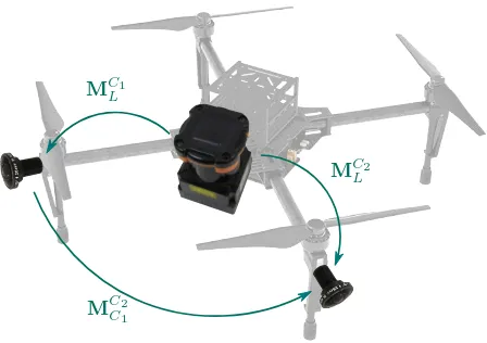
Figure 1: Sketch of an UAS with minimal configuration of sensors utilized by our calibration approach. The purpose of the calibration is to estimate the transformation matricesM.
For accurate spatial reconstructions the sensor system has to be geometrically calibrated, i.e. the intrinsics and relative poses of the individual cameras as well as the relative poses of the cameras and the laserscanner have to be known (Figure 1). Previous work concentrated on estimating the relative pose of cameras in a MCS and the relative pose of a single camera and a line laserscanner. In contrast, the purpose of our method, namelyUnified Intrinsic and Extrinsic Calibration of a Multi-Camera-System and a Laser-scanner (UCalMiCel1), is to estimate the relative poses of the
MCS and the laserscanner in an unified approach. Additionally to the calibration of the entire sensor system, with this approach, we offer an alternative calibration method of a MCS without joint fields of view. For this purpose the laserscanner is utilized to create a connection between the independent observations of the individual cameras. Either way, the cameras and the laserscanner have to share a joint field of view. Typical line laserscanners have fields of view of270◦or even360◦which makes it easy to achieve an overlap with the cameras.
Further, to receive ground truth to compare with, we implement a classical approach to calibrate a MCS by using accurately mea-sured control points. Thereby, we are able to evaluate the calibra-tion results quantitatively.
This manuscript is organized as follows. Previous work related to the calibration of a MCS and the calibration of a single camera and a line laserscanner is summarized in Section 2. In Section 3 the methodology of our novel calibration approach for the entire sen-sor system consisting of multiple cameras and a line laserscanner is described. For convenience the article is stated on the basis of one laserscanner. However, the approach can easily be adapted to a sensor system with multiple cameras and multiple laserscanners. The experiments and results of the introduced calibration approach are presented in Section 4. Finally, in Section 5, we conclude this contribution.
2. RELATED WORK
The calibration of a sensor system consisting of cameras and line laserscanners in previous work can be subdivided into the cali-bration of a MCS and the calicali-bration of a line laserscanner and a single camera. The calibration of a MCS can further be subdivided into methods assuming a joint field of view and methods that allow arbitrarily arranged but rigidly coupled cameras.
The calibration of a MCS with joint fields of view is well studied. The researchers use reference bars (Maas, 1999), laser-pointers respectively LED-markers (Baker and Aloimonos, 2000; Barreto and Daniilidis, 2004; Kurillo et al., 2008; Svoboda, 2003) or active self-calibration (Br¨uckner et al., 2014) to estimate the extrinsics of the cameras in a reference frame which consequently leads to the relative poses of the MCS. These methods are usually used to calibrate motion capture or rigid body tracking systems.
The task of calibrating a MCS with arbitrarily arranged, but rigidly coupled cameras is more challenging. The core challenge is to establish correspondence between the observations of the different cameras. This challenge can be tackled by moving the MCS in a field of control points, which are known in a reference frame (Blaser et al., 2017). For a method like this the control points have to be measured with an extra sensor like a tachymeter or a lasertracker. To deal with this drawback, other approaches use nat-ural features extracted in static environments. These approaches estimate the extrinsics of the cameras for different points of view and exploit the rigidity of the system to estimate the relative poses. The latter is usually performed by a nonlinear refinement step. The extrinsics are estimated by using Wide-Baseline Matching, Structure From Motion (Esquivel et al., 2007), Visual Odometry (Heng et al., 2013) or SLAM (Carrera et al., 2011; Urban and Hinz, 2016). These methods usually not only refine the calibration parameters, but also the intrinsics of the individual cameras and the estimated feature locations if applicable.
For the calibration of a line laserscanner to a single camera many approaches exist. Most of the approaches extract one or multiple planes in images taken from different points of view in conjunc-tion with corresponding points or lines in the observaconjunc-tion of the laserscanner. The calibration task is formulated as the registra-tion of the corresponding observaregistra-tions from the camera and the laserscanner. Many of the existing approaches make use of spe-cial calibration objects like triangles, folding patterns, cubes or more complex calibration objects consisting of multiple connected planes (Hu et al., 2016; Sim et al., 2016; Dong and Isler, 2016; Li et al., 2016; Chen et al., 2016; Kong et al., 2013; Yu et al., 2013). Most of these calibration objects are additionally equipped with checkerboards or markers. Thereby, the pose of the cam-era can be estimated from a single image. For practical reasons, the calibration methods which are mostly used deal with planar checkerboards like they are commonly utilized for intrinsic cam-era calibrations (Zhang and Pless, 2004; Zhou, 2014; Tulsuk et al., 2014; Vasconcelos et al., 2012). In contrast, the usage of scene corners avoids the need for special calibration objects (Gomez-Ojeda et al., 2015) which offers potential to be extended to a self-calibration technique.
Gr¨ater et al. (2016) follow a specific approach. They mention that many cameras are also sensible to electromagnetic radiation in the wavelengths emitted by laserscanners. This enables to directly measure the laserscanning projections in the images and thus to receive corresponding observations. However, this approach is not applicable to any type of sensor combination.
3. METHODOLOGY
To calibrate a sensor system consisting of multiple cameras and a line laserscanner in an unified approach, we extend the calibration procedure proposed by Urban and Jutzi (2017). This procedure was developed to calibrate line laserscanners to a single camera with a generic camera model, including pinhole, fisheye and om-nidirectional cameras. The calibration in Urban and Jutzi (2017) is an extension to The Robust Automatic Detection in Laser Of Calibration Chessboards (RADLOCC) toolbox (Zhang and Pless, 2004) and the minimal approach of registering a set of lines to a set of planes (Vasconcelos et al., 2012). These algorithms treat the calibration of a line laserscanner w.r.t. a single pinhole camera.
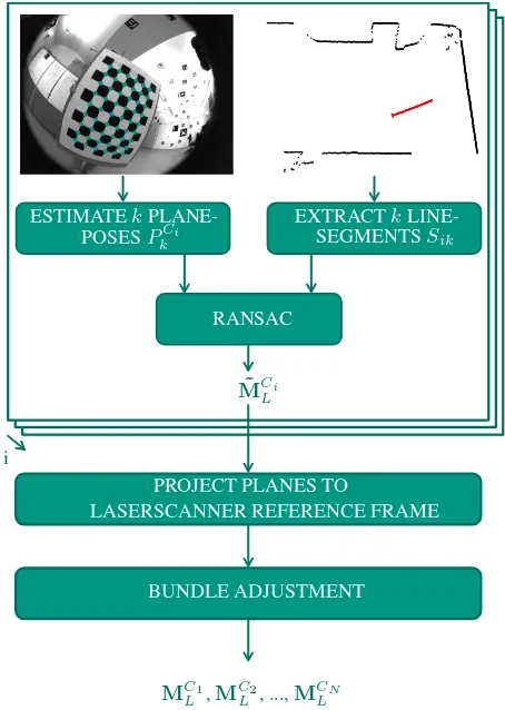
Section 3.1 states a formulation of our calibration approach. The details of the calibration described by Urban and Jutzi (2017) are recapitulated in Section 3.2 and the extension to the calibration of the entire sensor system namelyUCalMiCeLis described in Section 3.3. Figure 2 provides an overview of the methodology.
3.1 Problem Statement
The purpose of the calibration is to estimate the transformation matrixMM CS
L which maps laserscanner measurements to the ref-erence frame of the MCS and the transformation matricesMM CSC
i which represent the relative pose of the MCS w.r.t. cameraCi. Hereiis the index of a camera (i= 1, ..., N),Nis the number of cameras in the MCS andMare transformation matrices in
homogeneous representation.MM CS
L is determined by using the transformation matricesMCi
L that map the laserscanner measure-ments to each cameraCi:
MM CSL =MM CSC
i ·M
Ci
BUNDLE ADJUSTMENT
Figure 2: Calibration methodology. The top part depicts the estimation of a single camera to a laserscanner (Section 3.2). This part is performed for each cameraCi. The remaining projection and bundle adjustment are performed just once to calibrate the entire system (Section 3.3). For simplification the figure does not show the intrinsic camera calibration, which can also be estimated based on the calibration plane observed in different poses.
By defining the origin of the MCS reference frame as the origin of cameraC1and the rotation as the identity, Equation 1 can be
represented as
Therefore, the transformation matricesMCi
L that map the laser-scanner measurements to cameraCiare required. To estimate approximations for these transformation matrices, we process the procedure described in Section 3.2 for each cameraCi.
3.2 Estimating the Approximate Laserscanner to Single Cam-era TransformationsM˜Ci
L
Like the calibration procedure proposed by Zhang and Pless (2004) and Vasconcelos et al. (2012) our calibration requires a plane whose pose can be estimated from the images, e.g. a checker-board. The calibration plane is observed from cameraCiand the laserscanner in different posesk. This enables to estimate the in-trinsics of the individual cameras, by using a standard calibration approach like the ones proposed by Sturm and Maybank (1999) or Zhang (2000). The transformation matrixMCi
L is determined by utilizing the corresponding observations of the camera and the
laserscanner. Thus, we estimate the pose of the calibration plane from each image, e.g. in the case of a checkerboard by extracting the interest points and adjusting a plane to the points. In the next step of the procedure, all laserscanner points which correspond to the calibration plane are searched in the assigned observation. Finally, the approximate transformation matrixM˜Ci
L is estimated basically by using random sample consensus (RANSAC) like in the minimal approach of registering a set of lines to a set of planes (Vasconcelos et al., 2012).
3.3 Unified Bundle Adjustment
The procedure described in Section 3.2 provides approximate solutions to the laserscanner to single camera transformations
˜ MCi
L . Therefore, an initial guess for the transformation matrices
˜ MC1
Cj can be determined by utilizing Equation 2:
˜
In the final step ofUCalMiCeL, we exploit the rigidity of the entire sensor system by refining the transformation matricesM˜C1
Cj andM˜Ci
L in an unified bundle adjustment. Therefore, we project the planes extracted in the images of all cameras to the reference frame of the laserscanner:
ikis a plane w.r.t. the laserscanner reference frame in homogeneous representation at posekin cameraiandPCi
k de-notes a plane extracted in cameraCiat posekin homogeneous representation. Further, to obtain the optimal transformation ma-tricesMC1
Cj andM Ci
L in a least-squares sense, we minimize the distances of all extracted line-segmentsSikto their corresponding planesPCi
k .
By using all observations in an unified bundle adjustment this approach achieves a larger coverage of the field of view of the laserscanner and therefore better geometrical requirements for the pose estimation of the laserscanner compared to a single camera to laserscanner calibration.
4. EXPERIMENTS AND RESULTS
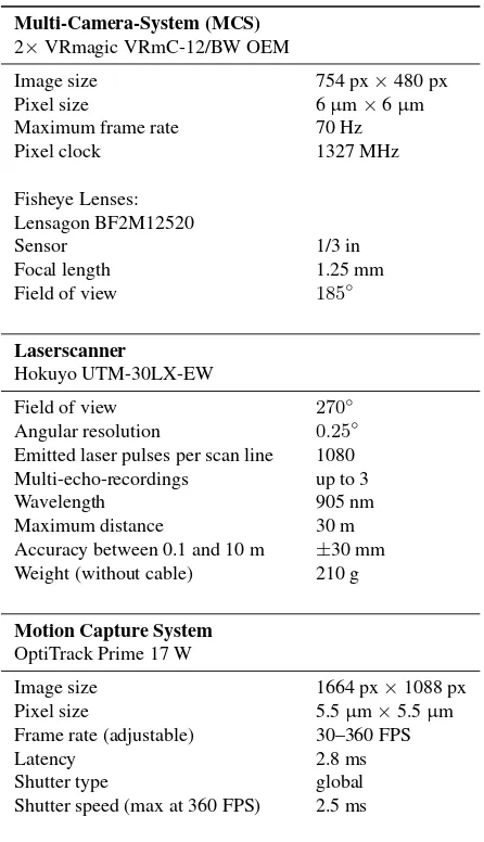
We performUCalMiCeLwith a sensor system consisting of two fisheye-cameras of the type VRmagic VRmC-12/BW OEM and a laserscanner of the type Hokuyo UTM-30LX-EW. The cameras are arranged with a divergent view angle. Due to the large field of view of the fisheye cameras of185◦, the images have a small overlap. However, the calibration approach doesn’t require a joint field of view. The laserscanner is mounted onto the front of the UAS in an oblique angle like it is sketched in Figure 1. It allows to scan the ground ahead of and next to the UAS. The laserscanner has a small size of62mm×62mm×87.5mmand a weight of 210g. Therefore and because of its low cost, it is frequently applied to UAS’s (Huh et al., 2013; Mader et al., 2015). Table 1 summarizes the specifications of all sensors used in our experiments.
Table 1: Specifications of all sensors used in the experiments.
Multi-Camera-System (MCS) 2×VRmagic VRmC-12/BW OEM
Image size 754 px×480 px
Pixel size 6µm×6µm
Maximum frame rate 70 Hz
Pixel clock 1327 MHz
Fisheye Lenses: Lensagon BF2M12520
Sensor 1/3 in
Focal length 1.25 mm
Field of view 185◦
Laserscanner
Hokuyo UTM-30LX-EW
Field of view 270◦
Angular resolution 0.25◦
Emitted laser pulses per scan line 1080 Multi-echo-recordings up to 3
Wavelength 905 nm
Maximum distance 30 m
Accuracy between 0.1 and 10 m ±30 mm Weight (without cable) 210 g
Motion Capture System OptiTrack Prime 17 W
Image size 1664 px×1088 px
Pixel size 5.5µm×5.5µm
Frame rate (adjustable) 30–360 FPS
Latency 2.8 ms
Shutter type global
Shutter speed (max at 360 FPS) 2.5 ms
We compare our calibration method with a method which uses control points. For our setup, we attach five markers used by a motion capture system to a standard checkerboard, which is commonly utilized for intrinsic camera calibrations. Thus, the 6DoF pose of the checkerboard w.r.t. the motion capture reference frame can be determined accurately. Moreover, we measure the position of the four outer checkerboard corners with the motion capture system and determine the position of each checkerboard corner w.r.t. the attached markers. Consequently, we obtain the exact position of every checkerboard corner in the motion capture reference frame.
The checkerboard is moved in front of the cameras with different orientations and distances. At any time the pose of the checker-board is tracked by the motion capture system with 360 frames per second and the positions of the checkerboard corners are computed. To determine the image points of the checkerboard corners in each image with subpixel-accuracy, we use a well-known detection algorithm by Geiger et al. (2012). Since we know the position of every checkerboard corner in the motion capture reference frame, we are able to compute the extrinsics of the camera in the reference frame based on 2D-3D correspondences by using OPnP (Zheng et al., 2013). We further refine the intrinsics of each individual camera and the extrinsics in a Levenberg-Marquardt optimization
Figure 3: Extracted segments in laserscanner reference frame which are used to estimate the pose of the laserscanner w.r.t. the MCS. Red dotted markers represent the segments that correspond to planes extracted in the left camera, blue dotted markers corre-spond to planes extracted in the right camera. The black asterisk represents the origin and the hatched area is the blind angle of the laserscanner. By using all observations in an unified adjustment, we achieve a larger coverage of the field of view of the laserscanner compared to a single camera to laserscanner calibration.
step, which minimizes the backprojection errors. Finally, we use the optimized intrinsics and extrinsics of the cameras to estimate the relative poses of the MCS by another Levenberg-Marquardt optimization. As we are able to create an arbitrarily dense set of control points with an intended spatial arrangement and with an accuracy of a few millimeters due to the motion capture system, we denote the result of this method as ground truth.
The data forUCalMiCeLare acquired as follows. We move the checkerboard in the joint field of view of the laserscanner and the cameras. While capturing, we stay for some seconds in the individ-ual positions to eliminate remaining errors in the synchronization of the cameras and the laserscanner as well as to increase the accuracy of the distance measurements of the laserscanner by av-eraging five consecutive observations. To ensure that the minimal solution described by Vasconcelos et al. (2012) estimates a correct pose of the scanner w.r.t. the cameras, a set of well distributed laserscanner segments with varying orientations is needed. Fig-ure 3 shows the extracted laserscanner segments in laserscanner reference frame which correspond to the extracted checkerboard planes. Note that outliers are already rejected by a RANSAC-step (Fischler and Bolles, 1981) during the estimation of the minimal solution by Vasconcelos et al. (2012).
In Table 2 the estimated parameters of the relative pose of the second camera w.r.t. the first camera (MC2
Table 2: Estimated Euler angles and translations from left to right camera
Method Euler Angles in◦ Translation inmm
Ground Truth [+116.23±0.04 −67.41±0.04 −93.25±0.02] [−118.52±0.30 −53.87±0.31 −132.30±0.25] Approx. Solution [+121.93±0.14 −67.48±0.10 −99.63±0.05] [−102.33±3.07 −26.25±3.11 −156.77±3.48] UCalMiCeL [+121.03±0.14 −67.86±0.08 −97.92±0.04] [−119.04±2.78 −46.98±2.94 −133.12±3.28]
Table 3: Relative Pose Error regarding to ground truth
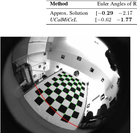
Method Euler Angles of RPE in◦ Translation of RPE inmm Approx. Solution [−0.29 −2.17 −1.11] [−15.82 +27.15 −25.23]
UCalMiCeL [−0.62 −1.77 −0.22] [+1.71 +6.37 −2.22]
Figure 4: Laserscanner segment backprojected to the image. Green plus markers represent the extracted interest points used for estimation of the plane pose. Red dotted markers represent the correspondent laserscanner points. Obviously, in the data used for calibration, the correspondent observations are a good match.
approximate solution. The final calibration result deviates a few millimeters from the ground truth calibration.
We also evaluate the resulting laserscanner to MCS Calibration visually by backprojecting the laserscanner points to the image. Thus, we use the estimated transformation matrixMC1
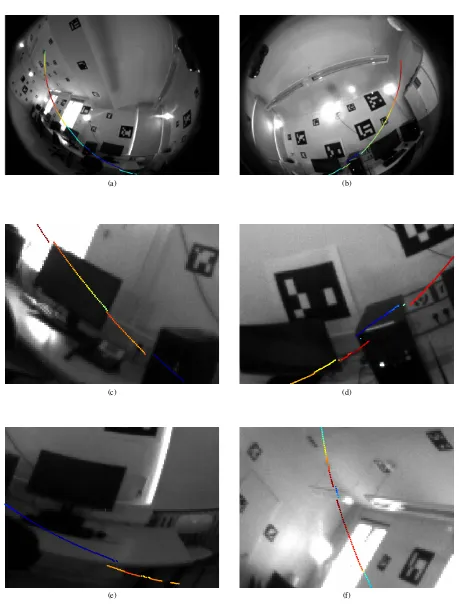
L and the intrinsics of the camera. Figure 4 shows a typical example of this backprojection for an image used in the calibration. The corre-sponding observations of the camera and the laserscanner match very well and the laserscanner points are flush-fitted and well aligned with the checkerboard plane. Moreover, to evaluate the quality in a common environment, Figure 5 presents the backpro-jected laserscanner observation in a desktop scene with concise depth-discontinuities. Figure 5a and 5b show the images of the two fisheye cameras. Figure 5c and 5d depict detailed views of these images. In the middle of Figure 5d a layover effect can be observed. The laserscanner pulses are reflected by the wall while the camera observes the computer case in the same image section. This parallax is caused by the distance between the optical center of the camera and the origin of the laserscanner. In case of Figure 5d the laserscanner is located at the left of the camera and conse-quently observes more points at the wall next to the computer case. In contrast, in Figure 5c, the laserscanner is located at the right of the camera. Therefore, some points at the left of the computer case seem to be missing. Finally, Figure 5e and 5f show two other examples of the parallax. In far ranges the effect of the parallax becomes smaller.
5. CONCLUSION
In this contribution, a novel unified approach for the intrinsic and extrinsic calibration of a sensor system consisting of multi-ple cameras and a laserscanner namelyUCalMiCeLis presented. The challenge of establishing a connection between the individual observations of multiple cameras without joint field of view is tackled by using a line laserscanner. In other words, for the cali-bration approach the laserscanner and the cameras have to share a joint field of view whereas the fields of view of the cameras may be disjoint. The calibration does not require a special preparation of the environment. It just necessitates a plane whose pose can be estimated based on the images, e.g. a checkerboard like it is frequently used for intrinsic camera calibrations. By considering all observations in an unified bundle adjustment this approach achieves a larger coverage of the field of view of the laserscan-ner and therefore better geometrical requirements for the pose estimation of the laserscanner compared to a single camera to laserscanner calibration.
We testUCalMiCeLwith a sensor system consisting of two fisheye cameras and a laserscanner on the basis of real data. To be able to evaluate the calibration results quantitatively, we moreover implement an additional approach for calibrating a multi camera system, which uses control points determined by a motion capture system. As we are able to create an arbitrarily dense set of control points with an intended spatial arrangement and with an accuracy of a few millimeters due to the motion capture system, we denote the result of this method as ground truth.
The results of the test calibrations show a Relative Pose Error of a few degrees and a few millimeter between the ground truth calibra-tion andUCalMiCeL. Due to the fact that the range measurement of the used laserscanner has a low quality with a standard deviation of30mm, the calibration result is very good. The good quanti-tative results are supported by the visual results which consist of a single laserscanner observation backprojected to the assigned image. The range measurements match the optical observations to an extent of a few pixel.
(a) (b)
(c) (d)
(e) (f)
References
Armenakis, C., 2015. (Editor).Proceedings of International Con-ference on Unmanned Aerial Vehicles in Geomatics (UAV-g). ISPRS - International Archives of the Photogrammetry, Remote Sensing and Spatial Information SciencesXL-1-W4, pp. 1–419.
Baker, P. and Aloimonos, Y., 2000. Complete calibration of a multi-camera network. In: Omnidirectional Vision, 2000. Proceedings. IEEE Workshop on, IEEE, pp. 134–141.
Barreto, J. and Daniilidis, K., 2004. Wide area multiple camera calibration and estimation of radial distortion. In:Proceedings of the 5th Workshop on Omnidirectional Vision, Camera Net-works and Non-Classical Cameras, Prague, Czech Republic, Vol. 63, p. 64.
Blaser, S., Nebiker, S. and Cavegn, S., 2017. System design, calibration and performance analysis of a novel 360 ¨a stereo panoramic mobile mapping system. ISPRS Annals of Pho-togrammetry, Remote Sensing & Spatial Information Sciences.
Bosse, M., Zlot, R. and Flick, P., 2012. Zebedee: Design of a spring-mounted 3-d range sensor with application to mobile mapping.IEEE Transactions on Robotics28(5), pp. 1104–1119.
Br¨uckner, M., Bajramovic, F. and Denzler, J., 2014. Intrinsic and extrinsic active self-calibration of multi-camera systems. Machine vision and applications25(2), pp. 389–403.
Carrera, G., Angeli, A. and Davison, A. J., 2011. Slam-based au-tomatic extrinsic calibration of a multi-camera rig. In:Robotics and Automation (ICRA), 2011 IEEE International Conference on, IEEE, pp. 2652–2659.
Chen, Z., Yang, X., Zhang, C. and Jiang, S., 2016. Extrinsic calibration of a laser range finder and a camera based on the au-tomatic detection of line feature. In:Image and Signal Process-ing, BioMedical Engineering and Informatics (CISP-BMEI), International Congress on, IEEE, pp. 448–453.
Dong, W. and Isler, V., 2016. A Novel Method for Extrinsic Calibration of a 2-D Laser-Rangefinder and a Camera.arXiv preprint arXiv:1603.04132.
Engel, J., Koltun, V. and Cremers, D., 2017. Direct sparse odom-etry. IEEE Transactions on Pattern Analysis and Machine Intelligence.
Esquivel, S., Woelk, F. and Koch, R., 2007. Calibration of a multi-camera rig from non-overlapping views. In:Joint Pattern Recognition Symposium, Springer, pp. 82–91.
Fischler, M. A. and Bolles, R. C., 1981. Random sample consen-sus: a paradigm for model fitting with applications to image analysis and automated cartography. Communications of the ACM24(6), pp. 381–395.
Geiger, A., Moosmann, F., Car, ¨O. and Schuster, B., 2012. Auto-matic camera and range sensor calibration using a single shot. In:Robotics and Automation (ICRA), 2012 IEEE International Conference on, IEEE, pp. 3936–3943.
Gomez-Ojeda, R., Briales, J., Fernandez-Moral, E. and Gonzalez-Jimenez, J., 2015. Extrinsic calibration of a 2d laser-rangefinder and a camera based on scene corners. In:Robotics and Automa-tion (ICRA), 2015 IEEE InternaAutoma-tional Conference on, IEEE, pp. 3611–3616.
Gr¨ater, J., Strauss, T. and Lauer, M., 2016. Photometric laser scanner to camera calibration for low resolution sensors. In: Intelligent Transportation Systems (ITSC), 2016 IEEE 19th International Conference on, IEEE, pp. 1552–1557.
Heng, L., Li, B. and Pollefeys, M., 2013. Camodocal: Automatic intrinsic and extrinsic calibration of a rig with multiple generic cameras and odometry. In: Intelligent Robots and Systems (IROS), 2013 IEEE/RSJ International Conference on, IEEE, pp. 1793–1800.
Hu, Z., Li, Y., Li, N. and Zhao, B., 2016. Extrinsic Calibration of 2-D Laser Rangefinder and Camera From Single Shot Based on Minimal Solution.IEEE Transactions on Instrumentation and Measurement65(4), pp. 915–929.
Huh, S., Shim, D. H. and Kim, J., 2013. Integrated navigation system using camera and gimbaled laser scanner for indoor and outdoor autonomous flight of uavs. In:Intelligent Robots and Systems (IROS), 2013 IEEE/RSJ International Conference on, IEEE, pp. 3158–3163.
Jutzi, B., Weinmann, M. and Meidow, J., 2014. Weighted data fusion for uav-borne 3d mapping with camera and line laser scanner.International Journal of Image and Data Fusion5(3), pp. 226–243.
Kendall, A., Grimes, M. and Cipolla, R., 2015. Posenet: A convo-lutional network for real-time 6-dof camera relocalization. In: Proceedings of the IEEE international conference on computer vision, pp. 2938–2946.
Kong, J., Yan, L., Liu, J., Huang, Q. and Ding, X., 2013. Im-proved Accurate Extrinsic Calibration Algorithm of Camera and Two-dimensional Laser Scanner. Journal of Multimedia 8(6), pp. 777–783.
Kurillo, G., Li, Z. and Bajcsy, R., 2008. Wide-area external multi-camera calibration using vision graphs and virtual calibration object. In: Distributed Smart Cameras, 2008. ICDSC 2008. Second ACM/IEEE International Conference on, IEEE, pp. 1–9.
Li, N., Hu, Z. and Zhao, B., 2016. Flexible extrinsic calibration of a camera and a two-dimensional laser rangefinder with a folding pattern.Applied Optics55(9), pp. 2270.
Maas, H.-G., 1999. Image sequence based automatic multi-camera system calibration techniques1.{ISPRS}Journal of Photogram-metry and Remote Sensing54(56), pp. 352 – 359.
Mader, D., Blaskow, R., Westfeld, P. and Maas, H., 2015. Uav-based acquisition of 3d point cloud-a comparison of a low-cost laser scanner and sfm-tools. The International Archives of Photogrammetry, Remote Sensing and Spatial Information Sciences40(3), pp. 335.
Mueller, M. S., Urban, S. and Jutzi, B., 2017. SqueezePoseNet: Image based pose regression with small convolutional neural networks for uas navigation.Proceedings of International Con-ference on Unmanned Aerial Vehicles in Geomatics (UAV-g). ISPRS Annals of the Photogrammetry, Remote Sensing and Spatial Information Sciences.
Mur-Artal, R. and Tard´os, J. D., 2016. ORB-SLAM2: an open-source SLAM system for monocular, stereo and RGB-D cam-eras.arXiv preprint arXiv:1610.06475.
Nist´er, D., Naroditsky, O. and Bergen, J., 2004. Visual odometry. In: Computer Vision and Pattern Recognition, 2004. CVPR 2004. Proceedings of the 2004 IEEE Computer Society Confer-ence on, Vol. 1, Ieee, pp. I–I.
Premebida, C., Ludwig, O. and Nunes, U., 2009. Lidar and vision-based pedestrian detection system.Journal of Field Robotics 26(9), pp. 696–711.
Snavely, N., Seitz, S. M. and Szeliski, R., 2008. Modeling the world from internet photo collections. International journal of computer vision80(2), pp. 189–210.
Sturm, P. F. and Maybank, S. J., 1999. On plane-based camera calibration: A general algorithm, singularities, applications. In: Computer Vision and Pattern Recognition, 1999. IEEE Computer Society Conference on., Vol. 1, IEEE, pp. 432–437.
Svoboda, T., 2003. Quick guide to multi-camera self-calibration. ETH, Swiss Federal Institute of Technology, Zurich, Tech. Rep. BiWi-TR-263, http://www. vision. ee. ethz. ch/svoboda/SelfCal.
Tulsuk, P., Srestasathiern, P., Ruchanurucks, M., Phatrapornnant, T. and Nagahashi, H., 2014. A novel method for extrinsic parameters estimation between a single-line scan LiDAR and a camera. In:Intelligent Vehicles Symposium Proceedings, 2014 IEEE, IEEE, pp. 781–786.
Urban, S. and Hinz, S., 2016. MultiCol-SLAM - A modu-lar real-time multi-camera SLAM system. arXiv preprint arXiv:1610.07336.
Urban, S. and Jutzi, B., 2017. Lafida - A laserscanner multi-fisheye camera dataset.Journal of Imaging3(1), pp. 5.
Vasconcelos, F., Barreto, J. P. and Nunes, U., 2012. A Mini-mal Solution for the Extrinsic Calibration of a Camera and a Laser-Rangefinder.IEEE Transactions on Pattern Analysis and Machine Intelligence (PAMI)34(11), pp. 2097–2107.
Weinmann, M., Mueller, M. S., Hillemann, M., Reydel, N., Hinz, S. and Jutzi, B., 2017. Point cloud analysis for UAV-Borne laser scanning with horizontally and vertically oriented line scanners - concept and first results.Proceedings of International Conference on Unmanned Aerial Vehicles in Geomatics (UAV-g). ISPRS Archives of the Photogrammetry, Remote Sensing and Spatial Information Sciences.
Yu, L., Peng, M., You, Z., Guo, Z., Tan, P. and Zhou, K., 2013. Separated Calibration of a Camera and a Laser Rangefinder for Robotic Heterogeneous Sensors.International Journal of Advanced Robotic Systems10(10), pp. 367.
Zhang, Q. and Pless, R., 2004. Extrinsic calibration of a camera and laser range finder (improves camera calibration). In: Pro-ceedings of the IEEE/RSJ Conference on Intelligent Robots and Systems (IROS), Vol. 3, IEEE, pp. 2301–2306.
Zhang, Z., 2000. A flexible new technique for camera calibration. IEEE Transactions on pattern analysis and machine intelligence 22(11), pp. 1330–1334.
Zheng, Y., Kuang, Y., Sugimoto, S., Astrom, K. and Okutomi, M., 2013. Revisiting the PnP problem: A fast, general and optimal solution. In:Proceedings of the International Conference on Computer Vision (ICCV), pp. 2344–2351.