PRICISE TARGET GEOLOCATION AND TRACKING BASED ON UAV VIDEO
IMAGERY
H.R.Hosseinpoor, F.Samadzadegan, F. DadrasJavan*
School of Surveying and Geospatial Information Engineering, College of Engineering, University of Tehran - (hosseinpoor, samadz, fdadrasjavan)@ut.ac.ir
Youth Forum
KEY WORDS: Video, RTK, Geolocation, Kalman Filter, Unmanned Aerial Vehicle
ABSTRACT:
There is an increasingly large number of applications for Unmanned Aerial Vehicles (UAVs) from monitoring, mapping and target geolocation. However, most of commercial UAVs are equipped with cost navigation sensors such as C/A code GPS and a low-cost IMU on board, allowing a positioning accuracy of 5 to 10 meters. This low accuracy cannot be used in applications that require high precision data on cm-level. This paper presents a precise process for geolocation of ground targets based on thermal video imagery acquired by small UAV equipped with RTK GPS. The geolocation data is filtered using an extended Kalman filter, which provides a smoothed estimate of target location and target velocity. The accurate geo-locating of targets during image acquisition is conducted via traditional photogrammetric bundle adjustment equations using accurate exterior parameters achieved by on board IMU and RTK GPS sensors, Kalman filtering and interior orientation parameters of thermal camera from pre-flight laboratory calibration process. The results of this study compared withcode-based ordinary GPS, indicate that RTK observation with proposed method shows more than 10 times improvement of accuracy in target geolocation.
1. INTRODUCTION
Achieving accurate position deals great challenges when commercial small unmanned platforms are used. Since payload weight and size in small UAVs are limited, they can only carry very light sensors. Such sensors usually have poor performance which lowers the accuracy of localizing ground targets. Global Positioning Systems (GPS) and Inertial Measurement Units (IMU) can provide information of the UAV location and attitude. However, information about objects covering by the UAV imaging sensor, is not easily discerned from the limited sensor hardware available without the aid of a human operator (Beard, 2012), (Madison, 2008). Besides, small and light active devices, such as radars and lasers, are not available to allow airborne applications on small platforms. Among the suite of possible sensors, a video camera is inexpensive, lightweight, fits the physical requirements of small UAVs, and has a high information to weight ratio (Mallick 2007).
Thus, precise ground target localization from video imagery is crucially essential. (Ivey, 2005), (Campbell, 2006), (Redding, 2006), (Pachter, 2007), (Conte, 2008), (Quintero, 2010) (Sharma, 2013), (Shukla, 2014).
The detection of a ground target within the image frame can be performed automatically using video tracking. Video sequence object tracking consists of determining the image coordinates of an object of interest in consecutive video frames. One possible approach is to use the mean shift algorithm to localize the target object (Comaniciu, 2003).
The target coordinates can be calculated using the UAV position, attitude and the camera orientation relative to the UAV body. The UAV position is given by an on-board GPS receiver, while the attitude angles are computed from a navigation filter which integrates the inertial sensors (gyroscopes, magnetometer and accelerometers) and the GPS
(Barton 2012). However, by using this approach to solve the localization problem, both lateral and vertical positioning errors of the GPS receivers will contribute to the sources of error for target’s location estimation. These errors can be additive and result in ground resolution with up to tens of meters.
RTK-GPS is a differential GPS procedure that is based on car-rier phase GNSS (Global Navigation Satellite System) observations and leads to relative positions between a master and a rover station with centimetre accuracy in real time. The challenge of developing such a system for micro- and mini-sized UAVs is to stay within the space and weight limitations of the platforms. That is why only a few studies conducted by now, dealing with the integration of a RTK-GPS system on micro- or mini-sized UAVs (Rieke, 2011), (Stempfhuber, 2011).
The rest of this paper is organized as follows. Section 2 reviews the related literature in detection and localization of targets. Section 3 discusses the proposed localization algorithm via UAV based on stationary landmarks in details. The testbed setting and experimental results are discussed in Section 4, which shows the effectiveness of the proposed work, and finally, Section 5 concludes this paper and suggests future work ideas.
2. BACKGROUND AND RELATED WORK
Applying computer vision methods in UAV applications field have been continuously improved in recent years to process captured image sequences and videos from the environment to produce numerical or thematic information for making decisions (Beard, 2012). In this paper, computer vision based methods are applied to detect, identify, and accurately geolocating unknown targets of interest.
(Redding, 2006) applied localizing stationary targets without considering terrain slopes using a UAV with a gimbaled
camera. they also apply recursive least square filtering to the image sequenceand account for navigation biases and wind to improve accuracy up to 3m with no differential GPS.They also explored the problem of flight path optimization by finding an optimal altitude and radius for a circular trajectory above the stationary target. Due to its symmetry, a circular trajectory leads to a lower target localization error making it widely accepted as the optimal trajectory. The geo-location methodology developed in (Pachter, 2007), which requires multiple target bearing measurements, can be easily adapted to multiple UAV operations and cooperative geo-location, and the tracking of moving targets. The main result is that the target’s position and the UAV’s systematic attitude measurement errors can be jointly estimated using linear regression, provided the measurement errors are sufficiently small.
In (Ponda, 2008) authors explore problem of simultaneous target estimation and vehicle trajectory optimization and the resulting algorithms produce vehicle trajectories that increase the information provided by the measurements, greatly enhancing the target estimation performance, removing biases, improving filter convergence, increasing estimation, and overall leading to improved target localization. More accurate target localization can be obtained by registering the aerial images to a geo-referenced image provided by a Geographic Information System (GIS) database. In (Quintero, 2010) the video-based measurement model, the geo-location error and the UAV system dynamics are discussed. The proposed dynamic programming approach is developed, including a quantized relative state space and cost function. Simulation results are presented for two scenarios in which different target speeds are considered. (Shukla, 2014) utilized automatic feature based registration on technique of a georeferenced satellite image with an aerial image which is already stored in UAV’s database to retrieve the geolocation of the target.
3. PROPSED METHOD
This paper presents a real-time process for the identification and geolocation of ground targets based on thermal video imagery acquired by small UAV equipped with RTK GPS.
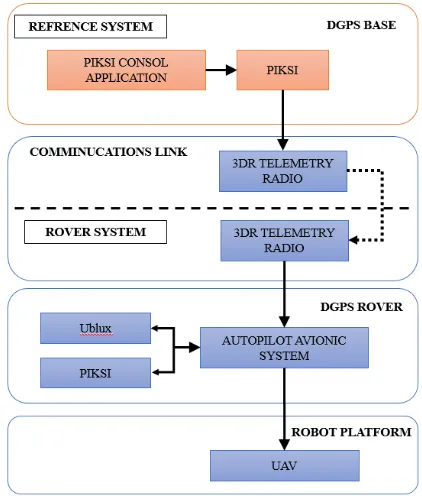
The diagram of the proposed framework is shown in Fig. 1. It includes three main steps, as target detection and tracking, real time positioning, target localization, and estate estimation which will be discussed in detail in the following subsections.
Figure 1: Flowchart of the proposed framework
3.1 Real Time Kinematic Positioning
Traditional Global Positioning System (GPS) uses the time differences between signals transmitted from satellites to a receiver which then digitally processes the data in order to find a location. This traditional method however, has an accuracy error of approximately ~10m. In Real Time Kinematic GPS, there is a Base station module on the ground as well as a Rover. As long as the Rover and the Base maintain at least 5 satellites in common, there can be a more accurate locational prediction of the Rover by adjusting the corrections determined by the Base station. This RTK solution can provide centimetre grade accuracy of the position, and should cause a greater than 200 times increase in accuracy in comparison with traditional GPS. The major benefits are the extreme precision of the GPS unit for any application, with an option for real time tracking, it will be a crucial player in the future of UAV technology.
The RTK GPS hardware is developed by PIKSI Fig. 2 (Swift Navigation, 2016). PIKSI is a fairly low cost, two module RTK GPS which allows us to see the GPS positioning in real time. Additionally, the trackable measurements such as time, latitude, longitude and altitude, are presented in a CSV file which allows to compare RTK positioning with GPS positioning.
Figure 2: UAV avionic with RTK
3.2 Target Detection and Tracking
Object tracking purpose is to find the targets between the consecutive frames in image sequences. Many tracking algorithms have been proposed and implemented to overcome difficulties that arise from noise, occlusion, clutter, and changes in the foreground objects or in the background environment.
Figure 3: Example of target interesting for tracking
Amongst various tracking algorithms, mean shift tracking algorithms have recently become popular due to their simplicity and robustness, (Comaniciu, 2003). The mean shift algorithm was originally invented by (Fukunaga, 1975) for data clustering. Recently this method successfully applied it to image segmentation and tracking. In these mean shift tracking algorithms, a colour histogram is used to describe the target region. The information theoretic similarity measures are commonly employed to measure the similarity between the template (or model) region and the current target region (Comaniciu, 2003). Tracking is accomplished by iteratively finding the local minima of the distance measure functions using the mean shift algorithm. Fig. 4.
Figure 4: Target tracked in the sequence of successive frames
3.3 Target Localization
To estimate the 3D coordinates of ground target, target position is computed by intersecting the ray starting from the camera centre and passing through the target pixel location in the image plane with the ground.
In this section, the method are described for locating the stationary target in the navigation coordinate system. In order to achieve this objective, relation between coordinate frame
3.3.1 Coordinate Frames and Conversion
The Localization algorithm uses a number of coordinate frames and considers transformations of 3-vectors among coordinate frames. We assume that all coordinate frames are right-handed and orthogonal.
The inertial coordinate Frame (I) is an earth-fixed coordinate system with its origin at the defined home location. As shown in Fig 1. This coordinate system is sometimes referred to as a north-east-down (NED) reference frame. It is common for north to be referred to as the inertial x direction, east to be referred to as the inertial y direction, and down to be referred to as the inertial z direction. The transformation from vehicle frame to body frame is given by:
uav points east, and z points toward the centre of the earth.
The body frame (b) is vehicle-carried and is directly defined on the body of the flying vehicle. Its origin is the centre of mass, x direction points out the nose of the airframe, y direction points out the right wing, and z direction points out the belly. The transformation from vehicle frame to body frame is given by
( , , ) ( ) ( ) ( ) representing the orientation of a body in three dimensions.
Figure 5: The orientation of the sensor frame (S frame) relative to the inertial coordinate frame (I frame).
The sensor frame (S) - The origin of the S frame is at the optical centre of the camera with geodetic coordinates. The z axis is along the general downward direction along the optical axis. The x axis is to the right hand side of the image .The y axis completes the right-handed coordinate frame. The image points and normalized image points are expressed in the S frame (ux ,vx ,f). Using similar triangles in Fig. 5: direction vector to the target as:
2 2 2
The geolocation data is filtered using an extended Kalman filter, which provides a smoothed estimate of target location.
This section presents a method for determining the location of objects in world/inertial coordinates using a video camera on board a UAV. From the Fig. 1 we have the relationship. (Beard 2012).
The only element on the right-hand side of equation 5, which is unknown is L. Therefore, solving the geolocation problem reduces to the problem of estimating the range to the target L. If digital elevation model is not available, simple strategy for
3.4.1 Geolocation using extended Kalman filter: The geolocation estimate in equation 8 provides a one-shot estimate of the target location. Unfortunately, this equation is highly sensitive to measurement errors, especially attitude estimation errors of the airframe. In this section we will describe the use of the extended Kalman filter (EKF) to solve the geolocation problem. If we assume the object is stationary the state vector of dynamic system is given by:
The prediction step for filter corresponding to the target is given by:
Where the Pk is the state covariance matrix for the target at time step k, ∆t is the sampling period and Fk is the system Jacobian measurement equation, assuming that GPS noise is zero-mean Gaussian. However the measurement model update for this
where H is the measurement Jacobian given by:
evaluation of proposed method. The custom design of the multi-rotor allows us to mount all the necessary devices needed to perform target geo-location. The platform is equipped with small thermal video camera and with appropriate sensors and autopilot to perform stabilized and autonomous flights. The autopilot unit includes MEMS gyroscopes and accelerometers, a 3-axis magnetic sensor, a barometric pressure sensor and a single frequency low-cost GPS receiver and a low-cost, high-performance GPS receiver with Real Time Kinematics (RTK) functionality for decimetre level positioning accuracy.
A base station and a rover station can cover a service area of about 10 square kilometers. The data transition is in real time using a wireless VHF modem. The cooperation of these navigation components allows horizontal and vertical stabilized positioning of the whole system as well as the position hold, return to the launch site or other various features including the mission flying.
The specifications of thermal camera are presented in Table 1.
Parameters Values
Detector type Uncooled FPA
Pixel pitch 17 µm
IR resolution 640×480
Focal length 25
Frequency 50 Hz
Sensitivity <65mk@f/1.0 Table 1: Thermal camera specification
4.1 Geometric Calibration
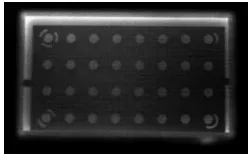
Geometric calibration of thermal camera with planar pattern is performed in laboratory. The test field consists of a grid of 28 regularly sized circle with 4 coded targets cut out of a thin non-conductor material. The size of mask pattern is 44×24 cm2, diameter of squares are 20 mm which spaced with 50 mm separation. Fig. 6 shows the thermal imagery acquired from mask based calibration pattern. The pattern is held in front of a powered computer monitor.
Figure 6. Thermal imagery for calibration
By starching, thermal image contrast is increased. Then sub-pixel accurate positions of the centre of each circle is defined. Self-calibration is performed to compute camera calibration parameters. The results of camera calibration are presented in Table 2.
Parameters Values SD
C 25.8655 0.525
xp 0.0085 0.235
yp -0.9934 0.235
K1 -5.54162e-004 1.1728e-003 K2 1.46497e-004 1.17294e-004 K3 -8.38681e-004 1.0917e-005 P1 -7.2475e-004 3.984e-004 P2 -6.5166e-004 6.079e-004 B1 1.1377e-002 2.241e-003 B2 1.3384e-002 3.548e-003
Table 2; Thermal camera specification
4.2 Flight Data
Flight test is performed over an industrial area surrounded by agricultural areas to verify the positioning accuracy of the proposed direct geolocation process.
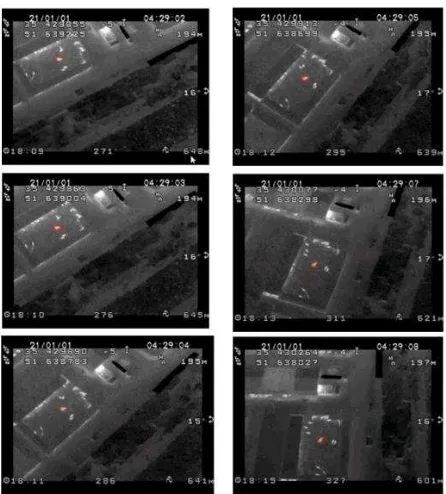
We attached thermal camera to the end effector of commercial multirotor UAV platform and programmed the UAV to follow a certain trajectory on top of the assigned area. In order to compare changes in altitude for target geolocation, recording video was performed from two different flight altitudes. Thermal video recorded 10 frame per second and the flight velocity is 6 m/s. Fig. 7 demonstrates some of extracted frames.
Figure 7: Frame extracted from thermal video
For accuracy assessment of proposed method, 3D dense DSM of the area which is generated from visible aerial imagery is applied. Fig. 8. Deviation of extracted coordinates for each object from proposed algorithm with respect to DSM based coordinate considered as the measure of accuracy.
Figure 8: 3D dense reference data
4.3 RESULT
The operator selected twenties interest targets by clicking on the first frame. Using mean-shift tracking algorithm the target tracked in subsequent framesand coordinate of the centre of the target computed from geolocation algorithm in sensor frame. First we use intersection of tow rays from stereo frame to compute location of selected target. Then, the proposed method to track and estimate target position applied with an extended Kalman filter. Coordinates of targets are extracted and compared to those extracted from reference data. Extracted coordinates for presented target in Fig. 9 are presented in table 3.
Figure 9: Target tracked in the sequence of successive frames
method DN(m) DE(m) DN(m) DE(m)
Table 3: Standard deviation in geolocation for selected target in 60m altitude and 120m altitude
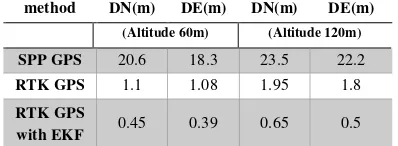
The coordinates for all extracted points are determined based on developed process. Mean standard deviation of coordinates with respect to reference data for all target extracted and shown in
Table 4: Comparison of mean standard deviation geolocation results using 60m and 120m as UAV flight altitude, with
respect to 3D dense reference data
5. CONCLUSION
In this paper, an algorithm capable of estimating target geo-location based on video imagery acquired by small UAV equipped with RTK GPS is developed. Results are compared with positioning accuracy acquired with code-based ordinary GPS instead of RTK which shows improvement of accuracy to decimetres. Therefore, it can be concluded that the proposed platform is relatively safe and fairly inexpensive for collecting critical spatial information for urgent response such as disaster relief and assessment applications where GCPs are not available.
REFRENCES
Barton, J. D., 2012. Fundamentals of small unmanned aircraft flight. Johns Hopkins APL technical digest 31(2): 132-149.
Beard, R. W., 2012. Small unmanned aircraft: Theory and practice, Princeton University Press.
Campbell, M. E., 2006. A vision based geolocation tracking system for UAVs. Proceedings of the AIAA Guidance, Navigation, and Control Conference and Exhibit.
Conte, G., 2008. High accuracy ground target geo-location using autonomous micro aerial vehicle platforms. Proceedings of the AIAA-08 Guidance, Navigation, and Control Conference.
Comaniciu, D., Ramesh, V. and Meer, P., 2003. Kernel-based object tracking. Pattern Analysis and Machine Intelligence, IEEE Transactions on,25(5), pp.564-577.
Eling, C., 2014. A precise direct georefrncing system for UAVS., Proceedings of the Workshop on UAV-basaed Remote Sensing Methods for Monitoring Vegetation.Kölner Geographische Arbeiten, 94. Köln:33-41
Fukunaga, K., 1975. The estimation of the gradient of a density function, with applications in pattern recognition. Information Theory, IEEE Transactions on, 21(1), pp.32-40
Ivey, G.F., 2005. Investigation of methods for target state estimation using vision sensors. , AIAA Guidance, Navigation, and Control Conference and Exhibit, San Francisco, CA, Aug.
Madison, R., 2008. Target geolocation from a small unmanned aircraft system. Aerospace Conference, 2008 IEEE, IEEE.
Mallick, M., 2007. Geolocation using video sensor measurements. Information Fusion, 2007 10th International Conference on, IEEE.
Pachter, M., 2007. Vision-based target geolocation using feature tracking. AIAA Guidance, Navigation and Control Conference and Exhibit, Hilton Head, South Carolina.
Quintero, S.A., 2010. Optimal UAV coordination for target tracking using dynamic programming. Decision and Control (CDC), 2010 49th IEEE Conference on, IEEE.
Rieke, M., 2011. High-precision positioning and real-time data processing of UAV-systems. International Archives of Photogrammetry, Remote Sensing and Spatial Information Sciences 38: 1-C22.
Redding, J.D., 2006. Vision-based target localization from a fixed-wing miniature air vehicle. American Control Conference, 2006, IEEE.
Sharma, R., 2013. Cooperative Sensor Resource Management for Multi Target Geolocalization using Small Fixed-wing Unmanned Aerial Vehicles. AIAA Guidance, Navigation, and Control.
Shukla, P., 2014. Automatic geolocation of targets tracked by aerial imaging platforms using satellite imagery.
International Archives of the Photogrammetry, Remote Sensing and Spatial Information Sciences 1: 1213-1220.
Stempfhuber., 2011. A precise, low-cost RTK GNSS system for UAV applications. International Archives of Photogrammetry, Remote Sensing and Spatial Information Science 38: 1-C22.
Swift Navigation., 2016. https://www.swiftnav.com/piksi.html (28 Mar, 2016).