REVISED COORDINATES FOR APOLLO HARDWARE
R. V. Wagner*, E. J. Speyerer, K. N. Burns, J. Danton, M.S. Robinson
Lunar Reconnaissance Orbiter Camera, School of Earth and Space Exploration, Arizona State University, Tempe, AZ, USA, 85287-3603 – rwagner@ser.asu.edu
KEY WORDS: Georeferencing, Geodesy, Identification, Reference Data, Accuracy
ABSTRACT:
The Narrow Angle Camera (NAC) on the Lunar Reconnaissance Orbiter provides direct imaging, at pixel scales of 0.5 to 1.0 meter, of anthropogenic equipment left on the Moon. We identified the descent stages of the lunar modules, central stations of the Apollo Lunar Surface Experiments Package, Laser Ranging Retroreflectors (LRRRs), and Lunar Roving Vehicles in each NAC image of the Apollo landing sites. The pixel coordinates of those objects were then converted to latitude and longitude coordinates using SPICE routines in the U.S. Geological Survey Integrated System for Imagers and Spectrometers. For images that contained an LRRR, pointing information was updated to match the well known LRRR coordinates. Final coordinates for each object are reported as averages from multiple images. NAC observations allow refinement of the locations of these objects and result in a more accurate geodetic referencing at these historic sites. Additionally, the anthropogenic coordinate analysis enables realistic error estimates for NAC derived coordinates for features anywhere on the Moon.
* Corresponding author.
1. INTRODUCTION
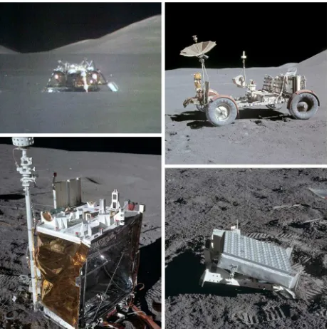
The positions of the three Apollo Laser Ranging Retroreflectors (LRRRs), along with the retroreflectors on the two Soviet Lunokhod rovers, are known to centimeter-level accuracy (Williams, 1996, 2008). The relative positions of the Apollo Lunar Surface Experiment Package (ALSEP) central stations at all six Apollo sites are known to 30 m accuracy from very long baseline interferometry (VLBI) experiments (King, 1976). Previous work by Davies and Colvin in 2000 combined these two datasets, using ground-level image photogrammetry and the historic United States Geological Survey (USGS) landing site maps to determine the relative positions of the Apollo LRRRs, ALSEP central stations, lunar module descent stages (LM), along with almost fifty notable craters. Analysis of Lunar Reconnaissance Orbiter Camera (LROC) Narrow Angle Camera (NAC) images provides the means to improve on this earlier work through identification of a wider set of objects on the surface, such as the Lunar Roving Vehicles, or LRVs (Figure 1). Furthermore, due to well-constrained position and orientation information for the Lunar Reconnaissance Orbiter (LRO), NAC images are used to directly measure feature locations to high accuracy (±22 m). With the additional accuracy provided by an LRRR within an image, we can measure the locations of human artifacts to an even higher level of confidence (±2m).
2. METHODS
2.1 Image Selection
Each object of interest was identified in multiple NAC images; identifications were confirmed by comparisons to ground-level Apollo handheld photographs. For objects that extend over more than one NAC pixel, the center pixel was used for coordinate computation.
NAC images were analyzed if they fell within the time period where improved orbital positioning information is available from radiometric and Lunar Orbiter Laser Altimeter (LOLA)
cross-over analysis, which improves the spacecraft position uncertainty to <20 m (Mazarico, 2012). The improved spacecraft position kernels are currently available from the start of the mission through 11 December 2011. Additionally, images from the LRO commissioning phase (3 July to 15 September 2009) were not included for two reasons: First, the spacecraft ephemeris is less accurate during this time period. Second, the spacecraft was in a higher orbit during the commissioning phase, with image resolutions ranging from 1-1.5 m at the Apollo sites, making it difficult to confidently identify pieces of hardware smaller than the LRV.
Finally, a subset of images (no more than three per site, usually only one) were dropped for each site because NAC derived Figure 1: The objects identified at each site. Clockwise from
top left: LM descent stage, LRV, LRRR, ALSEP central station.
hardware coordinates disagreed with the NAC average values by more than 50 m. The cause of these outlier estimates is under investigation. elevation and the elevation from laser ranging (Williams 2010), and applying that difference to the whole NAC DTM. The vertical offsets at all three LRRR sites were <2 m.
To calculate each object’s coordinates, the corresponding image is projected on a sphere with a radius equal to the object’s elevation. This strategy mitigates parallax errors from inexact surface intersections due to small errors in spacecraft position or pointing knowledge. To determine the coordinates of a pixel, the instrument line of sight for that pixel is intersected with a shape model. If that model is a DTM rather than a sphere, then the differences in elevation around the correct point can magnify ephemeris errors. This problem primarily affects the longitude of coordinates in off-nadir images, but there are many off-nadir images of the Apollo sites, as they were high-priority targets that were imaged on many orbits that did not pass directly over the sites.
2.3 Ground Coordinates
To compute the ground coordinates of an object from a line and sample pair in an non-map-projected NAC image, we used the CAMPT function in the Integrated System for Imagers and Spectrometers (ISIS) (Anderson, 2004), which in turn uses routines in the NASA Navigation and Ancillary Information Facility's (NAIF) SPICE Toolkit. CAMPT calculates ground coordinates from pixel coordinates using the relevant kernel files, which define the absolute locations and orientations of the spacecraft, instrument, and target. The two key time dependent kernels in this case are the spacecraft kernel (SPK), which contains the spacecraft position relative to the Moon for a given time period, and the camera kernel (CK), which contains orientation information for the spacecraft and instruments over time. CAMPT uses the appropriate kernels to determine the instrument location and pointing when each pixel was imaged, and intersects the line of sight for that pixel with a shape model of the Moon to determine the ground coordinates of that pixel.
After preparing an appropriate shape model as described earlier, the largest remaining position uncertainty, on the order of 50 m, is due to temperature dependent NAC pointing errors. These errors were corrected using temperature- and slew-dependent CK files that our team developed, which reduce the average absolute positioning error to ±15 m in both latitude and longitude (Speyerer, 2012). This correction modifies the camera pointing relative to the spacecraft body based on the temperature of the structure to which the NACs are mounted, and the angle the spacecraft is slewed towards or away from the Sun. The latter may be a proxy for differential heating across the mounting points, although the exact physical mechanism is unknown. See Speyerer et al. (this volume) for further discussion.
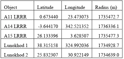
2.3.1 LRRR Sites: At the Apollo 11, 14, and 15 sites, the LRRRs enable accurate control of the spacecraft pointing (Table 1). For each image, we updated the camera pointing using the DeltaCK function of ISIS, which updates the cross-track and down-track components of the camera pointing to align the image with a known point, assuming the estimated spacecraft position is correct. We then collected and averaged the locations of each object from these corrected images. This method restricted the usable images to those where the LRRR was visible, but dramatically reduced the variation (to ±2 m at most) in calculated hardware positions as compared to the sites without LRRRs (Table 2).
Object Latitude Longitude Radius (m)
A11 LRRR 0.673440 23.473073 1735472.7
A14 LRRR -3.644170 342.521352 1736336.1
A15 LRRR 26.133396 3.628507 1735477.3
Lunokhod 1 38.315158 324.992036 1734928.7
Lunokhod 2 25.832307 30.922149 1734639.0
Table 1: Laser ranging derived coordinates for the five lunar retroreflectors, from Williams (2008) (Apollos and Lunokhod 2)
and Murphy (2011) (Lunokhod 1). These values, and all others reported in this paper, are in mean Earth/polar axis coordinates.
2.3.2 Sites with no LRRR: At the Apollo 12, 16, and 17 sites, there is no reference point with coordinates known to similar or better accuracy than the NAC pixel size (the ALSEP central station positions are only known to ±30 m (Davies and Colvin, 2000)). Thus, at these locations, hardware coordinates were calculated by using the average latitude and longitude from all NAC images in which each object is visible (Table 2).
3. RESULTS
The calculated positions for each object, along with the uncertainties in each measurement, are shown in Table 2.
4. DISCUSSION
4.1.1 Accuracy of Davies and Colvin estimates: The difference between coordinates derived by Davies and Colvin (2000) and the those reported here were generally close to the ALSEPs at Apollos 14 and 15 relative to the LRRRs. At Apollo 14, the ALSEP position was off by 6 m in latitude, longitude, and altitude, although the Apollo 15 ALSEP was only off by 3 m in longitude. We note that the published USGS maps (A11, A12, A14) and sketch maps in the mission preliminary science reports (A15, A16, A17), which were used by Davies and Colvin to locate the LMs relative to the ALSEPS, are good to International Archives of the Photogrammetry, Remote Sensing and Spatial Information Sciences, Volume XXXIX-B4, 2012
Calculated Location Standard Deviation (m) Range (m) Delta Davies (m)
Object Lat Lon Radius (m) Lat Lon Lat Lon Lat Lon Radius Images
Table 2: Coordinates derived from averaging estimates from multiple images. Bold lines indicate sites where image pointing was corrected using LRRR coordinates. Five decimal place precision in latitude and longitude corresponds to roughly 30cm precision at
these latitudes.
4.1.2 Locating arbitrary objects: The absolute position of any point in a NAC image is usually known to within 30 m on the lunar nearside, although there are outliers, allowing any object’s location to be determined to similar accuracy to Davies and Colvin (2000) estimates. Repeat coverage, such as exists at the Apollo sites, improves coordinate estimates by averaging out remaining random errors in the spacecraft ephemeris. On the farside the accuracy is not as easily computed and is probably lower due to poorer knowledge of local gravity variations and lack of direct spacecraft tracking. However we note that initial tests at King crater (6.2°N, 119.7°E) show a similar distribution of calculated coordinates between images for a given feature as is found at the Apollo sites.
4.1.3 Possible sources of error:
Some error (on the order of 1 m) in the LM and LRV positions may be due to uncertainty in identifying the “center” pixel of the object, as both the LM and LRV are usually 16 and 7 pixels across in each image, respectively. Furthermore, their exact extents are sometimes difficult to determine due to poor lighting or off-nadir imaging in some of the NAC observations.
Uncertainty in elevation could cause up to 2 m of error for the most extreme slews used (24° off-nadir) at the site with the highest uncertainty in the DTM (Apollo 17, 5 m vertical uncertainty). However, the usual slew angle ranges from 0-20°, and the other sites are either referenced to LRRRs or have NAC DTM uncertainties less than 3 m, which gives an error of at most 1 m.
The majority of the error is likely from uncertainty in the orbital position, as at the uncontrolled sites, the variation in coordinates is on the same order as the uncertainty in orbit position (±20 m).
5. SUMMARY
We calculated improved coordinates of Apollo hardware; including the LRVs, which did not previously have well-constrained positions. Uncertainties are less than ±2 m at Apollos 11, 14, and 15, where locations can be controlled using an LRRR. At Apollos 12, 16, and 17, uncertainties are less than ±22 m.
The technique used for the sites without LRRRs can be applied to any location of which multiple NAC images exist, showing that with NAC images, any object can be located to within 22 m. In theory, a single image should be sufficient, but because there is a small number of images with as yet unexplained errors >100 m, repeat imaging is needed to determine if an image has erroneous values. Currently for almost all NAC images, coordinates derived using cross-over corrected SPICE (Mazarico et al., 2012) have an accuracy better than 30 meters. Future work integrating improved gravity from GRAIL, another iteration of SPK refinement, finalized WAC global topography, and final LROC temperature dependent pointing corrections will further improve NAC derived feature coordinates.
6. REFERENCES
Anderson, J. A. et al., 2004, Modernization of the Integrated Software for Imagers and Spectrometers. 35th Lunar and
Planetary Science Conference, #2039.
Davies, E. M. and T. R. Colvin, 2000. Lunar coordinates in the regions of the Apollo landers. J. Geophys. Res., 105(E8), pp. 20277-20280.
King, R. W. et al., 1976. Lunar dynamics and selenodesy: Results from analysis of VLBI and laser data. J. Geophys. Res., 81(35), pp. 6251-6256.
Murphy, T. W. et al., 2011. Laser ranging to the lost Lunokhod 1 reflector. Icarus, 211, pp. 1103-1108.
Mazarico, E. et al., 2012. Orbit determination of the Lunar Reconnaissance Orbiter. J Geod, 86, pp. 193-207.
E. J. Speyerer, E. J. et al., 2012. In-flight geometric calibration of the Lunar Reconnaissance Orbiter Camera, XXII Congress of the International Society for Photogrammetry and Remote Sensing, WG IV/7.
Tran, T. et al., 2012. Generating Digital Terrain Models Using LROC NAC Images, International Symposium IV/7 Planetary Mapping and Databases, Institute of Planetary Research, Orlando, FL.
Williams, J. G., et al., 1996. Lunar moments, tides, orientation, and coordinate frames, Planet. Space Sci., 44(10), 1077-1080.
Williams, J. G. et al., 2008. DE421 lunar orbit, physical librations, and surface coordinates, JPL Mem. IOM 335‐JW,
DB, WF‐20080314‐001, 14 March, Jet Propulsion Lab., Calif.
Inst. of Technol., Pasadena, Calif. (Available at ftp://ssd.jpl.nasa.gov/pub/eph/planets/ioms/de421_moon_coord _iom.pdf)
7. APPENDIX: LANDING SITE MAPS
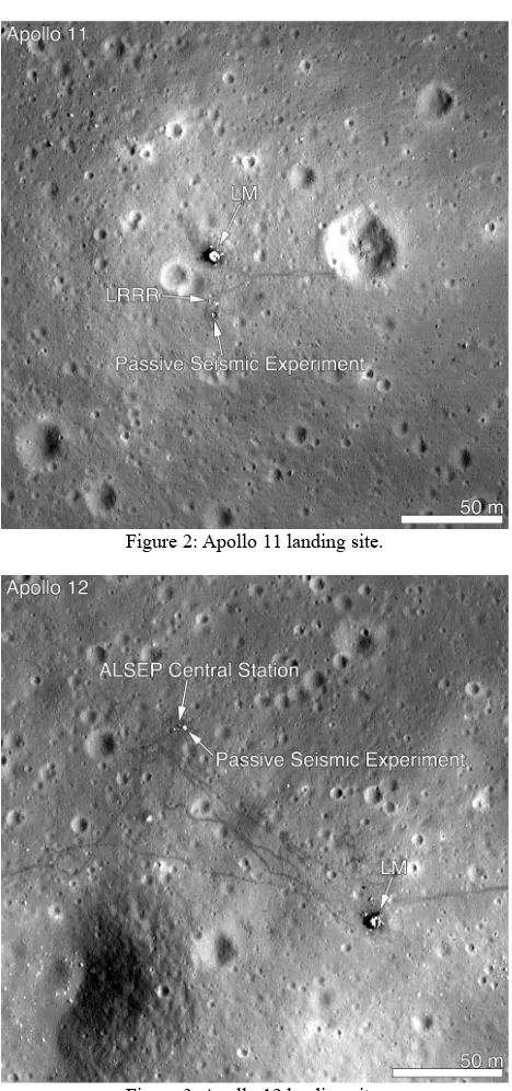
Figure 2: Apollo 11 landing site.
Figure 3: Apollo 12 landing site. International Archives of the Photogrammetry, Remote Sensing and Spatial Information Sciences, Volume XXXIX-B4, 2012
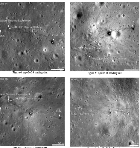
Figure 4: Apollo 14 landing site.
Figure 5: Apollo 15 landing site.
Figure 6: Apollo 16 landing site.
Figure 7: Apollo 17 landing site. International Archives of the Photogrammetry, Remote Sensing and Spatial Information Sciences, Volume XXXIX-B4, 2012