* Corresponding Author
ACCURACY ASPECTS OF UTILIZING RAW IMAGERY IN PHOTOGRAMMETRIC
MEASUREMENT
C. Stamatopoulos *, C.S. Fraser, S. Cronk
Department of Infrastructure Engineering, University of Melbourne, Victoria 3010, Australia [email protected], [email protected], [email protected]
Commission V, WG V/5
KEY WORDS: RAW Imagery, Photogrammetric Accuracy, Image Formation, Demosaicing, Target Centroiding
ABSTRACT:
Implicit in the projective transformation between object and image space in photogrammetry is the requirement that measured coordinates of points in the digital images accurately represent true values within the image coordinate system. This means that the integrity of image point positions has to be retained throughout the in-camera image preprocessing stage. However, the process of image formation and formatting for storage can impact upon image point position and it is imperative for subsequent photogrammetric measurement that image perturbations due to both sensor non-linearities and digital image file creation be fully described, modelled and mitigated to the maximum extent possible. Given that the integrity of image geometry is such an important factor in the optimisation of measurement accuracy in close-range photogrammetry, investigations into digital image formation are warranted. This paper describes such an investigation and it reports the development of a preprocessing approach for RAW imagery than can yield significant photogrammetric accuracy improvements over those obtained with JPEG imagery.
1. INTRODUCTION
When cameras record an image, a number of data processing functions are performed in order to provide a viewable image to the user. Every digital camera has a microprocessor that, apart
from controlling the camera’s generic functions, is specially designed to perform image processing tasks. In fact, many new features incorporated in cameras over recent years are improvements achieved by constant enhancements in the in-built image processor. These include corrections for sensor non-linearities and non-uniformities, auto-focus, white balance adjustment, colour interpolation, colour correction, compression and various other optimisations. Additionally, a final processing step is required to store the image in one of the commonly used formats, e.g. JPEG, and this can also be considered a data processing function.
Modern digital cameras and image file formats are certainly not designed with photogrammetry in mind, since the automatic implementation of such correction procedures can introduce small perturbations into the image coordinates. While such perturbations are negligible for low-to-medium accuracy applications, their impact is quite significant for higher accuracy measurement tasks such as industrial metrology or engineering-type measurements. Digital SLR cameras are invariably employed in such applications. An advantage of many digital SLR cameras is that they can save the unprocessed pixel values, which makes it possible to design and enforce a more
‘photogrammetrically suitable' workflow.
Images containing unprocessed pixels are commonly referred to as RAW images. When the camera stores a RAW image, it is saved as it was captured by the sensor and is the equivalent of a negative in film photography, since it contains the values just after the analog-to-digital (A/D) conversion, without any of the camera processing enhancements applied. In RAW format, the
pixels are represented in the bit-depth that is supported and recorded by the camera sensor, e.g. 10-, 12-, 14- or even 16-bits for newer sensors. This allows for the usage of the camera’s maximum metric potential, because it circumvents limitations caused by storing imagery in the commonly used JPEG format and also by ensuring that the full dynamic range of colour information is preserved.
In this paper, a review of camera sensors is given in order to provide a basis for discussion of the process of capturing, forming and storing an image. The purpose is to discuss both the metric aspects of the image formation pipeline that may affect any photogrammetric processing, and any drawbacks that are associated with the use of RAW imagery. Finally, a proposed process that aims to exploit the benefits of RAW imagery while minimizing shortcomings is presented. The typically used JPEG format along with the RAW format and the proposed methodology are then compared in real-world test networks. The resulting difference in attainable accuracy of 3D object space coordinate determination is illustrated through this experimental evaluation, and this highlights the advantages of the proposed methodology, which achieves similar results with the RAW imagery.
2. CAMERA SENSORS
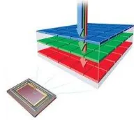
A colour image requires at least three colour samples at each location. Computer images typically use red (R), green (G), and blue (B) for representation of true-colour. One approach is to use beam-splitters (Parulski & Spaulding, 2003) along the optical path to project the image onto three separate sensors as illustrated in Figure 1a. Using a colour filter in front of each sensor, three full-channel colour images are obtained. This is a costly approach as it requires three sensors and moreover the relative positions and orientation of these sensors need to be
accurately established for photogrammetric applications. To minimize cost and size, most commercial digital cameras acquire imagery using a single electronic sensor overlaid with a colour filter array (CFA), as shown in Figure 1b, such that each pixel only samples one of the three primary colours.
a. Beam-splitter based b. CFA based
Figure 1. RGB imaging sensors
The most commonly used CFA pattern is the Bayer array which is composed of green pixels on a quincunx grid, and the red and blue pixels on rectangular grids, as shown in Figure 1b. The result is an image where 50% of the pixels are green, 25% red and 25% blue. Alternative patterns have also been used, for example a cyan, magenta, yellow and green pattern (CMYG). To restore a full-colour image from Bayer samples, the two missing colour values at each pixel need to be estimated from the neighbouring samples. This process is commonly known as CFA demosaicing or interpolation and it is one of the most important components of the colour image generation pipeline. For CFA-based cameras, an anti-aliasing (AA) filter is also placed in front of the sensor. The AA filter basically removes the frequencies in the image that are higher than the limits for the Bayer filter cell size, in other words, it blurs the details that are finer than the Bayer filter itself, with the purpose of reducing the Moire-like image artefacts caused by demosaicing. Despite the increased popularity of the sensors that record only one colour at each pixel location, sensors that are able to record complete RGB colour information in every pixel have become more accessible over the last decade. The Foveon X3, shown in Figure 2, is a unique sensor that supports an alternative approach to capture full colour information. For Foveon sensors, a different type of interpolation is required because the colours are not well separated. Interpolation is required in order to enhance colour and suppress noise.
Figure 2. A schematic of the Foveon X3 sensor
This paper is focused on Bayer RGB-based cameras, since they are nowadays the most commonly used. Nonetheless, the procedures explained are quite similar when different sensor types are employed.
3. IMAGE CREATION PROCESS
The imaging process is usually modelled as a linear process between the light radiance arriving at the camera and the pixel intensities produced by the sensor. In a CCD / CMOS camera, there is a rectangular grid of electron-collection sites laid over a silicon wafer to record the amount of light energy reaching each of the pixels. The electron count recorded in each cell of the sensor is converted to a numerical value with the help of the A/D converter. The RAW image is the product of this process where all the captured information is saved without any of the in-camera enhancements applied.
Outputting pixel values to any other digital file format involves additional processing of the RAW data. The preprocessing steps, along with a basic explanation of their purpose, are listed below in sequential order:
1. Black point subtraction:
In the total absence of light, the sensor returns greater than zero intensity values. If these values are not subtracted from the RAW data, the resulting images will look dull and black will not appear as black.
2. Bad pixel removal:
Almost every digital camera has a few dead pixels present in the sensor. Some cameras and software calculate pixel values by interpolation from neighbouring pixels.
3. Dark frame, bias subtraction & flat-field correction : Corrections applied to the image in order to reduce the noise introduced by the imaging sensor, amplifier and differing pixel sensitivity.
4. Green channel equilibrium correction:
This step aims to match the differences of the values of the green pixels in the blue/green rows with the green pixels in the red/green rows.
5. De-noising:
Commonly used in order to improve the brightness or colour information produced by the camera imaging sensor. Due to the various error sources, no sensor can provide perfect data and image sensors are no exception. 6. Colour scaling:
In order to provide good colour reproduction, all digital cameras include a white balance operation. White balance requires adjusting the RGB signal levels provided by the image sensor to correct for the colour temperature of the light source used to illuminate the scene.
7. Bayer interpolation:
Aims to create a fully populated RGB image for CFA sensors by interpolating missing colour information. 8. Image sharpening:
One process often used by digital cameras includes edge sharpening. The algorithms that are used in the Bayer interpolation differ in their ability to both produce clean edges and handle the level of noise. Additionally, image sharpening is used to correct image blur caused by the lens, optical anti-aliasing filter and the sensor's aperture, as well as to provide a subjectively sharper image that will be more pleasing to the eye.
9. Colourspace conversion:
A colourspace is an abstract mathematical model describing the way colours can be represented as tuples of numbers, typically as three colour components. Every device has its own description of colour, based either on what the manufacturer of the device thinks it should be, or on the technical limitations of the device, and rarely, if ever, do they match each other in terms of numerical values.
10. Gamma correction:
Gamma correction controls the overall brightness of an image. Images that are not properly corrected will look washed out. Gamma correction is important in displaying an image accurately.
11. Digital image format:
In order to save the image to a hard disk, a file format is required. JPEG is the most commonly used, however this lossy compression technique results in a loss of pixel intensity information.
It is evident that all these procedures modify the RAW pixel values to some extent. Further information on each of the eleven steps, as well as the effect they have on the metric integrity of the image can be found in Stamatopoulos (2011). When processing is performed in the camera, many choices are made by default and more importantly, there is often no option to omit certain steps. Unfortunately, this is not optimal from a photogrammetric standpoint, where access to unprocessed pixel values is preferable.
4. RAW IMAGERY
Under normal circumstances, image measurement in photogrammetry requires sharp and vivid images for the accurate selection of feature points. This requirement, however, is not universal. For example, in high-precision industrial photogrammetry the scene being imaged tends to be more structured as the measurement process most often relies on the use of retro-reflective targets and thus the need for ‘optimal’ true-colour imagery diminishes. As a result, the most significant operation is the precise recognition and identification of the targets. Ideally, an image of a retro-reflective target would consist of a black background (pixel brightness values close to the minimum possible value) and bright circular or elliptical white blobs (pixel brightness values close to highest possible value). The identification of such targets is then reduced to calculating the intensity differences between neighbouring pixels. Thus, the use of RAW imagery is certainly feasible but its need is limited to specific applications.
Working with RAW imagery, though, does not come without problems. It is often difficult to read the actual sensor data from RAW image files as most camera manufactures do not provide the specifications for their proprietary file implementation, and the data in the image file is also often encrypted. Nonetheless, an open-source project, named ‘dcraw’, can be used to gain access to the majority of RAW proprietary file formats. Various commercial software packages can also read RAW image files, but are sometimes limited in the information that can be extracted from the metadata due to licensing issues. Additionally, their procedure follows closely the in-camera processing and as a result the decoded RAW image files will be subjected to similar modifications in the original RAW pixel values.
It should be noted again that RAW files do not provide a true-colour image; instead, every pixel holds information only for a specific channel. Taking care of pixel gaps is the most significant task in scanning the images for retro-reflective targets, especially when the scanning algorithm incorporates intensity-weighted centroiding. Centroiding performance is optimal only when the green channel is used, since the Red and Blue channels each occupy only 25% of the image. Proper identification of targets for the Red and Blue channels is often precluded due to the lack of pixel information for subsequent rows. An important aspect of this step is that prior knowledge of
the CFA array is needed so that the colour of each pixel is known. For example, there are four different variations of a Bayer RGB CFA array, the top-left corner (2 x 2 pixels) for each is shown in Figure 3. Fortunately, knowledge of the CFA array of virtually every SLR sensor on the market is available
from ‘dcraw’.
5. PROPOSED METHODOLOGY
In spite of the practical inconvenience associated with processing and application of RAW imagery, procedures that exploit the metric advantages of this format can be developed. By using dcraw, it is possible to decrypt a RAW file and create a true-colour image. Due to dcraw's open-source nature, it can be modified to accommodate photogrammetric needs. This can be accomplished by changing the actual process of the image creation by removing every step that can possibly modify the acquired RAW values. Evidently, the only step that is necessary is the CFA interpolation for the creation of a full RGB image. Another advantage of this procedure is that due to the creation of full colour RGB images, they can be used for all photogrammetric applications. Moreover, what is beneficial about this approach is that sensors employing alternative CFA patterns using four different channels, e.g. CMYG, can now benefit from the use of RAW imagery.
5.1 Demosaicing algorithms
For the interpolated RAW files, a demosaicing algorithm is needed in order to interpolate the missing colour information. Careful selection of the demosaicing algorithm is required as it is an important aspect of full colour image creation. The in-camera interpolation algorithm is a compromise between quality of output and the time it takes to convert the RAW image into the desired format. The whole process is performed using a limited amount of memory, and it has to be fast enough to eliminate noticeable camera lag, while providing acceptable results for all images. Such a process is not optimal for photogrammetry because it results in accuracy loss in the intensity information due to the interpolation process. However, if the conversion takes place in the computer after the imagery has been downloaded, there is no real concern in performing less efficient post-processing that employs more sophisticated algorithms. Additionally, a variety of different algorithms can be tested and evaluated with the purpose of finding the most suitable for a particular set of images.
Dcraw supports four types of interpolation: 1. Bilinear
2. Interpolation using a threshold-based Variable Number of Gradients (VNG) (Chang et al., 1999)
3. Patterned Pixel Grouping (PPG)
4. Adaptive Homogeneity Directed demosaicing (AHD) (Hirakawa & Parks, 2003)
A review of the literature on demosaicing algorithms revealed various newer algorithms that could possibly perform better than these four. Seven additional demosaicing methods were therefore also implemented for testing in this investigation:
1. AHD interpolation with built-in anti-aliasing, developed by Lee (2009a)
R G
G B
G R
B G
B G
G R
G B
R G
Figure 3. The four possible variations of the Bayer RGB CFA
2. Colour demosaicing via directional Linear Minimum Mean Square-error Estimation (LMMSE) (Zhang & Wu, 2005), developed by Martinec (2010)
3. Colour demosaicing using Variance of Colour Differences (VCD) (Chung & Chan, 2006), developed by Lee (2009b)
4. Adaptive Filtering for colour filter array demosaicing (AFD) (Lian et al., 2007), developed by Lee (2010) 5. Combination of AHD and VCD, developed by Lee (2009b)
6. DCB, created and developed by Góźdź (2010) 7. Aliasing Minimization and Zipper Elimination (AMaZE), created and developed by by Martinec & Lee (2010)
Furthermore, for VCD and DCB, a post-demosaicing refinement step was also implemented. For the VCD algorithm, the refinement was based on the Enhanced Effective Colour Interpolation (EECI) algorithm (Chang & Tan, 2005), which was developed by Lee (2009b).
6. EXPERIMENTAL EVALUATION
In order to test the use of RAW image files in photogrammetry, access to the RAW data values of the sensor is needed. As dcraw is a standalone application, an equivalent C++ library version of this software, named LibRaw (LibRaw, 2011), was selected for the evaluation. The use of a library leads to easier implementation within Australis (Photometrix, 2012), the testing software platform used. LibRaw provides an application programming interface (API) to its internal functions which in turn makes it possible to gain RAW image support. For the proposed methodology, modifications to the source code were applied in order to ensure that no image preprocessing steps would alter the original sensor values, except for the CFA interpolation. The adapted demosaicing algorithms that were implemented and incorporated by the author into LibRaw were subsequently accepted and are now publicly available as a part of the LibRaw library (LibRaw, 2011).
The principal aim of the experimental program conducted was to examine the extent of variation in the mean positional standard error of object target point coordinates which accompany perturbations in the positioning of the centroid of the retro-reflective targets in a typical close-range photogrammetric network adjustment. A Nikon D200 camera was used to capture both JPEG and RAW images of a typical convergent, multi-image network. This allowed for the direct comparison of JPEG, RAW and various other datasets that were created by the use of different demosaicing algorithms.
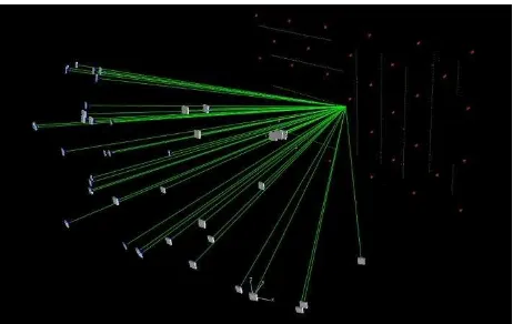
To achieve the experimental aims, a total of 43 photogrammetric adjustments of the same network were computed. The experimental test network adopted was not atypical of an imaging geometry that might be employed in an engineering or industrial photogrammetric survey. Figure 4 illustrates the geometry of the network, which comprised 42 images.
The recorded images were taken with different kappa rotations at each station, with each rotation being either , or . A total of 899 3D targeted points were present in the scene, these comprised 34 coded (each with 8 targets) and 627 single targets. A Tokina 18mm fixed focal length lens was used for the photography. It should be noted that the resulting RAW imagery from a Nikon D200 has a bit depth of 12-bits. The
processing of the datasets was performed in Australis, where a 10-parameter camera self-calibration model was used.
Figure 4. Object target array and camera configuration for the dataset taken with the Nikon D200
For all datasets, each of the RGB channels was used separately for the scanning and centroiding of the retro-reflective targets. Firstly, the Green channel results are presented, as it is the channel with most information and thus is expected to produce the most accurate results. The evaluation of the Red and Blue channels follows later on. It should be noted that the use of the Red and Blue channels is mainly applicable in special cases, such as where colour coded targets are employed, or for applications such as modelling chromatic aberration (Luhmann et al., 2006).
6.1 Green Channel
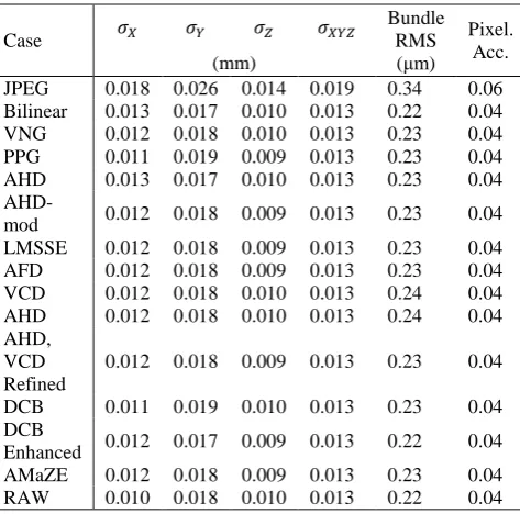
Table 1 lists the magnitude of the positional standard errors , , along each axis, as well as the mean positional standard error for the Green channel. The first column presents the different demosaicing algorithms used for both the JPEG and RAW datasets. The sixth column presents the RMSE value of the xy image coordinate residuals and the last column shows the estimated image measurement accuracy, in pixels. Generally, all the examined cases (except for the JPEG datasets) present little or no variations in the RMSE of the xy residuals, with the Bilinear, DCB-Enhanced, and the RAW having the lowest values. As regards the mean positional standard error among the demosaicing algorithms, the differences were not of a significant magnitude. The Green channel occupies 50% of the sensor size and thus even the simplest Bilinear algorithm provided reasonable results. However, even though a straightforward algorithm such as Bilinear interpolation can provide good results, in the experiment performed it was seen that it had a large number of rejected 2D image points compared to the other datasets, which could be related to the demosaicing process. The best accuracy of 0.0127mm was provided by the RAW and DCB Enhanced demosaicing algorithm that presented the lowest RMSE of the xy residuals. The AFD, AMaZE and LMSSE algorithms followed, with an accuracy of approximately 0.013mm, proving that they are among the current state-of-the-art demosaicing algorithms that can be used for photogrammetric purposes. The use of the proposed method provides an approximate 30% accuracy increase over the Green JPEG channel. It should be noted that the JPEG dataset presented two false positive target recognitions that were not presented in any of the other datasets. As expected, the higher dynamic range provided by the RAW imagery allows for better recognition results. This can be invaluable in cases where
photogrammetric measurements are not controlled to the same channel. Table 2 shows the accuracy of the same JPEG dataset with the different centroiding procedure. Overall accuracy was increased by 14% compared to that obtained using only the green channel. The DCB Enhanced dataset presents an approximately 24% increase in accuracy over the JPEG case.
Case Table 2. Estimates of mean positional standard error for JPEG dataset using all channels for centroiding.
6.2 Red channel
Table 3 presents the results of the datasets for the Red channel, in the same format as for Table 1. As initially foreseen, a substantial variation is present in the mean positional standard errors for each demosaicing case. The RMSE of image coordinate residuals from the bundle adjustment fluctuates from 0.24 to 0.54μm with the AFD, LMMSE and VNG having the lowest values.
Also as expected, the cases with the lowest RMSE values also present the most accurate referencing of the image points, which consequently leads to the highest mean positional accuracies in the object space coordinates. The AFD demosaicing demonstrates the highest accuracy of 0.0136mm, followed by LMSSE with 0.014mm and VNG with 0.015mm. The remaining demosaicing algorithms present accuracies varying
from 0.018-0.023mm. The JPEG dataset has the lowest accuracy of 0.032mm, and similarly to the green JPEG dataset, it gave two false positive target recognitions.
Despite the Red channel occupying only the 25% of the image sensor, some algorithms succeeded in producing accuracy close to that achieved by the Green channel. Compared to these datasets, the JPEG case presented an exceptionally large number of rejected 2D points. The use of interpolated RAW data showed at minimum an approximately 28% increase achieved by the modified AHD algorithm. The highest accuracy was produced by the AFD demosaicing, which showed a 57% Table 3. Estimates of the mean positional standard errors for the Red channel, for different demosaicing algorithms
6.3 Blue Channel
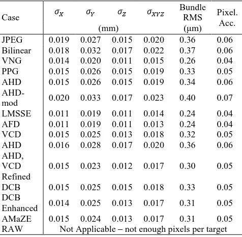
The Blue channel produced similar results to the Red channel, as can be seen from Table 4. In general, the datasets show a big variation in the RMSE of the xy residuals with the values fluctuating from 0.24 to 0.37μm.
Also similar to the Red channel, the AFD, LMSSE and VNG algorithms presented the lowest RMS values and consequently indicated the highest mean positional accuracy. More specifically, the AFD presented an overall accuracy of 0.0134mm and the LMSSE along with the VNG follow with 0.0138mm and 0.0147mm, respectively. Most of the remaining algorithms yielded accuracies ranging from 0.017-0.019mm, with the exception of the Bilinear and AHD-mod algorithms. The AFD, LMSSE and VNG algorithms also produced accuracy levels close to those obtained from the Green channel. When precision of the photogrammetric network. This was verified by the experimental program performed. The proposed approach
Case Table 1. Estimates of the mean positional standard errors for the Green channel, for different demosaicing algorithms
employing RAW imagery produces significantly higher mean positional accuracy than is achieved using JPEG imagery. It was also observed with the Green channel that, with the lack of a preprocessing stage, even the simplest Bilinear algorithm was able to provide very accuracte results. This illustrates the intrinsic importance of the proposed methodology, which has largely been ignored until now.
Case
Bundle RMS (μm)
Pixel. Acc. (mm)
JPEG 0.019 0.027 0.015 0.020 0.36 0.06 Bilinear 0.018 0.032 0.017 0.022 0.37 0.06 VNG 0.014 0.020 0.011 0.015 0.26 0.04 PPG 0.015 0.026 0.015 0.019 0.33 0.05 AHD 0.015 0.026 0.015 0.019 0.34 0.06
AHD-mod 0.020 0.033 0.017 0.023 0.40 0.07 LMSSE 0.011 0.019 0.011 0.014 0.24 0.04 AFD 0.011 0.019 0.011 0.013 0.24 0.04 VCD 0.015 0.025 0.013 0.018 0.32 0.05 AHD 0.016 0.028 0.017 0.020 0.36 0.06 AHD,
VCD Refined
0.015 0.023 0.012 0.017 0.30 0.05 DCB 0.015 0.025 0.015 0.018 0.33 0.05 DCB
Enhanced 0.014 0.025 0.013 0.017 0.31 0.05 AMaZE 0.015 0.024 0.013 0.017 0.31 0.05 RAW Not Applicable – not enough pixels per target Table 4. Estimates of the mean positional standard errors for Blue channel.
The results of the investigation confirm the theoretical relationship between each channel and the corresponding photogrammetric accuracy. Indisputably, the Green channel is the most accurate, as it demonstrates less variation in the obtained accuracies among the examined cases. This is because the Green channel occupies half the image, vs. 25% for both Red and Blue. The Blue channel results show that it is more accurate than the Red channel by a small margin. It is important to note that improved results are anticipated with newer cameras that are able to record colour information with dynamic ranges of 14- or 16-bits, or even higher.
The current state-of-the-art algorithms were expected to perform better for the Red and Blue channels. The image demosaicing process, however, does not aim for optimal results in photogrammetry, but instead is aimed to provide the most visually pleasing imagery for display. Further knowledge of the exact semantics of colour interpolation and reproduction is required in order to understand why each algorithm performs in a specific manner.
7. CONCLUSSION
The results show that simply by taking advantage of the
camera’s higher dynamic range and removing the preprocessing stage/s, all tested demosaicing algorithms performed better than the standard in-camera JPEG image formation. Additionally, to quantify the error introduced by the off-line demosaicing algorithms, a comparison against the non-demosaiced RAW imagery was carried out, with the results indicating the absence of any significant error. The proposed off-camera RAW image processing approach is able to provide an increase in
photogrammetric accuracy of up to 30% when compared to the use of in-camera preprocessed JPEG imagery. It is important to note that even better results can be anticipated with newer cameras that are able to record information with a higher dynamic range than the 12-bit images employed in this case. What is also appealing about the approach developed is its simplicity, since the required changes to photogrammetric data processing software systems are minor.
8. REFERENCES
Chang, E., Cheung, S. & Pan, D., 1999. Color filter array recovery using a threshold-based variable number of gradients. In: Proceedings of SPIE, vol. 3650, 36.
Chang, L. & Tan, Y., 2005. Effective use of spatial and spectral correlations for color filter array demosaicking. Consumer Electronics, IEEE Transactions, Vol. 50, pp. 355 - 365. Chung, K. & Chan, Y., 2006. Color demosaicing using variance of color differences. In: Image Processing, IEEE Transactions, Vol. 15, pp. 2944 - 2955.
Góźdź, J. & Rodriguez, L.S., 2010. FBDD denoising algorithm. http://www.linuxphoto.org/html/fbdd.html (22 Mar. 2011).
Hirakawa, K. & Parks, T., 2003. Adaptive homogeneity directed demosaicing algorithm. In: Image Processing, IEEE Transactions, Vol. 3.
Lee, P., 2009a. AHD modified algorithm. http://sites.google.com/site/demosaicalgorithms/modified-dcraw (22 Mar. 2011).
Lee, P., 2009b. VCD demosaicing algorithm. http://sites.google.com/site/demosaicalgorithms/modified-dcraw (22 Mar. 2011).
Lee, P., 2010. AFD demosaicing algorithm. http://www.rawtherapee.com/ (22 Mar. 2011).
Lian, N., Chang, L., Tan, Y. & Zagorodnov, V., 2007. Adaptive filtering for color filter array demosaicking. In: IEEE Transactions on Image Processing, Vol. 16, pp. 2515 - 2525. LibRaw, 2011. Libraw decoding/processing library. http://www.libraw.org/ (22 Mar. 2011).
Luhmann, T., Hastedt, H. & Tecklenburg, W., 2006. Modelling of chromatic aberration for high precision photogrammetry. In: ISPRS Symposium Commission V, Dresden, September. Martinec, E., 2010. LMSSE demosaicing algorithm. http://www.rawtherapee.com/ (22 Mar. 2011).
Martinec, E. & Lee, P., 2010. AMAZE demosaicing algorithm. http://www.rawtherapee.com/ (22 Mar. 2011).
Parulski, K. & Spaulding, K., 2003. Color image processing for digital cameras. Digital Color Imaging Handbook, pp. 728 - 757.
Photometrix, 2012.
http://www.photometrix.com.au (19/03/2012).
Stamatopoulos, C., 2011. Orientation and calibration of long focal length cameras in digital close-range photogrammetry. Ph.D. thesis, The University of Melbourne.
Zhang, L. & Wu, X., 2005. Color demosaicking via directional linear minimum mean square-error estimation. In: Image Processing, IEEE Transactions, Vol. 14, pp. 2167 - 2178.