AIRBORNE LINEAR ARRAY IMAGE GEOMETRIC RECTIFICATION METHOD
BASED ON UNEQUAL SEGMENTATION
J.M.Li a, b,*, C.R.Li a, M.Zhou a, J.Hu a, C.M.Yang c
a Key Laboratory of Quantitative Remote Sensing Information Technology, Academy of Opto-Electronics, Chinese Academy of Sciences, China - (jmli, crli, zhoumei, jhu)@aoe.ac.cn
b University of Chinese Academy of Sciences, China
c Software Center, Bank of China, China - [email protected]
Commission I, WG I/4
KEY WORDS: Linear array image, Geometric rectification, Unequal segmentation, Dynamic programming, Straight line feature
ABSTRACT:
As the linear array sensor such as multispectral and hyperspectral sensor has great potential in disaster monitoring and geological survey, the quality of the image geometric rectification should be guaranteed. Different from the geometric rectification of airborne planar array images or multi linear array images, exterior orientation elements need to be determined for each scan line of single linear array images. Internal distortion persists after applying GPS/IMU data directly to geometrical rectification. Straight lines may be curving and jagged. Straight line feature -based geometrical rectification algorithm was applied to solve this problem, whereby the exterior orientation elements were fitted by piecewise polynomial and evaluated with the straight line feature as constraint. However, atmospheric turbulence during the flight is unstable, equal piecewise can hardly provide good fitting, resulting in limited precision improvement of geometric rectification or, in a worse case, the iteration cannot converge. To solve this problem, drawing on dynamic programming ideas, unequal segmentation of line feature-based geometric rectification method is developed. The angle elements fitting error is minimized to determine the optimum boundary. Then the exterior orientation elements of each segment are fitted and evaluated with the straight line feature as constraint. The result indicates that the algorithm is effective in improving the precision of geometric rectification.
* Corresponding author
1. INTRODUCTION
Airborne linear array pushbroom sensors are becoming increasingly of interest for multispectral and hyperspectral applications. The pushbroom images are obtained line by line with the time sequence. Each line is shot at the same moment with a central projection, so each line has its own exterior orientation elements. The geometric rectification of linear images is different from airborne planar array images or multi linear array images, because there are no geometric constraints among each scan line, and each line is independently acquired with a different exterior orientation, so a classic bundle adjustment is not realistic, owing to the huge number of unknowns. Usually, with the position and attitude data from the POS system (GPS/IMU) carried on the airborne platform, the geometric correction of linear array images can be achieved by the traditional collinearity equations Li, 2014, Mostafa et al., 2001, Wang et al., 2011 . In order to eliminate POS data errors, (Tuo et al., 2005) used POS data to coarse correct first, and then applied polynomial model based on the reference images for further correct. (Wang et al., 2013) presented a geometric correction method which can be used to correct the linear array image based on the bias matrix. These methods improve the absolute accuracy to some extent, but internal distortion is difficult to eliminate, especially for high-resolution images with high scanning frequency. The line feature along the direction of flight may still be some curved and serrated after geometric rectification.
Straight line feature-based geometrical rectification algorithm was applied to solve this problem (Lee et al., 2000), whereby the exterior orientation elements are fitted by piecewise polynomial and evaluated with the straight line feature as constraint. However, atmospheric turbulence during the flight is unstable, equal piecewise can hardly provide good fitting, resulting in limited precision improvement of geometric rectification or, in a worse case, the iteration cannot converge. To solve this problem, drawing on dynamic programming ideas, unequal segmentation of line feature-based geometric rectification method is developed.
2. UNEQUAL SEGMENTATION METHOD
2.1 Exterior orientation elements polynomial model
Each pushbroom linear array image line is central projection. The rigorous imaging model of the line array image is
1 1 1
,
,
Assumed exterior orientation elements are functions of time within a short time, time-variable piecewise polynomial model of exterior orientation elements can be established.
The piecewise polynomial model has been often used to model platform trajectories in the satellite pushbroom scanner with a stable orbit. Taking into account the aviation environment, changes in the line elements are relatively stable, and changes in the attitude angles are more intense. The sensor position elements X Ysi
,
si, Z
si are modelled as linear functions of time, and the sensor orientation elements
i,
i,
i are modelled as quadratic polynomial functions of time:si si0 si1
2.2 Airborne linear image unequal segmentation
The airborne linear image was divided into N segments. And the angle elements of each image segment were fitted, the fitting error is ei
1 i N
, while i is the number of segments. Sothe total error of all the segments is computed as follows:
2 function, and the objective function can be simplified as follows:
2 fitting error of segment No.i is:1 1
(
, ,
)
i i i i
e
E e e e (5)And the total error of the image could be simplified as follows:
1 2 1 2 3 segment can be written as:
1
1
1
1
S
i e ei,
i
min S
i ei,
ei
ei ei (8)Where Si1
ei1,ei
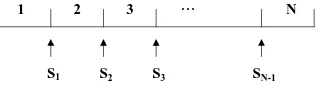
is the optimal solution of previous stage. It indicates that the left and right boundary of the segment No.i-1 is determined, and the right boundary of the segment No.i+No.i-1 is fixed.1 2 3 N
S1 S2 SN-1
…
S3
Figure 1. An example of segmentation
For example,the image is divided into N segment as Figure 1.
The optimal solution of each segment can be written as:
segment can be determined byS
i, and the right boundary of the last segment is the last line of the image.2.3 Processing Flow
In this paper, we use a frame orthophoto as reference image to get the control points and lines. The processing flow is as follows:
(1) Extract corresponding points and lines from the linear array image and reference image. Determine the maximum segment number that can be divided by the number of feature points and feature lines.
(2) According to the maximum segment number and the image length, divide the image into equal segments, and the boundary is used as the initial value. The right boundary of the last segment is the last line of the image.
(3) Calculate the right boundary
S
i of the ith segment. At this time, the left boundaryS
i1 of the ith segment is determined by the previous stage calculation, and the right boundaryS
i1 of the segment No.n+1 is fixed by the initial value. Search the optimal solution within the range of the initial position. When the right boundary of the ith segment locates in line k belonging to the search range, use quadratic polynomials to fit the angleelements of the segment No.i and No.i+1, and calculate the fitting error of all the points in the segments as follow:
2 2 2
The overall fitting error of the segment No.i is:
1
And the overall fitting error of the segment No.i+1 is:
1
(4) Determine the right boundary of all the segments using step (3), and calculate the overall fitting error of all the segments.
(5) The objective function is minimized by multistage searching, and the right boundary of each segment is determined by multi iteration, ultimately leading to the optimum segmentation.
3. GEOMETRIC RECTIFICATION BASED ON POINT AND LINE FEATURE
Using a frame orthophoto as reference image, the linear array image is corrected based on point and straight line feature method. First, corresponding points and straight lines are extracted from the linear array image and reference image. Then, the image is divided into several unequal segments using the method mentioned above. Then the exterior orientation elements of each segments are fitted by polynomial models. With the smoothing condition between adjacent segments as the constraint, a combined error equation based on point and straight line features can be formulated. At last, taking the straight line equation parameters, image coordinate of points in the straight line, image and object coordinate of feature points as the known numbers, and taking the parameters of the exterior orientation elements polynomial fitting model, the coordinate parameter of points in the straight line as the unknown numbers, solve the equation by adjustment, and get the exterior orientation elements of all the segments.
In this paper, the object space line can be determined by the reference image. We use the following form to express the line:
0 1
So, all the points belonging to the feature straight line of linear array image are in line with this formula. For each point in the straight line, we only need to estimate the parameter u.
When the linear array image is divided into segments, exterior orientation elements of each segment use different polynomial fit models. The smoothing condition is used to avoid alignment errors between the adjacent segments after geometric rectification. Since the exterior orientation is continuous, the value of the function computed from the polynomial in each of two neighbouring segment is equal at their boundary, and smooth.
The exterior orientation elements may dramatically change when flying in bad circumstances. In order to fit the elements accurately, the segment should have a very short time interval. Strong relativity in computing the exterior orientation elements is caused by the small image pieces. The method that line elements and angle elements are computed separately is used in this paper for the solution of exterior orientation.
4. EXPERIMENTAL RESULTS AND ANALYSIS
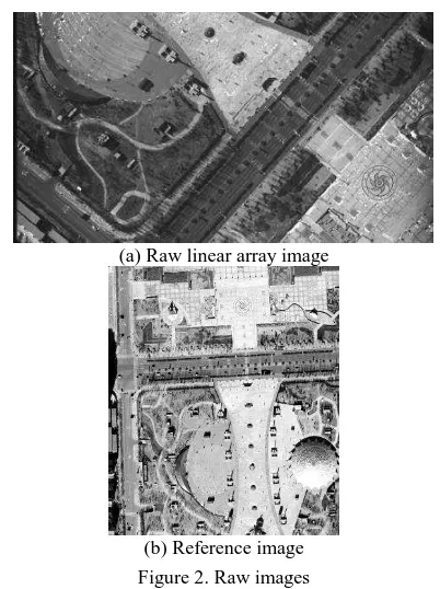
To validate efficiency of the method proposed, an experiment was carried out on the images acquired by a linear array sensor developed by the Academy of Opto-Electronics (AOE) on 2013, the flight area cover Neimenggu province of China. The image is 1825*1000 pixels with the GSD 0.2. The raw data is shown in Figure 2. Figure 2(a) is the raw linear array image. Figure 2(b) is the reference image with the GSD 0.2m.
(a) Raw linear array image
(b) Reference image
Figure 2. Raw images
Figure 3 is the geometric rectification result only using POS data. Due to the presence of aircraft platform dither, the zebra crossing has been significantly distorted after processing.
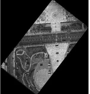
Using the unequal segmentation of line feature-based geometric rectification method, the image is automatically divided into 36 segments (see figure 4). Solving exterior orientation elements of each segments, and the geometric rectification result is shown
as figure 5. It’s easy to find out that curve and zigzag of straight line get better correction, our method could achieve better correction results than the traditional methods.
(a) Geometric rectification result
(b) Enlarged view of geometric correction result Figure 3. Geometric rectification result only using POS data
Figure 4. Unequal segment
(a) Geometric rectification result
(b) Enlarged view of geometric rectification result
Figure 5. Geometric rectification result based on unequal segmentation
Absolute precision evaluation is taken by check points. The evaluation results are shown in Table 1:
Check Points
using POS data only
Using line feature based on unequal segmentation
ΔX ΔY ΔX ΔY
1 0.49 0.83 0.45 0.58
2 0.26 0.32 0.01 0.10
3 0.53 0.54 0.49 0.03
… … … … …
11 0.40 0.42 0.24 0.10
12 0.95 0.26 0.01 0.25
RMS 0.46 0.46 0.23 0.21
Table 1. Absolute precision evaluation by check points(Unit: m)
Relative precision evaluation is also taken by check lines. Compute the coordinates (X, Y) of the point on the line which is closest to the point, the residuals for an estimated point along a check line are computed as relative precision. The evaluation results are shown in Table 2:
Check lines
using POS data only
Using line feature based on unequal segmentation ΔdRMS Δdmax ΔdRMS Δdmax
1 0.48 0.74 0.21 0.38
2 0.35 0.60 0.19 0.27
3 0.45 0.59 0.20 0.31
4 0.48 0.59 0.18 0.29
Average 0.44 0.63 0.20 0.31
Table 2. Relative precision evaluation by check lines (Unit: m)
From Table 1 and Table 2, we can see that compared with the rectification result only using POS data, the RMS of check points drops from 0.46m to 0.23m on x direction, and 0.46m to 0.21m on y direction. And the RMS of the distance by which the point deviates from the straight line drops from 0.44m to 0.2m.
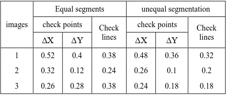
Three images chosen from different strips were used to verify the effect of unequal segmentation. The precision evaluation comparison of equal segments to unequal segments is shown in Table 3.
images
Equal segments unequal segmentation check points Check
lines
check points Check lines
ΔX ΔY ΔX ΔY
1 0.52 0.4 0.38 0.48 0.36 0.32 2 0.32 0.12 0.24 0.26 0.1 0.2 3 0.26 0.28 0.38 0.24 0.18 0.18 Table 3. Comparison of equal segments to unequal segments
(Unit: m)
From Table 3, we can see that compared with the equal segments method, the absolute precision of unequal segments method is improved by 16%, and the relative precision is improved by 28%.
5. CONCLUSIONS
At present, limited by the rigid geometric rectification technology, the airborne linear array image is not widely applied. As the request for multispectral and hyperspectral data is increased, linear array sensor is leading the development trend of remote sensing.
This paper developed an unequal segmentation of line feature-based geometric rectification method drawing on dynamic programming ideas. The experimental results indicate that the proposed algorithm is effective in improving the precision of geometric rectification in processing airborne high resolution linear array images.
ACKNOWLEDGEMENTS
The authors would like to thank for the project(Grant No.Y40B08A14Y) supported by The Innovation Program of Academy of Opto-Electronics(AOE), Chinese Academy of Science(CAS).
REFERENCES
Li, C.R., 2014. The Technology of unmanned aerial vehicle remote sensing system. Science Press, Beijing, pp. 164-186.
Mostafa, M., and Hutton, J., 2001. Digital image georeferencing from a multiple camera system by GPS/INS. ISPRS journal of photogrammetry and remote sensing. 56(1), pp. 1-12.
Wang, S.P., Zhu. J., and Zong, D.C, 2011. Geometrical rectification of hyperspectral image of GPS/INS. Beijing Surveying and Mapping, 2011(1), pp. 57-59.
Tuo, H.Y., and Liu,Y.C., 2005. A new coarse-to-fine rectification algorithm for airborne push-broom hyperspectral images. Pattern recognition letters, 26(11), pp. 1782-1791.
Wang, M., Hu, J., Zhou, M., Li, J.M., and Z. Zhang., 2013. Geometric correction of airborne linear array image based on bias matrix. In: International Archives of the Photogrammetry, Remote Sensing and Spatial Information Sciences, Hannover, Germany , Vol. XL-1/W1, pp.369-372.
Lee, C., Theiss, H.J., Bethel, S.J., and Mikhail, M.E., 2000. Rigorous mathematical modeling of airborne pushbroom imaging systems. Photogrammetric Engineering and Remote Sensing, 66(4), pp. 385-392.