Finite Element Simulation of Deep Drawing of
Steel - Aluminium Tailor - Welded Blanks
Agus Dwi Anggono
*, Waluyo Adi Siswanto
+ *Department of Mechanical Engineering
Universitas Muhammadiyah Surakarta, Jawa Tengah, Indonesia [email protected]
+
Faculty of Mechanical and Manufacturing Engineering Universiti Tun Hussein Onn Malaysia, Johor, Malaysia
Abstract—In the automotive and aerospace industries, the need for lightweight products is absolutely necessary. By combining between the strength and lightweight material usingTailor Welded Blank(TWB), the need can be Aluminium alloy thatare formed into single blank sheet.The purpose of this numerical study is to demonstrate that dissimilar strength Steel-Al TWB can be subjected to deep drawing operations successfully, using optimum process parameters in the Finite Element (FE) simulation.The simulation indicate that Steel-Al TWB can produce deep drawing components.
Key words - Sheet Metal Forming, Deep Drawing, Finite Element, Tailor Welded Blanks, Blank Holder, Steel-Aluminium sheet.
I. INTRODUCTION
A. Tailored Welded Blank
Tailored welded blank (TWB) is a relatively new blank material introduced in sheet metal forming. A TWB consists of two or more flat sheets of metal that are welded together before forming. An illustration of TWB is shown in Fig. 1. A combination of different material properties, thicknesses, and coatings can be welded to form a new blank material used for stamping automotive side frames, doors, pillars and rails [1,2].
Fig. 1 Illustration of TWB joining of two plates with different thicknesses.
The main advantage of using tailor welded blanks (TWB) is to have specific strength of parts,to reduce the weight and production cost. Automotive industry is one of the customers
of sheet metal components capitalizing on the advantages of TWB. There is a research focus on reducing the vehicle weight for performance reasons and fuel consumtions. Each 68 kg of weight reduction creates a 0.43 km/liter fuel efficiency improvement in the vehicle [3].
The manufacturing cost is become a critical issues when producing a mass production product. Material selection of the advanced lighter material is not always as the solution. It can be more expensive and can be approximately 80% of the final cost in sheet metal forming (SMF) [4].
Steel blank is commonly used in automotive industries due to the strength, weld ability and good formability.Aluminium alloys are potential materials for light weight components because of their formability, corrosion resistance and low density. Hence, the use of Steel-Aluminium TWB can be adopted to produce both lightweight and strength components.
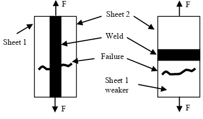
B. Failure in Tailored Welded Blank
There are two types of TWB failure in the tensile test and it may be occure in the forming processes [5]. Filure type 1 is caused by tensile load along the line direction due to the ductility on the weld area. Filure type 2 is occure on the weak material due to the tensile load perpendicular to the weld line, as shown in Fig. 2.
Fig. 2TWB failure mode in the tensile test.
A technique of welding possible to join steel and aluminium is friction stir welding technique. That is produce heat between tool and material and generate solid-state bonding between the base metal [6].In this forming analysis, the welding is assumed as perfect joining and the investigation is conducted only on the different properties of TWB.
In this paper, finite element results of deep drawing of Steel-Aluminium TWB are presented. The studies provide an insight on the formability of TWB which may be widely used in automotive and aircraft components in order to reduce weight.
II. SIMULATION OF DEEP DRAWING
A. Tester Models of 2D and 3D
In this analysis, the 2D tester model was adopted from Numisheet 1993 benchmark model, while the S-Rail model of benchmark problem 2 Numisheet 2008 was selected as the 3D model tester. Those models have a punch, die, binder and blank surface as shown in Fig. 3. The finite element software used in this simulation is Autoform.
Fig. 3 Model 2D of Numisheet 93 and S-rail 3D of Numisheet 2008
B. Material Properties of TWB
The strain hardening is modeled byanisotropic hardening rule which is widely adopted inpredicting purely elastic springback. Table 1 shows the material properties of thickness, frictioncoefficient, yield strength and rolling direction.
TABLE I MATERIAL PROPERTIES
Material type Steel DC05 Aluminium 5251-O
Thickness 1 mm 1 mm
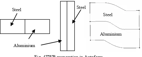
Rolling direction Paralel to x Paralel to x Friction coef 0.13 0.13 aluminium. It is important that Autoform does not specify the minimal thickness, but the mean thickness of the different blank are as tool setting. The TWB in Autoform can be described by divided single blank into two or more area then continued to the materials definition. The blank definition can be illustrated as in Fig. 4. Therefore the weld line type is open weld line.
C. Adaptive Meshing
The spatial discretization with finite elements of varying size is an important condition for the fast simulation of deep drawing. In Autoform, the refinement or de-refinement during forming is called adaptive mesh. There are three level refinement in Autoform and it can be costomized for more accurate analysis [7].
In this analysis, the blank is meshed by using adaptive mesh. Spatialdiscretization with finite elements of various
sizes is an important condition fora fast simulation of deep drawing processes of large and complex sheet formingparts, with the use of small elements in the zones with a strongly curved geometry.In terms of accuracy, rough, standard and fine mesh are selected in the simulation.
Fig. 4TWB preparation in Autoform
The adaptive refinement mesh type affects the results of analysis.In each time step of the simulation each triangle can be divided into smallersize. This refinement can be carried out recursively up to its maximum refinementlevel. If this refinement degree is not needed, then these smaller triangles arecombined again into one.The illustration of mesh refinement can be seen in Fig. 5. Increasing the density of mesh size or refinementmesh improves the accuracy of the result. Therefore, higher mesh density willincrease CPU time during the analysis [8].
Fig. 5 Adaptive mesh refinement in Autoform.
III. RESULTS AND DISCUSSION
A. Results of 2D Model
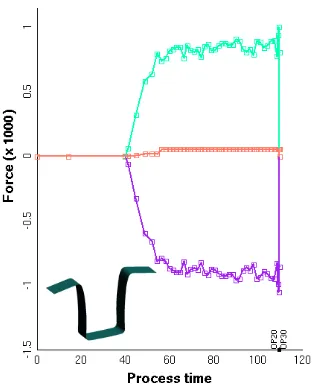
In the U-bending process, there is no wrinkling defect during forming, so its quality is evaluated from the aspects of cracking and springback. The punch is subjected to forces during drawing steel-aluminium TWB simulation. In the first stage, the punch force increase linearly as shown in Fig. 6.
The higher strength coefficient of steel blank sheets will need the higher force to deform the blank. As shown in the Fig. 6, steel-aluminium TWB has dominant effect on the punch force.
Fig. 7 is illustrate the springback result of steel-aluminium after U-bending. From the figure, it is clearly seen that the aluminium side deliver the higher springback compared to the steel side. Aluminium have a lower density than steel and flow faster during forming. That is for the weld orientation of
Fig. 6 Punch force during the process of U-bending.
B. Results of 3D Model
The springback simulation of S-rail 3D model are very sensitive to the finite element parameters such as element types, mesh sizes, material data, tools, drawbeads, lubrication and process definition.The blank parameters are sizes, shapes, thickness, rollingdirections, positions and material data. The material data include the hardeningvalues and choices of an appropriate yield surface. Geometric drawbeads arenecessary when the hardening and thinning material drawn by the drawbead intothe part geometry has a significant effect on springback, but in this analysis, there is no drawbead model in the forming simulation.
Fig. 8 shows the punch force during the forming process. The punch force is very high because the process applied blank holder force on the binder. By using the tailor model of TWB as shown in Fig. 4, the springback error of the S-rail model is not so different between the steel side and aluminium side as described in Fig. 9. By applying binder force during forming, the flow in of the blank can be controlled. Therefore the lower springback can be achieved.
Fig. 7 Springback result of steel-aluminium TWB in U-bending
Risk of split is potentially occur in the using of blank holder force and using lower density material such as
aluminium. In the steel-aluminium TWB, the risk of split is investigated after the trimming process. From the Fig. 10, the risk of split is arise on the aluminium side of the product. To minimize the risk of split, blank holder force is then reduce and lower punch speed. Risk of wrinkling is also occur in the aluminium side as shown in Fig. 11. Wrinkling is one of defect in the process of sheet metal forming which results from the compressive stress in the direction of membrane. There are also many factors which influence the wrinkling, such as thickness, material, friction, binder force and drawbead. Besides compressive stress, wrinkling is also controlled by the geometry of the sheet.
Fig. 8 Punch force during the process of S-rail 3D model.
Fig. 9 Springback result of steel-aluminium TWB in S-rail Aluminium
side Steel
side
Aluminium side
Steel side
Page 403 of 436
Fig. 10 Risk of split occure on the Aluminiun side.
Fig. 11 Risk of wrinkling occure on the Aluminiun side.
IV. CONCLUSIONS
The deep drawing simulations were successfully conducted by using steel-aluminium TWB both in 2D and 3D model. The results are show the trend of the possibility of furthering sheet metal forming by using combination steel and aluminium in single blank. In the Steel-aluminium TWB, aluminium is a weaker part subjected to higher plastic deformation and delivere higher springback.
ACKNOWLEDGMENT
The authors would like to thanks to Universitas Muhammadiyah Surakarta (UMS) and UniversitiTun Hussein Onn Malaysia (UTHM) forsupporting the software license.
REFERENCES
[1] A. A. Zadpoor, J. Sinke, R. Benedictue, Mechanics of tailor welded blans: An overview, Key Engineering Materials, 2007, Vol. 344, pp. 382. [2] www.twbcompany.com/Applications.html.
[3] Brooke , L. and H. Evans, Lighten Up!, Automotive Engineering International,March : 16 – 26, 2009.
[4] Natsumi , F. , K. Ikemoto , H. Sugiura , T. Yanagisawa , and K. Azuma, Laser WeldingTechnology for Joining Different Sheet Metals for One-Piece Stamping, JSAE Review, 1991, Vol. 12 ( 3 ), pp. 58 – 63 . [5] A. D. Anggono, T. W. B. Riyadi, Finite Element Simulation of The
Drawability of Tailor-Welded Blank, Applied Mechanics and Materials, Vol. 660, 2014, pp. 3-7.
[6] Chen CM, Kovacevic R. Joining of Al 6061 alloy to AISI 1018 steelby combined effects of fusion and solid state welding. Int J Mach ToolManu, 2004, vol. 44, pp.1205–1214.
[7] Autoform plus R2. AutoForm plus R2 Documentation. AutoForm engineering, 2010.
[8] W. A. Siswanto, A. D.Anggono, B Omar, and K.Jusoff, An Alternate Method to Springback Compensation for Sheet Metal Forming, The Scientific World Journal, 2014, Vol. 2014.
Risk of wrinkling