A STUDY ON THE CHARACTERISTIC OF
FOULING FACTOR OF A LABORATORY SCALE
SHELL AND TUBE HEAT EXCHANGER
Sulis Yulianto
*, Fadwah Maghfurah
*, Munzir Qadri
* *Department of Mechanical Engineering University of Muhammadiyah Jakarta, Jakarta, Indonesia
[email protected], [email protected], [email protected]
Abstract
- Heat exchangers have been commonly used
in industrial processes such as thermal power plant,
chemical process, air conditioner device, refrigerator,
even in some bigger energy processes like oil and gas.
The performance of a heat exchanger is not
permanently the same during daily and even
annually uses whereas one of the most common
causes is the fouling factor. In this research, the
performance of a laboratory scale heat exchanger
was observed by the inlet and outlet temperature of
hot oil and cold water fluids based on characteristic
of fouling factor. The flow rates were kept constant
at 0.72 m
3/hour for shell and 0.468 m
3/hour for tube.
The observation time was at 06.00 am, 12.00 am,
18.00 pm, 24.00 pm every day for six respective days.
The result shows that
Δ
Tm changes irregularly
during the observation while the fouling factor
increases regularly and decreases significantly by the
end of the observation.
Keywords: Heat exchanger, fouling factor, shell and
tube, characteristic.
I. INTRODUCTION
The designed heat exchanger of this first year is going to be operated for 23 days with no stop and the data of measurement is then taken. An analysis is then conducted based on the obtained data to study the performance characteristic of the designed heat exchanger.
II. EXPERIMENTAL METHOD
Method we use in this research is by analyzing the planned specification of heat exchanger design, the designed specification calculation so the proper specification can be obtained in numbers and transformed into a laboratory scale heat exchanger. The flowchart of this research is as follows.
Picture 1. Flowchart of research activities
III. DISCUSSION
In this research, determining the heat exchanger design specification was firstly conducted before calculation analysis of the laboratory scale shell and tube heat exchanger.
Picture 2. Heat exchanger assembly No
Yes Yes
No Start
Pumping system specification plan
The result analysis of the heat exchanger plan
The making of the heat exchager
Noting measurement data
Analysis and discussion
Writing report No
Finish
Page 375 of 436
Picture 3. The unit of heat exchanger system Tabel 1. Designed specification of shell and tube
heat exchanger
IV. RESULT ANALYSIS
The result analysis is based on 23 months of experiment data. The 23 months here is a scaled time of 23 days wherein one day is scaled to be equal to one month. This scaling method is considered to be important in order to have a longer simulation period of the heat exchanger experiment and give a better chance to observe the performance characteristic.
Calculation of heat flow rate absorbed by the cooling water which can be done by using the equation below,
Qc = mc cst x Cpc x (Tco-Tci) (1)
Calculation of heat flow rate released by the hot fluid,
Qh = mh cst x Cph x (Thi−Tho) (2)
Calculation of Log mean temperature difference of both fluids,
∆Tm = ∆T1−∆T2
ln ∆T1/ ∆T2 (3)
Calculation of overall heat transfer coefficient (U),
U = Qcst
Acst . ∆Tm (4)
Calculation of fouling factor during operation which can be done by using the equation below,
ΣRf = 1
Uf−
1
Uc cst (5)
The results from above calculations are then converted into graphic charts before conducting performance predictions.
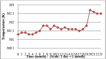
Picture 4. Charateristic of shell inlet temperature (Thi)
Picture 5. Characteristic of shell outlet temperature (Thi)
Picture 6. Characteristic of tube inlet temperature (Tci)
Picture 7. Characteristic of tube outlet temperature (Tco)
319.9
0 1 2 3 4 5 6 7 8 9 1011121314151617181920212223
T
0 1 2 3 4 5 6 7 8 9 1011121314151617181920212223
T
0 1 2 3 4 5 6 7 8 9 1011121314151617181920212223
T
0 1 2 3 4 5 6 7 8 9 1011121314151617181920212223
T Designed Specification of HE Unit
Tube diameter OD = 0,0127 mm Length of tube 0,6 m
Are of Heat Exchanger 0,88 m2
Shell incoming fluid mass flow rate (mh) 0,075 kg/s Tube incoming fluid mass flow rate (mc) 0,122 kg/s Tube incoming cold fluid temperature (Tci) 27OC/ 300 K
Tube outgoing cold fluid temperature (Tco) 37OC / 310 K
Shell incoming hot fluid temperature (Thi) 47 OC / 320 K
Thermal load (Q) 5100 Watt Overall heat transfer coefficient (U) 900 W/m2K
Heat exchanger effectiveness 61 %.
Page 376 of 436
Picture 8. Characteristic of Fouling Factor
Prediction of designed heat exchanger performance
Rf = Rf∗. (1−(e(−
Thus, in order to determine the time that the fouling takes (tc) then another calculation should be done by using the equation
tc = tm ln ( Rf∗
Rf∗− Rfm) (8)
so that the predicted time of the fouling formed in the system (tc) is 5.5 months of operation.
By using equation (6), we can predict how a fouling layer is formed in the system after 23 months of operation. The prediction can be seen in an asymptotic graphic data as an approximation result shown in Fig. 9. This result of predicted characteristic of deposit development is obtained after 23 months of operation.
Picture 9. Asymptotic graphic of fouling formed after 23 months
This heat exchanger is planned to operate at constant thermal load (Qcst) and be scheduled for cleaning as the mean
temperature difference of both fluids has reached 20% higher than the initial designed temperature of 7.6 K.
Qcst: ΔTmf operation time of this heat exchanger is planned to be as long as 23 months, then the characteristic value of fouling factor can be obtained by the time of cleaning interval period is reached. Equation (6) can be used to observe the fouling factor after 23 monnths of operation.
Picture 10. Prediction of cleaning interval
Overall heat transfer (Uf) of the designed heat exchanger can be determined by using equation (10).
ΔTmf =ΔTmc (1 + ( Uc . Rf∗) (10)
Uc . Rf∗ = (ΔTmf−1)
Uc =ΔTmf− 1
Rf∗
By obtaining overall heat transfer (Uc) of 3571.4 W/m2K and using the equation
A = Qc the results to observe characteristic of working fluids inside the system using data calculation and graphic.
Prediction of designed heat exchanger performance by fouling factor dan time function of conventional design
In order to find out the global coefficient of overall heat transfer (U) during (t) = 23 months, we can use equation (13).
U = ((1 picture about thermal characteristic of a heat exchanger designed by using conventional method. The results of performance prediction by cold fluid temperature and cold fluid mass flow rate of the cooling fluid can be seen on Picture 11 and picture 12, respectively.
Picture 11. Cold fluid temperature out
Picture 12. Mass flow rate of cooling fluid
V. CONCLUSIONS
Power for pumping fluid should be raised by stages or by using an additional equipment which is able to either automatically or conventionally control the speed of mass flow in the piping system.
REFERENCES
[1] Ramesh K. Sahah and Dusan P Sekulic 2003. Fundamentals of Heat ExchengerDesing. John Wiley & Son, INC. Hoboken, New Jersey.
[2] Ricahard. C. Byrne. 2000. Standard of the Turbular Excharnger Manufactures Association, standards of the Turbular Exchanger Manufacture Assocition, INC. New York,.
[3] Epstein, N. 1978. Fouling in Heat Exchangers, Heat Transfer Engineering, vol 6, New York,.
[4] Keith Escoe, A., Mechanical Design of Process Systems,
vol. 2, Gulf Pub. Company, Houston Texas, 1986.
[5] Soekardi. C. April 2001. Prediksi karakteristik termal sebuah penukar kalor dampak pemilihan faktor pengotoran konstan, Poros, 4 No 2, 141-150.
[6] Soekardi.C. April 2002. Implikasi Perancangan Sebuah penukar kalor dengan faktor Pengotoran dan fungsi waktu terhadap kinerjanya pada kondisi operasi beban thermal konstan, Poros, Vol. 5. NO. p. 129-137.
[7] Thurmarimurungan M. 2006. Performance Analysis of Shell and TubeHeat Exchanger Using Miscedle System. American Journal of Applied Sciences.
[8] Yulianto S. 2010. Analisa Perancangan Alat Pendingin Jenis Shell And Tube Dengan Cleaning Interval yang Bervariasi. Tesis Program Studi Teknik Mesin Universitas Pancasila.
0 1 2 3 4 5 6 7 8 9 1011121314151617181920212223