ISSN: 1693-6930
accredited by DGHE (DIKTI), Decree No: 51/Dikti/Kep/2010 91
Practical Control for Two-Mass Positioning Systems in
Presence of Saturation
Fitri Yakub*1, Andika Aji Wijaya2, Mustafa Al-ani3
1
Malaysia-Japan International Institute of Technology (MJIIT), Malaysia
2College of Engineering & Information (CEIT), Saudi Arabia 3
International Islamic University Malaysia (IIUM), Malaysia
e-mail: [email protected], [email protected], [email protected]
Abstrak
Sistem posisi presisi umumnya perlu pengendali yang baik untuk mendapatkan tangapan cepat, akurasi tinggi dan kokoh. Selain itu, kemudahan, kesederhanaan struktur desain pengendali dan kinerja gerakan cepat kendali sangat penting untuk aplikasi praktis. Untuk memenuhi persyaratan ini, nominal characteristic trajectory (NCT) dengan proportional integral (PI) dan notch filter (NF) sebagai kompensator diusulkan sebagai metode kendali praktis untuk sistem penentuan posisi PTP putar dua massa. Bagaimanapun, efek saturasi aktuator tidak dapat sepenuhnya dikompensasi karena penyelesaian integrator dengan parameter objek bervariasi. Makalah ini menyajikan suatu metode untuk lebih
meningkatkan pengendali nominal characteristic trajectory following (NCTF) dalam mengatasi
masalah penyelesaian integrator dengan mengadopsi skema PI anti-windup. Pendali NCTF perbaikan dievaluasi secara eksperimental menggunakan sistem penentuan posisi putar dua massa. Pengaruh parameter desain pada ketahanan NCTF perbaikan dengan pengendali integrator anti-windup dievaluasi dan dibandingkan dengan NCTF tanpa integrator anti-windup dan pengendali PI ekivalen. Hasil penelitian menunjukkan bahwa pengendali NCTF perbaikan dapat mengkompensasi efek integrator windup secara efektif.
Kata kunci: integrator windup, pengendali NCTF perbaikan, sistem dua massa, sistem posisi
Abstract
The precision positioning systems generally need a good controller to achieve a fast response, high accuracy and robustness. In addition, ease, simplicity of controller design structure and high motion control performance are very important for practical applications. For satisfying these requirements, nominal characteristic trajectory (NCT) with proportional integral (PI) and notch filter (NF) as a compensator has been proposed as a practical control method for two-mass rotary PTP positioning systems. However, the effect of the actuator saturation cannot be completely compensated due to integrator windup when the object parameter varies. This paper presents a method to further improve nominal characteristic trajectory following (NCTF) controller to overcome the problem of integrator windup by adopting PI anti-windup schemes. The improved NCTF controller is evaluated experimentally using two-mass rotary positioning systems. The effect of the design parameters on the robustness of the improved NCTF with windup integrator controller is evaluated and compared with NCTF without anti-windup integrator and the equivalent PID controller. The results show that the improved NCTF controller is effective to compensate the effect of integrator windup.
Keywords: improved NCTF controller, integrator windup, positioning systems, two-mass system
1. Introduction
Positioning Positioning systems play an important role in industrial engineering applications such as advanced manufacturing systems, semiconductor manufacturing systems and robot systems. Many effort to improve mechanisnm features of the systems for high positioning performance have prove to be costly. Basically, point-to-point (PTP) positioning systems are required to have fast response speed, high accuracy and robustness. However nonlineaarities like friction and saturation which exist in the positioning system may cause slow motion, steady state error and limit cycles.
by uncertainties due to variations of the lubrication condition or inertia while saturation effect comes from the source of the actuator or electronics power amplifier [1]. Therefore, the positioning systems are also required to have robustness to parameter variation.
Until now many types of controllers have been proposed and evaluated for positioning systems, for example the model following type controller such as controllers with disturbance observer [2], time optimal controllers [3], and sliding mode controllers [4]. These controllers will give good positioning performance in case of the designer have an exact model and value of its parameters. In general, advanced controllers like fuzzy logic controllers [5] and artificial neural network [6] tend to be complicated and required deep knowledge concerning with controller theory and design.
However in practical application, for engineers who are not expert in control theory design will face troublesome and time comsuming to determine exact model and parameter identification for the systems.
In two-mass system applications such as the rolling mill drive, the mechanical part of the drive has a very low natural resonant frequency because of the large roll inertia and the long shaft including the gear box and the spindle. Due to this, the finite but small elasticity of the shaft gets magnified and has a vibrational effect on the load position which may reduce positioning accuracy [7]. Therefore, the existing NCTF controller that has beed proposed in 2002 for one-mass rotary system can not be used directly in the case there is a flexible connection between elements of the positioning systems [8].
In order to overcome this problem, the improvement of nominal characteristic trajectory following (NCTF) controller has been proposed by authors as a practical controller for two-mass rotary positioning systems in [9]. It has been shown that, the improved NCTF control system has a good positioning performance and robustness. The improved NCTF controller is also effective to compensate the effect of the friction. However, the effect of actuator saturation cannot be completely compensated due to integrator windup when the object parameter varies [10].
In control system applications, all actuators have limitations, such as motors have limited speed. Therefore, if the actuator reaches the saturation limit, it will saturate. This saturation of the actuator may cause the integrator windup. The purpose of this chapter is to examine the effect of the integrator windup and describe a method to improve PI compensator of NCTF controller to overcome the degradation of the positioning performance due to integrator windup for two-mass rotary positioning systems. Firstly, the integrator windup problem and its background of anti-windup strategies and method are described in Section 2. Next, NCTF control concept and its controller design procedure are introduced in Section 3. Then, the design of the tracking anti-windup for improved PI compensator to overcoming the integrator windup is described in Section 4. Finally, the effect of saturation on positioning performance is evaluated and compared with NCTF without anti-windup integrator and equivalent PID controllers in term of positioning performance and its robustness in Section 5
.
2. Anti-windup Strategies
In applications of two-mass systems with the large range input of operations, it possibly happens that the control signal reaches the actuator limits. If this happens, the feedback of the controller saturates and the system runs as an open-loop system since the actuator will remain at its limit independently of the plant output as shown in Figure 1. If the controller contains integrator action, the error will be integrated and it will degrade the positioning performances. This means that the integral term in controller becomes very large. This problem is called windup problem. Then, the error must have opposite sign for certain period of time before things returned to normal [11].
(a) (b)
Figure 1. Integrator windup effect in control system: (a) Closed-loop, (b) Open-loop
There are three classical methods to avoid the integrator windup; condition integration, limited integrator and tracking anti-windup [12]. In the condition integrator method, the problem of integrator windup is solved by switching the integrator on and off depending on certain factors, such as the size of the control signal or the control error. In other words, it switches off the integrator when the control response is far from the steady state. Disadvantage of this method is that the controller may stack at the non-zero control error if the integrator term has a large value at the time of the switching off.
In the second method, the limited integrator will be accomplished by feeding the integrator output through a dead zone with a high gain, and the dead zone is used to reduce the integrator input. Third method is tracking anti-windup, which is applied when the control output reaches the actuator limits, the feedback signal is generated from the difference of the saturated and the unsaturated control signal and then, amplified by the gain, KT to reduce the integrator
input.
To illustrate this idea, the signal is zero when there is no saturation, thus, there is no effect on the normal condition, i.e. when the actuator does not saturated. However, when there is saturation, the signal will differ from zero, the normal feedback is broken and the feedback around the integrator is driven by this signal towards a value such that the integrator input becomes zero.
In NCTF controller for a two-mass system, there are two ways to avoid the integrator windup problem. First, replace PI by using another compensator, like FLC, and second, by designing anti-windup PI compensator from three methods described above. This paper discussed the second method
.
3. NCTF Control Concept
The structure of the NCTF control system is shown in Figure 2. The NCTF controller consists of a Nominal Characteristic Trajectory (NCT) and a compensator. The NCTF controller works under the following two assumptions [13]:
a) A DC or an AC servo motor is used as an actuator of the object. b) PTP positioning systems are discussed, so θr is constant and θr’ =0.
An exact modeling including friction and conscious identification processes is not required in the NCTF controller design. Since the DC motor is used as the actuator, the simplified object can be presented as the following fourth order system:
2
object response which does not include the vibration.
The objective of the NCTF controller is to make the object motion follow the NCT and end at the origin of the phase plane (e, e’). Signal up shown in Figure 2 represents the
object motion perfectly follows the NCT. The compensator is used to control the object so that the value of up, which is used as an input to the compensator, is zero.
Figure 2. Structure of NCTF control system for PTP positioning
The NCTF controller is designed based on a simple open-loop experiment of the object as follows [13]:
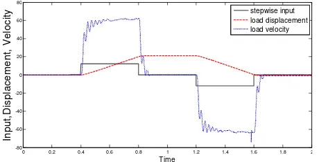
(a) Open-loop-drive the object with a stepwise input and measure the displacement and velocity responses of the object. In order to construct the NCT, a simple open-loop experiment has to be conducted. In the experiment, an actuator of the object is driven with a stepwise input and, displacement and velocity responses of the object are measured. Figure 3 shows the stepwise input, load velocity and load displacement responses of the object. In this case, the object vibrates due to its mechanical resonance. In order to eliminate the influence of the vibration on the NCT, the object response must be averaged.
0 0.2 0.4 0.6 0.8 1 1.2 1.4 1.6 1.8 2
-80 -60 -40 -20 0 20 40 60 80
Time
In
p
u
t,
D
is
p
la
c
e
m
e
n
t,
V
e
lo
c
it
y stepwise input
load displacement load velocity
Figure 3. Input and actual object response
the inclination near the origin, m and the maximum error rate, h relate with parameters of the dynamic object as follows [15]:
Figure 4. Construction of the NCT
(c) Design the compensator by using the NCT information.
The following PI and notch filter compensator is proposed for two-mass rotary system:
NCTF control system with the simplified object near the NCT origin where the NCT is linear and has an inclination α2=-m. The signal up near the NCT origin in Figure 5 can be
expressed as the following equation:
l
p
e
e
e
u
=
&
+
α
2=
α
2−
θ
&
(4)Fig. 5: Simplified NCTF control system
A higher ωn and a larger ζ are preferable in the compensator design. The selection of ωn and ζ are chosen to have 40% of the values of ζprac, so that the margin safety of design is
the proportional element only. The value of the proportional gain is increased until continuous oscillations are generated.
During the design parameter selection, the designer may be tempted to use large values of ωn and ζ in order to improve the performance. However, excessively large values of ωn will cause the controller to behave as a pure integral controller, which may lead to instability.
Therefore, the choice of ωn should start with small values and progress to larger values and not
from the reverse.
In a two-mass system, the mechanical couplings between the motor, load, and sensor are not perfectly rigid, but instead they act like springs. Here, the motor response may overshoot or even oscillate at the resonance frequency resulting in longer settling time. The most effective way to deal with this torsional resonance is by using an anti resonance notch filter.
According to standard frequency analysis, resonance is characterized by a pair of poles in the complex frequency plane. The imaginary component indicates the resonant frequency, while the real component determines the damping level. The larger the magnitude of the real part is greater the damping [16].
A notch filter consists of a pair of complex zeros and a pair of complex poles. The purpose of the complex zeros play by ωf and ζf is to cancel the resonance poles of the system.
The complex poles which are determined by ωo and ζo, on the other hands, create an additional
resonance and to increase a stability of gain margin for the plant. If the magnitude of the real value of the poles is large enough, it will result in a well damped response. The ratio between ζf
and ζo will determine how deep the notch in order to eliminate the resonant frequency of the
plant. Parameter Kdc will be affected in steady state condition when the transfer function of the
notch filter becomes one [15].
Selection of ωo and ζo must make two constraints to make sure the system in stable
region: should be A4 and the following margins should be set:
f
controller limit the design parameter to maintain the close loop stability. Due to the fact that the NCT and the compensator are constructed from a simple open-loop experiment of the object, the exact model including the friction characteristic and the conscious identification task of the object parameters are not required to design the NCTF controller. The controller adjustment is easy and the aims of its control parameters are simple and clear.
4. Compensator Improvement
In As the NCTF controller uses PI compensator to force object motion so that it follows the NCT, the integrator windup may occur in connection with large position reference. As discuss in [10], in the case of no parameter variations, there is no significant integrator windup due to the effect of the saturation. The effect of the saturation is successfully compensated by using NCTF controller. However the integrator windup becomes a problem when the parameter varies.
In order to overcome the problem of integrator windup for the improved NCTF controller of a two-mass rotary system, the PI compensator is modified by adopting tracking anti-windup scheme instead of a pure PI compensator. Here tracking anti-windup, using a simple and classic anti-windup method, is studied [17]. The structure of tracking anti-windup PI compensator is illustrated in Fig. 6(a)where KT is the tracking gain. Based on Fig. 6(a), once PI
compensator output U(s) exceeds the actuator limits, a feedback signal is generated from the difference of the saturated and the unsaturated signals. This signal is used to reduce the integrator input. Mathematically, the output of the anti-windup PI compensator is:
(a) Standard structure (b) Alternative structure
Figure 6. Structure of tracking anti-windup PI compensator
The anti-windup PI compensator, shown in Figure 6(a), may be replaced by the structure shown in Figure 6(b), where the unsaturated signal is used as input to the dead zone so that the feedback signal is generated. The dead zone range from -Um to +Um, represent the
linear range of the actuator. Furthermore, the dead zone gain b relates with integral gain, KI and
tracking gain, KT as follows.
I T
K
K
b
=
(7)A rule of thumb for the setting of KT is often KT = KI, which gives b=l, but a higher values
may give a further improvement in performance [11]. Therefore, the performances of the tracking anti-windup system depend on selecting the suitable value of gain tracking, KT. In this
study, the type of anti-windup PI compensator used is as shown in Figure 6(b).
5. Results and Discussions 5.1. Experimental Setup
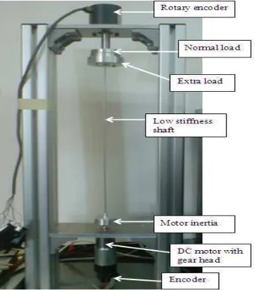
To evaluate the effectiveness and robustness of the improved NCTF controller with anti-windup PI compensator to inertia and friction variations, the controllers are applied to an experiment two-mass rotary positioning system shown in Figure 7. The positioning system consists of a direct current motor, a driver, motor and load mass and low stiffness shaft. The controller is implemented digitally with a 1 ms sampling period. An optical encoder with a 10000 pulse per revolution is used for measuring displacement. The angular load velocity used in the experiment is obtained by applying a backward difference algorithm to the measured angular load displacement. The control signal is sent to the driver through a digital to analog converter.
The positioning performance is examined under two conditions namely Normal Object and Increased Inertia Object. Increased Inertia Object has about ten times load inertia than Normal Object.
Figure 7. The experimental two-mass rotary positioning system
(a) (b)
Figure 8. Nominal and increased object inertia: (a) Normal object, (b) Increased inertia object
Table 1. Object parameter comparison.
Object Inertia Friction
Normal load Jl=14.17x10⁻⁶ kgm2 τ fmax = 0.0027
Increased inertia load 2 x Jl τfmax
5 x Jl
10 x Jl
Increased friction object Jl 2 x τfmax
10 x τfmax
5.2. Equivalent PID Controller Design
According to Figure 4, the inclination, m and maximum error rate, h of the NCT are 81.169 and 61.6, respectively. When designing the PI compensator, design parameters for ζ
and ωn are chosen as 9.5 and 10.5 in order to evaluate the performance of NCTF controller
[15].
The performance of the positioning system controlled by NCTF controller is compared with the PID controller. The PID controller is designed based on relation with NCTF at small object motion. The conventional PID controllers have the following transfer function:
∫
++
= K e K edt K e
u P I D& (8)
By considering Fig. 5, the output of the PI compensator, u of the NCTF controller is:
∫
+
=K u K u dt
u P P I P (9)
Moreover based on Eq. (4) and (8), the equation can be rewritten as follows:
∫
++ +
= K K e K edt K e
u ( Pα2 I) Iα2 P& (10)
Hence, by comparing Eq. (8) and (10), its shown at small error the NCTF controller is equivalent to the conventional PID controller has the following parameters:
P paper, the PID controller tuned with Ziegler-Nichols and Tyres Luyben method is not discussed again since it gives bad performances in term of robustness to parameter variation [9, 15].
Table 2. Controller parameters.
5.3. Effect of The Tracking Gain, KT on Positioning Performance
The crucial problem for anti-windup PI compensator is the value of the tracking gain KT.
Although it is stated that a rule of thumb for the setting of KT is often KT = KIwhich corresponds
to b=1, but a higher values may give a further improvement in performances [17]. Therefore, in order to find the appropriate value of KT, an experimental has been done for different values of b
which represent the ratio between tracking gain KT and integral gain KI.
Figure 9 shows the effect of the tracking gain KT on the positioning performances. It
5.4. Comparison with Equivalent PID Controller.
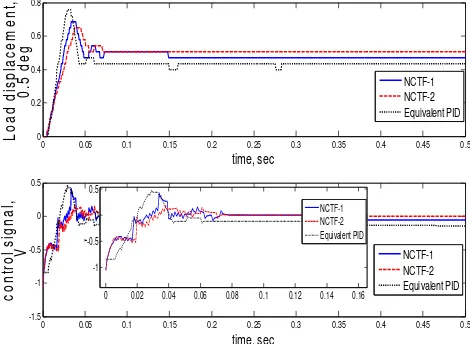
In this section, the performance of the positioning system controlled by the improved NCTF (NCTF-2) controller with anti-windup PI compensator is compared with that of the improved NCTF (NCTF-1) (i.e. without anti-windup compensator), and equivalent PID (E-PID) controllers. The positioning performance is evaluated based on percentage of overshoot, settling time, and steady-state error of the two-mass rotary positioning system. Figure 10 shows the step responses to a 0.5 deg step inputs when the controllers are used to control normal object. Their positioning performances are also summarized in Table 3. Moreover, for the experimental results, all controllers give positioning accuracy near the sensor resolution, which is 0.036 deg.
Figure 10. Comparison of response 0.5 deg step input, Normal object
Here, it is clear that all of the controllers produce similar response. Hence, in terms of overshoot and settling time, all of the controllers give similar performance.
In order to evaluate the robustness of the control systems to inertia variation, all of the controllers are implemented on object with inertia is ten time (10 x Jl) of the nominal one. Figure
11 shows the step responses to 0.5 step inputs when all of the controllers are implemented for controlling increased object inertia. Table 2 shows the positioning performance resulting from all of the controllers. Figure 11 and Table 3 show that both NCTF controllers give a better
Figure 11. Comparison of response 0.5 deg step input, Increase inertia object (10xJl)
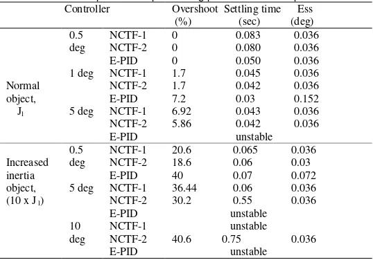
Next, experiment was done for a larger step input so that the actuator reached saturation. Figure 12 shows the step responses to a 10 deg step input when all of the controllers are implemented for controlling increased object inertia. Table 2 shows the positioning performance resulting from all of the controllers. The saturation of the actuator occurs as shown in Figure 12. The saturation of the actuator causes an integrator windup when the positioning system is controlled by both NCTF-1 and E-PID controller. The positioning performance of the positioning system with NCTF-1 is unstable because of the integrator windup. Hence the NCTF-1 becomes less robust to inertia variation when the saturation occurs in comparison with that with NCTF-2 controller. On the other hand, NCTF-2 which uses anti-windup PI compensator can successfully compensate the effect of integrator anti-windup due to actuator saturation. As the results show, the improved NCTF controller (NCTF-2) gives a smaller overshoot and a shorter settling time than the other controllers.
0 0.05 0.1 0.15 0.2 0.25 0.3 0.35 0.4 0.45 0.5
Figure 12. Comparison of 10 deg step response for increased inertia object, (10 x Jl)
Table 3. Experimental positioning performance comparison Controller Overshoot Settling time Ess used instead of a conventional PI compensator. Through an experimental using two-mass rotary positioning system, the effectiveness of the NCTF controller with anti-windup PI compensator is
evaluated. It proved that the used of anti-windup PI compensator is effective to overcome the problem due to integrator windup. Moreover, the results also show that improved NCTF controller with anti-windup PI compensator is more robust to inertia variation than conventional PI compensator and Equivalent PID controller. Lastly, the application of the NCTF control concept for multi-mass positioning systems may be an interesting topic for further investigation.
References
[1] Amstrong-Helouvry B, Dupont P, De Witt C. A Survey of Models, Analysis Tools and Compensation Method for the Control of Machines with Friction. Automatica. 1994; 30: 1083-1138.
[2] Kempf C, Kobayashi S. Disturbance Observer and Feedforward Design for a High speed direct-drive Positioning Table. IEEE Trans. On Control systems Technology. 1999; 7(5): 513-526.
[3] Park MH, Won CY. Time Optimal Control for Induction Motor servo System. IEEE Trans. On Power
Electronics. 1991; 6(3): 514-524.
[4] Li YF, Erikson B, Wilkander J. Sliding Mode Control of Two-mass Positioning systems. 14th Triennaial
World Congress IFAC. Beijing, China. 1999: 151-156.
[5] Shieh MY, Li TH. Design and Implementation of Integrated Fuzzy Logic Controller for a servo motor system. Mechatronic. 1998; 8: 217-240.
[6] Horgh JH. Neural Adaptive tracking control of a DC motor. Information sciences. 1999; 118: 1-13. [7] How to work with mechanical resonance in motion control systems. Control Engineering. 2000; 47(4):
5.
[8] Sato K, Wahyudi, Shimokohbe A. Design and Characteristics of Practical Control system for PTP Positioning. Trans of the Japan Society of Mechanical Engineers. 2001; 67(664): 222-228.
[9] Fitri MY, Wahyudi, R Akmeliawati. Improved NCTF Control Method for a Two Mass Point to Point
Positioning System. IEEE 3rd International Conference on Intelligent and Advanced systems (ICIAS
2010). Kuala Lumpur. Jun 2010.
[10] Wahyudi, Albagul A. Performance improvement of practical control method for positioning system in
the presence of actuator saturation. IEEE International Conference on Control Applications. Taipei.
2004; 296-302.
[11] K Astrom, T Hagglund. PID Controllers: Theory, Design, and Tuning. Handbook. Instrument Society of
America. 1995; 82-90.
[12] W Gharier. Fuzzy intervention in PID Controller design. ISIE. Pusan, Korea. 2001; 1639-1643.
[13] Wahyudi, Sato K, Shimokohbe A. Robustness Evaluation of New Practical Control Method for PTP
Postioning Systems. IEEE/ASME International Conference on Advanced Intelligent Mechatronics.
2001; 843-848.
[14] Oppenheim A.V. & Schafer R.W, Discrete Time Signal Processing. Englewood Cliffs, Prentice Hall. 1999.
[15] Fitri MY, Wahyudi, R Akmeliawati. Performance Evaluation of Improved Practical Control Method of
Two-Mass PTP Positioning System. IEEE Symposium on Industrial Electronics & Applications (ISIEA
2010). Penang. 2010; 550-555.
[16] William East & Brian Lantz, Notch Filter Design. August 29, 2005.
[17] S Crawshaw, G Vinnicombe. Anti-windup synthesis for guaranteed L2 performance.Proc. IEEE Conference on Decision and Control. 2000.