UNIVERSITI TEKNIKAL MALAYSIA MELAKA
DESIGN A DUSTPAN AND ANALYZE THE OPTIMUM
INJECTION MOLDING PARAMETERS FOR A GATE
LOCATION
This report submitted in accordance with requirement of the Universiti Teknikal Malaysia Melaka (UTeM) for the Bachelor Degree of Manufacturing Engineering
(Manufacturing Design) (Hons.)
by
NADIAH BINTI AHMAD TERMIZI
B051210224
910811085304
UNIVERSITI TEKNIKAL MALAYSIA MELAKA
BORANG PENGESAHAN STATUS LAPORAN PROJEK SARJANA MUDA
TAJUK: Design a Dustpan and Analyze the Optimum Injection Molding Parameters for a Gate Location
SESI PENGAJIAN: 2014/15 Semester 2
Saya NADIAH BINTI AHMAD TERMIZI
mengaku membenarkan Laporan PSM ini disimpan di Perpustakaan Universiti Teknikal Malaysia Melaka (UTeM) dengan syarat-syarat kegunaan seperti berikut: 1. Laporan PSM adalah hak milik Universiti Teknikal Malaysia Melaka dan penulis. 2. Perpustakaan Universiti Teknikal Malaysia Melaka dibenarkan membuat salinan
untuk tujuan pengajian sahaja dengan izin penulis.
3. Perpustakaan dibenarkan membuat salinan laporan PSM ini sebagai bahan pertukaran antara institusi pengajian tinggi.
DECLARATION
I hereby, declared this report entitled “Design a Dustpan and Analyze The Optimum Injection Molding Parameters for A Gate Location” is the result of
my own research except as cited in references.
Signature : ………
Author’s Name : NADIAH BINTI AHMAD TERMIZI
APPROVAL
This report is submitted to the Faculty of Manufacturing Engineering of UTeM as a partial fulfillment of the requirement for the degree of Bachelor of Manufacturing Engineering (Manufacturing Design) (Hons.). The member of the supervisory committee is as follow:
………. (Project Supervisor)
ABSTRAK
ABSTRACT
DEDICATION
My special dedication to my beloved mother, Jamiah binti Ramli, and my beloved father, Ahmad Termizi bin Bidin for their loves and supports which never end and with the loves and supports given to me, I managed to go through 4 years of my study which full with challenges and hunches. To beloved friends of 4BMFR who have been with me
ACKNOWLEDGEMENT
TABLE OF CONTENT
2.1.3 Common Defect in Injection Molding 8
2.1.4 Injection Molding Parameter 12
2.2 Material 13
2.2.1 Properties of Plastics 13
2.2.2 Classification of Plastic 14
2.2.3 Polypropylene 14
2.3 Molds 16
2.3.1 Type of Mold 17
2.3.3 Feeding System Design 20 2.4 Part Design Guideline for Injection Molding Molded Plastic Part 21
2.4.1 Primary Wall 21
2.4.2 Ribs, Gussets and Bosses 23
2.4.3 Corners, Fillet and Radii 26
2.4.4 Taper and Draft Angles 26
2.5 Analysis of Plastic Flow 27
2.5.1 Application of simulation software 27 2.5.2 Analysis the optimum feeding system 28 2.5.3 Analysis the parameter optimization 29
CHAPTER 3: METHODOLOGY 30
3.1 Project Flow Chart 30
3.2 Problem statement 32
3.2.1 Gather raw data from observation 32
3.3 Identify the objective and scope 32
3.4 Literature Review on previous research 33
3.5 Product Design 33
3.5.1 Solidworks 2013 33
3.6 Concept Development and Selection Process 34 3.6.1 Concept Selection Using Pugh Matrix Method 34
3.7 Material Selection of Resin 37
3.7.1 CES EduPack Software 37
3.9 Solidworks Plastics 2013 38
3.9.1 Feeding System Design 38
3.9.2 Mold Flow Simulation 40
CHAPTER 4: RESULT AND DISCUSSION 41
4.1 Concept Design 41
4.1.1 Design 1 41
4.1.3 Design 3 42
CHAPTER 5: CONCLUSION AND RECOMMENDATION 69
REFERENCES 70
LIST OF TABLES
2.1 Injection molding parameter 12
2.3 General properties of plastics 13
2.4 Shrinkage percentage of common thermoplastic material 16
2.5 Recommended wall thickness 23
3.1 Typical runner diameters depends on material 39
4.1 Concept Screening 45
4.2 Concept Scoring 47
4.3 Feeding design 50
4.4 Clamping unit the machine 51
4.5 Injection unit the machine 52
4.6 Drive and connection unit the machine 52
4.7 Gate location 60
4.8 Material Flow for Gate Location 1 61
4.9 Material Flow for Gate Location 2 64
4.10 Material Flow for Gate Location 3 67
LIST OF FIGURES
2.1 Typical injection molding machine 6
2.2 Injection unit 6
2.3 Clamping unit 7
2.4 Injection molding cycle 8
2.5 Sink Mark 9
2.13 Schematic diagram of core and cavity 19 2.14 Example of cavity and core for plastic spoon 20.
2.15 Sprue, Runner and Gate position. 21
2.16 Non-uniform wall thickness can lead to air traps 22
2.17 Thickness transitions 22
2.18(a) Sink wall opposite ribs 24
2.18(b) Design guidelines 24
2.19 Gussets design 24
2.20(a) Typical bosses design 25
2.20(b) Connecting bosses to walls 25
2.21 Corners, Fillet and Radii design 26
2.22 Draft on inside and outside surfaces of side wall 26
2.23 Common draft guideline. 27
2.24 Simulation of material flow 28
3.1 Project Flowchart 31
3.7 Example of plastic flow simulation using Solidworks Plastics 2013 40
LIST OF ABBREVIATIONS, SYMBOLS AND
NOMENCLATURE
PIM Plastic Injection Molding PP Polypropylene
PC Polycarbonate
ABS Acrylonitrile Butadiene Styrene ANOVA Analysis of Variance
CHAPTER 1
INTRODUCTION
This chapter will explained about the project background all about the design and analysis of the plastic flow in injection molding. This also includes the problem statement and objective of the research. The scope on what being study is also important point need to elaborate.
1.1 Project Background
This project is about designing and analysis the mold flow in plastic injection molding. Plastic is a material that can be produced by injection molding machine to form any shape for consumer product. Plastic for injection molding may be classified into two types: thermoplastics and thermoset. Many different commercial methods are accustomed to produce thermoplastic products. Each of the method used to produce thermoplastics products has its specific design requirements, along with limitations.
This project will explain about the most frequent processing method for thermoplastics, injection molding which can be forcing a molten plastic into molds at high pressure. The plastic then forms to the structure of the mold as it cools and solidifies. Usually a quick-cycle process, injection molding can produce large quantities of parts, accommodate a wide selection of part sizes, offer excellent part-to-part repeatability, and make parts with relatively tight tolerances (Yeager, 2000).
Design phase is the most crucial in product development to achieve high quality of product produce by injection molding. The designing process plays important role in injection molding parts, there is several limitation need to be consider when producing with injection molding such as the design must have uniform wall thickness, ribs thickness should be low that wall thickness, rounded corner design, draft angle, bosses thickness and undercuts.
This study also is to analyze the plastic flow in injection molding mold as already known, mold simulation is a method to observe the material flow in mold during injection process. The purpose of this method is to analyze the optimum parameter need to be confirmed to produce high quality of plastic injection part without any defect. Material flow simulation may determine optimal gate location and optimized runner system, forecast weld line, determine the location of air trap, shear stress, filling time, filling possibility, melt temperature, gate freezing time, pressure holding time and pressure. By applying this mold flow simulation before manufacture in real injection molding, manufactures can predict and avoid manufacturing defect on part in earlier stages of part and mold design.
1.2 Problem Statement
and injection velocity is trial-and-error method, where this process depends on engineers experienced and intuition in determining the initial process parameter setting. It can be prove that this method is not the best and can be practice for future product productivity because it leads to costly process and time consuming (Lahoti, et al., 2013).
There are several common defects occurred at plastic part such as sink marks, flashing, flow marks, short shot, warping, weld line, burn marks, color streaking, spotted whitening, and jetting. Continuously producing a part with low quality (defect) will cause a waste in term of cost and material. By using simulation, it can reduce the occurrence of defect on plastic part due to the analysis of mold flow in injection molding. From the mold flow analysis, it can determine the optimum parameter need to be apply at the plastic part for injection molding and indirectly defined if the injection molding for the part might cause defect or not.
Improve the plastic flow in injection mold. By applying simulation and analysis on mold flow in injection molding before the real production, we can improve the plastic part quality in terms of its design, strength and defect. Plastic is a material that will not degrade for a quite long terms, thus it is important to design and produce a plastic part with high quality for long terms useable. It will reduce consume of material and time producing the parts.
1.3 Objective
The main objectives of this research are: a) To design a new dustpan.
b) To design feeding system for plastic flow analysis. c) To perform plastics flow analysis of a dustpan.
d) To obtain the optimum the injection molding parameters for a gate location.
1.4 Scope
CHAPTER 2
LITERATURE REVIEW
This chapter explains about the previous research of injection molding related topics. The main topics discussed in this chapter are injection molding process, common defect in injection molding, injection molding parameter, material in injection molding, type of mold, feeding system design, part design guidelines, and analysis of plastic flow in injection molding process.
2.1 Injection Molding
Injection molding is a process of manufacture plastics part according to required specifications by melting the plastic material and forcing it under certain pressure into sprue, runner, gate and reach to mold cavity. Injection molding technologies reach up 32% to be used in plastic part production due to its ability to produce complex geometry shape with accurate dimension (Shakkarwal & Yadav, 2013).
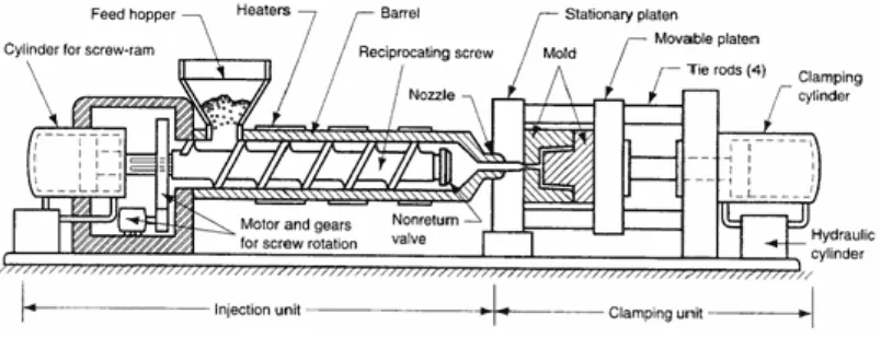
2.1.1 Injection Molding Machine
Figure 2.1: Typical injection molding machine (Narote, et al., 2014).
Typical injection machine shows in Figure 2.1 have injection unit and clamping unit where it is differs in injection molding machine. It is depends on the type of injection molding used. Common injection molding machine consist of two units:
a) Injection unit
The task of injection unit shows in Figure 2.2 is to melt the pallet material into liquid form or resin by accumulate the material in the screw chamber. The rotating screw breaks the solid material into small pieces and leads to liquid form to be injected into the cavity.
b) Clamping unit
The primary tasks of the clamping unit as illustrated in Figure 2.3 are expand and retract the cylinder whereby will open and close the core and cavity of the mold tightly during injection. There are three clamping types: mechanical, hydraulic and their combination.
Figure2.3: Clamping unit (Narote, et al., 2014)
2.1.2 Process and Cycle
A typical sequence of injection molding cycle as shown in Figure 2.4 is as follows:
a) Granules of plastics powder from feed hopper fed into an empty cylinder and
falls into the rotating of screw which conveys the material to the front of the cylinder. The material plasticized to a fluid state during its passage along the cylinder with the help of external heaters on the barrel. The back pressure
which have sufficient to push the screw back in the cylinder is to prevent some material may be escape through the nozzle. It can be used to equip a reservoir of fluid plastic in the leading of cylinder for injection.
c) Next, the injection of material into mold takes places due to the screw moved forward by the hydraulic cylinder. The material flow through the sprue, runner and gate to the cavity.
d) After a short intervalrance of the mold which called holding time, the screw
rotates backward and generate pressure in the cylinder, thus the screw force backward against low pressure in the barrel until energize the limit switch to stops the rotation of screw. The plasticized molten material is ready for the next cycle. The mold open and the article is ejected, a mold close again for next cycle (Narote, et al., 2014)
Figure 2.4: Injection Molding Cycle (Narote, et al., 2014)
2.1.3 Common Defect in Injection Molding
produce plastic part. There are several common defects occurred on plastic part for instance sink marks, flash, short shot, warping, weld line and flow marks.
2.1.3.1 Sink Marks
Refer to Figure 2.5, sink is the depression or a deep recess or notch on the edge or surface of a part that do not mimic the mold steel surface. Sink and cavity are the signal of the distribution of stress on uniform across the part and are alert signs that the part may not perform as required. The possible cause of sink mark is thick ribs walls of part itself and should be reduced by design the thickness of the ribs lower than thickness of the part. (Bozelli, 2007)
Figure 2.5: Sink Mark (Beaumont, 2008)
2.1.3.2 Short Shot