UNIVERSITI TEKNIKAL MALAYSIA MELAKA
DESIGN AND DEVELOP AN OUTDOOR THERMOELECTRIC
ENERGY GENERATOR
This report is submitted in accordance withthe requirement of the
UniversitiTeknikal Malaysia Melaka (UTeM) for the Bachelor in Manufacturing Engineering Technology (Process and Technology) with Honours.
by
MOHD NAZRIN BIN MOHD ZAINI B071210390
900818-06-5665
UNIVERSITI TEKNIKAL MALAYSIA MELAKA
BORANG PENGESAHAN STATUS LAPORAN PROJEK SARJANA MUDA
TAJUK: DESIGN AND DEVELOP AN OUTDOOR THERMOELECTRIC ENERGY
GENERATOR
SESI PENGAJIAN: 2015/16 Semester 1
Saya MOHD NAZRIN BIN MOHD ZAINI
mengaku membenarkan Laporan PSM ini disimpan di Perpustakaan Universiti Teknikal Malaysia Melaka (UTeM) dengan syarat-syarat kegunaan seperti berikut:
1. Laporan PSM adalah hak milik Universiti Teknikal Malaysia Melaka dan penulis. 2. Perpustakaan Universiti Teknikal Malaysia Melaka dibenarkan membuat salinan
untuk tujuan pengajian sahaja dengan izin penulis.
3. Perpustakaan dibenarkan membuat salinan laporan PSM ini sebagai bahan pertukaran antara institusi pengajian tinggi.
4. **Sila tandakan ( ) sebagaimana yang termaktubdalam AKTA RAHSIA RASMI 1972)
** JikaLaporan PSM ini SULIT at au TERHAD, silalampirkansurat daripadapihakberkuasa/ organisasiberkenaandenganmenyat akansekalisebabdant em
iii
DECLARATION
I hereby, declared this report entitled “Design and Develop An Outdoor Thermoelectric Energy Generator” is the results of my own research except as cited in references.
Signature :………
Name : MohdNazrin Bin MohdZaini
iv
APPROVAL
This report is submitted to the Faculty of Engineering Technology of UTeM as a partial fulfillment of the requirements for the Bachelor of Manufacturing Engineering Technology (Process and Technology) with Honours. The member of the supervisory is as follow:
v
ABSTRACT
vi
ABSTRAK
Kebanyakansumbertenagapadapadamasakiniyang
digunakandarisumbertenagaaslitidakbolehdiperbaharui,iajugamengancamsumbersem ulajadikita. Selainitu, sumbertenagadigunakanpadakadar yang berbahayajugapastibolehmemberikesanterhadapalamsekitardanjugabolehmeningkatk anpemanasan global. Projekinibertujuanuntukmencarisumbertenagabaru yang
memberifokusterhadapaktivitiperkhemahan yang
manabertujuanuntukmengecasalatkomunikasidanuntuklampu mini denganmenggunakansumbertenagaterpakai.Objektifprojekinijugaadalahmerekabentu kdanmembangunkanpenjanatenagatermoelektrikdi
kawasanluaruntukkegunaanperkhemahandisampingmenganalisiskecekapanvoltanyan g terhasildenganmenggunakanalatpenjana TEG (modulpenjanatermoelektrik) .Terdapattigakomponenutamapenjanaanelektrikiaitupengumpulhaba, sink habadan
TEG (modulpenjanatermoelektrik) .Kaedah
vii
This report is dedicated to my family. Thank you for your continuous support during my vital educational years. Without their patience, understanding and most of all
love, the completion of this work would not have been possible.
To my beloved parents,
RasidahBintiLuddin &
MohdZaini Bin Maarof
My siblings,
viii
NurAleaBintiMohdZaini
ACKNOWLEDGMENTS
“In The Name Of Allah, The Merciful, The Beneficent”
First of all, I would like to thanks Allah S.W.T, that have given me the opportunity to complete my Project SarjanaMuda (PSM) .Alhamdulillah, the report can be submitted on the due date. The successful of this project is because of the encouragement and support of many people. I also offer my sincere gratitude to my adviser EncikNazri bin Ahmad for his knowledge, understanding and most importantly patience while guiding me. I would like to say thank you to my parents and friend. With your support in times of difficulties and your understanding during my study, I feel like I could conquer every hardship and reach even higher.
ix
xi
LIST OF FIGURES
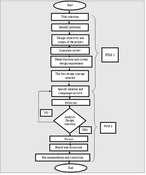
Figure 1.1 Flow Chart ... 6
Figure 2.1 Thermoelectric Power Generation ... 8
Figure 2.2Developed Between the Junctions ... 10
Figure 2.3Peltier Effect ... 11
Figure 2.4Typical Thermoelectric Module in Heat Pumping Configuration ... 12
Figure 2.5The Basic Structure of a TEG ... 14
Figure 2.6Basic Thermoelectric Circuit ... 18
Figure 2.7Schematic of Thermo-element ... 19
Figure 2.8Thermo-Element in Series ... 19
Figure 2.9Thermo-Element Module Construction ... 20
Figure 2.10a) Extruded Heat Sink, b) Bonded Fin Heat Sink c) High Density Extrusion, d) Forged Pin Fin Heat Sink. ... 22
Figure 2.11Primary Battery Charging Circuit ... 23
Figure 2.12 Schematic Diagram of Prototype Design ... 26
Figure 2.13Relation of Temperature Difference (∆T) with Respect to Power Output (W) with Load of 1Ω Resistance ... 26
Figure 3.1 Work Flow Chart ... 29
Figure 3.2Block Diagram for Thermoelectric Energy Generator ... 30
Figure 3.3 Finalized for Real Product Design ... 31
Figure 3.4Final Design Select ... 36
Figure 3.5Product Selection ... 38
Figure 3.6Ranking Mass or Cost Per Unit of Function ... 41
Figure 3.7Constraint Temperature Greater than 150̊C and Less than 400̊C ... 42
Figure 3.8Assembly Drawing ... 43
Figure 3.9 TEG Module Part ... 44
Figure 3.10Heat Sink Part ... 44
Figure 3.11 Heat Collector Part ... 45
Figure 3.12Wall Collector ... 45
Figure 3.13:Process Involve in Prototype Fabrication Project... 50
Figure 3.14:Dimension of Heat Collector ... 51
Figure 3.15:Dimension of Wall collector... 52
xii
Figure 3.17Cutting Process ... 53
Figure 3.18Bending process ... 53
Figure 3.19Drilling Process and Cutting process ... 54
Figure 3.20Assembly Process ... 55
Figure 3.21Experiment Setup... 56
Figure 3.22 Process Measure Temperature a) Cold Side b) Hot Side ... 57
Figure 3.23Electric Circuit ... 58
Figure 4.1 Graph of Limitation Hot Sidefor Three Different Materials ... 63
Figure 4.2 Graph of Limitation Cold Side for Three Different Materials ... 64
Figure 4.3Graph of Temperature Difference( Th-Tc) for Three Material ... 64
Figure 4.4 The Voltage For The Thermoelectric Module TEP-142T300plotted as a function ofTemperature difference across the device , ∆T ... 65
Figure 4.5The regression result for stainless steel by Using Mini Tab ... 66
Figure 4.6The Voltage for The Thermoelectric Module TEP-142T300plotted as a function ofTemperature difference across the device, ∆T ... 67
Figure 4.7The regression result for Cooper by Using Mini Tab ... 67
Figure 4.8 The Voltage for The Thermoelectric Module TEP-142T300plotted as a function ofTemperature difference across the device ... 68
Figure 4.9The Regression Result for Aluminium by Using Mini Tab ... 69
Figure5.1:Maximum service Temperature ... 71
Figure5.2:Voltage Versus Temperature Difference of Aluminium ... 73
Figure5.3:Voltage Versus Temperature Difference of Copper ... 73
xiii
LIST OF TABLE
Table 1.0: Chart Project Planning ... 4
Table 2.1: Specification and Properties of HZ-20 ... 17
Table 2.2: Prior Stove Researches ... 25
Table 3.1:Pugh Evaluation Method... 33
Table 3.2: House of Quality ... 35
Table 3.3:Weighted Rating Method ... 37
Table 3.4:Function, Constraints, Objectives and Free Variables ... 39
Table 3.5:List of Material ... 46
Table 3.6:List of Equipment ... 47
Table 3.7:Summarized Result of Three Test for Aluminium Collector... 57
Table 4.0: Result of Temperature for Stainless Steel Material ... 60
Table 4.1:Result of Temperature for Cooper material ... 61
xiv
LIST OF SYMBOLS AND ABBREVIATIONS
Symbols Parameter
A Surface Area,m²
I Current flowing Through the leg pair or module, A
K Thermal conductance
K* *Coverage Factor
P Power Generated by leg pair or module
Q Heat rate , W
R Electrical resistance of a module , Ω RTH Thermal resistance, K/W
T Temperature K or ºC
U Uncertainty in a measured quantity, % V Voltage across a leg pair or module , V/K ZT Figure of merit, dimensionless
α Seebeck coefficient, V
β Temperature difference across the module
∆T Module efficiency , %
λ Thermal conductivity, W/mk
π Peltier coefficient, W/A
ρ Electrical resistivily,Ωm
1
CHAPTER 1
INTRODUCTION
1.0 Introduction
With world that rapidly developing nowadays, a large number of energy sources charged at a dangerous rate and it's certainly can cause the elimination of our precious natural resources. Moreover, there are a lot of the energy resources that applied today are non-renewable natural resources like petroleum. Because of that, a lot of focus has been applied to overcome the adverse impact on this environment. To overcome this problem, research on forming the new alternative energy can reduced our reliance on non-renewable forms of energy and therefore save the environment, has become more important than ever before.The demand for renewable sources of energy is increasing due to an elevated concern about the global warming, climate change and the decline of fossil fuel reserves. Thermoelectric developer is one of the alternate sources for the growth of power.
2
As a measure against global warming, recovering waste heat and converting it into electrical energy is very effective. While there are various methods of recovering waste heat, much expectation is being entertained of the thermoelectric module that has no moving parts and that is capable of converting waste heat directly into electrical energy. Since discovery of the See beck effect, thermoelectric modules have been studied for more than 180 years. Nevertheless, the thermoelectric module has not become widespread yet. The major reasonfor this is the low efficiencies of conventional thermoelectric modules. In recent years, however, the characteristics of thermoelectric modules have improved so much that the prospect of thermoelectric power generation has rapidly become very bright. This paper describes the current status of development and the economics of thermoelectric modules for power generation.
The Advantages of Thermoelectric Generator:
a) Offer a potential in the direct conversation of waste energy to electric power irrespective of the cost of the thermal energy output.
b) Lower production cost
3 1.1 Problem Statement
The outdoor activity like camping is one of the best methods for people to release tension and spend time with their beloved family and friends. The usual problem when people joined a camping activity is the difficulty to get electric source to charge their devices like phone or mini lamp. The electrical generating appliances used nowadays are practical but not nature-friendly as it causes air pollution from the combustion of fuel. To overcome the problem, there is an alternative to generate electricity from the wasted heat of cooking stove by using concept thermoelectricity.
1.2 Objective of Project
The objectives of this project are:
i. To design and develop an outdoor thermoelectric energy generator for camping purpose.
ii. To analyse the efficiency of voltage generate by TEG module (thermoelectric generator)
1.3 Scope of Study
The scopes of this project are:
i. Designing and fabricate an outdoor thermoelectric energy generator attached on cooking stove for camping purpose.
ii. Use for rechargeable appliances like hand phone or mini lamp (5V DC conversation).
4
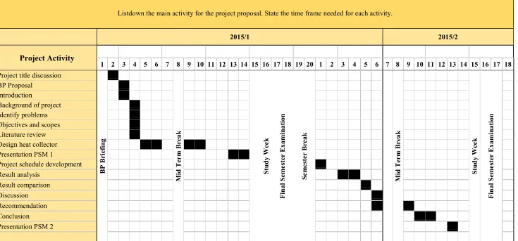
Table 1.0:Gant Project Planning
Listdown the main activity for the project proposal. State the time frame needed for each activity.
5 1.4 Project Planning
Table 1.0shows the progress for the whole semester 1 of the Final Year Project (FYP). Weekly meetings with supervisors have been done on Wednesdays to understand the project as well as to manage the weekly schedule.
For the first week of semester 1, a discussion with supervisor is done to discuss about the project as shown in Figure 1.1. Then, it's continued with searching the related journal to get more understanding about project and also started to write the literature review. The purpose of the literature review to establish a theoretical framework for research project and it is reported in chapter 2 of this research. Identify the problem of project is important to ensure that objectives of the project are achieved at the end of the FYP.
Chapter 3 or project methodology describes the particulars of the materials and component used in the present work and the procedure for fabricate with the best concept and design selected. Process screening is been done in this chapter to select the best concept.
7
CHAPTER 2
LITERATURE REVIEW
2.0 Introduction
This chapter would generally discuss aboutheat transfer mechanisms and performance optimization of thermoelectric generators (TEG). Related themain objective of this project. This project recommended the further studies to measure the efficiency thermoelectric system idea to camping stove cooking.
2.1 Thermoelectric
8
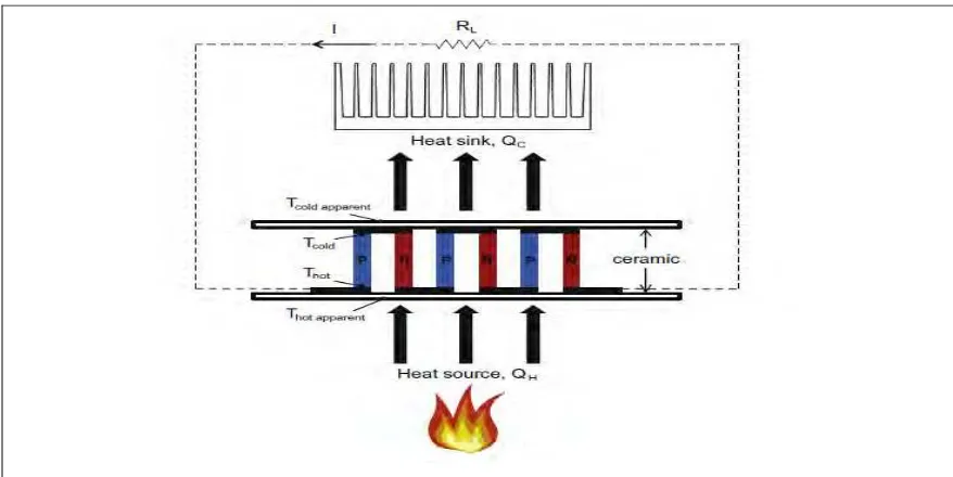
Figure 2.1: Thermoelectric Power Generation (S.M O Shaughnessy, 2012)
A thermoelectric module is clamped between a heat source and a heat sink. Heat flows from the heat source through the module and is dissipated by the heat sink, and electricity is produced by the module. The thermoelectric module consists of pairs of p– n thermo-elements. The positive (p-type) and negative (n-type) doped semiconductor elements are connected electrically in series and thermally in parallel. Initially, the conductors in the module possess a uniform distribution of charge carriers. However, the heat input to the module, Heat source QH, creates a temperature differenceacross the p– n thermoelements. The Seebeck effect is described by Rowe. The free carriers at the hot end have greater kinetic energy and diffuse to the cold end. The accumulation of charge results in a back emf which resists further flow of charge. If the temperature difference across these junctions is maintained, an open circuit voltage V is generated according to:-
V = α (TH – TC) Equation 2.1
9
thermoelectric materials are available for use in generators. Rowe describes the ‘worth’ of thermoelectric materials, expressed by a quantity Z, known as the:
Where λ is the thermal conductivity, σ the electrical conductivity, and ρ is the electrical resistivity(Minnich A. J,2009).
2.2 Background and Theory
Thermoelectric device are essentially solid state device that can change energy from heat to electricity or the other way around. Devices are regularly made up of semiconductor materials, the most widely recognized being bismuth telluride. A regular arrangement of a thermoelectric module consist of numerous leg sets made of semiconductor pellets, joined together utilizing contact tabs made of high conductivity materials(Sachit,2013)
2.2.1 Seebeck Effect
10
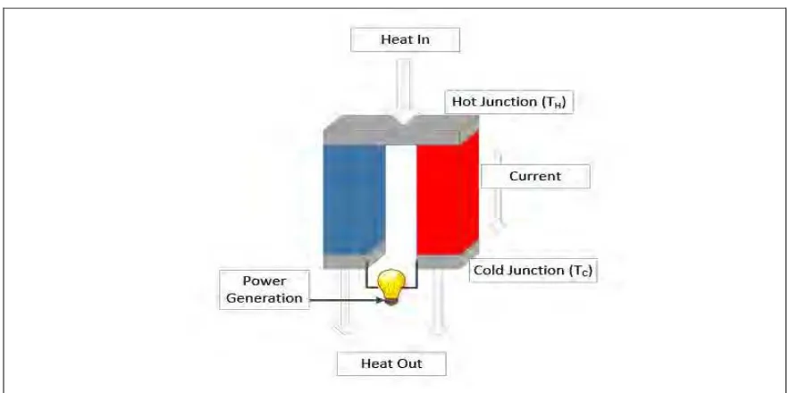
Figure 2.2:Developed Between The Junctions (Satchit, 2013)
The voltage produced is proportional to the temperature difference between the two junctions.
This is given by: