UNIVERSITI TEKNIKAL MALAYSIA MELAKA
INVESTIGATION OF DESIGN RULE FOR FDM SYSTEM IN
ADDITIVE MANUFACTURING: A CASE STUDY OF A
BLENDER JAR
This report submitted in accordance with requirement of the Universiti Teknikal Malaysia Melaka (UTeM) for the Bachelor Degree of Manufacturing Engineering
(Manufacturing Design) with Honours.
by
ANIZ FARZNOR BT SARIFFUDDIN HUSSANI
B051110212
UNIVERSITI TEKNIKAL MALAYSIA MELAKA
BORANG PENGESAHAN STATUS LAPORAN PROJEK SARJANA MUDA
TAJUK: Invest igat ion Of Design Rules For FDM Syst em: A Case St udy Of A Blender
Jar.
SESI PENGAJIAN: 2014/ 15 Semest er 2
Saya ANIZ FARZNOR BT SARIFFUDDIN HUSSANI
mengaku membenarkan Laporan PSM ini disimpan di Perpust akaan Universit i Teknikal Malaysia Melaka (UTeM) dengan syarat -syarat kegunaan sepert i berikut :
1. Laporan PSM adalah hak milik Universit i Teknikal Malaysia Melaka dan penulis. 2. Perpust akaan Universit i Teknikal Malaysia Melaka dibenarkan membuat salinan
unt uk t uj uan pengaj ian sahaj a dengan izin penulis.
3. Perpust akaan dibenarkan membuat salinan laporan PSM ini sebagai bahan pert ukaran ant ara inst it usi pengaj ian t inggi.
4. **Sila t andakan (√)
SULIT
TERHAD
TIDAK TERHAD
(Mengandungi maklumat yang berdarj ah keselamat an at au kepent ingan Malaysiasebagaimana yang t ermakt ub dalam AKTA RAHSIA RASMI 1972)
(Mengandungi maklumat TERHAD yang t elah dit ent ukan oleh organisasi/ badan di mana penyelidikan dij alankan)
Alamat Tet ap:
ABSTRAK
Teknologi tambahan baru (AM) digunakan untuk membuat plastik dan bahagian logam lapisan demi lapisan. Walaupun AM menyediakan banyak potensi dan manfaat seperti membuat bahagian-bahagian yang sangat kompleks, teknologi ini masih jarang ditubuhkan untuk tujuan pengeluaran produk yang berfungsi. Salah satu faktor yang mempengaruhi had penubuhannya adalah kekurangan peraturan reka bentuk untuk AM. Malah sebilangan besar kajian kes dapat diketahui bahawa reka bentuk AM kekurangan. Dalam usaha untuk menyokong reka bentuk yang sesuai untuk AM, konkrit dan reka bentuk bebas diperlukan. Keberkesanan kaedah reka bentuk yang tidak terkenal. Projek ini akan mengkaji keberkesanan kaedah-kaedah reka bentuk untuk sistem FDM. Untuk mengkaji keberkesanan kaedah-kaedah reka bentuk, kaedah-kaedah reka bentuk akan digunakan pada balang pengisar yang sedia ada. Analisis unsur terhingga (FEA) akan dianalisis pada kedua-dua reka bentuk yang sedia ada dan reka bentuk baru untuk membuat perbandingan. Terdapat banyak kelebihan menggunakan kaedah-kaedah reka bentuk. Walau bagaimanapun, didapati bahawa terdapat juga keburukan dengan menggunakan kaedah-kaedah reka bentuk. Kelebihannya ialah ia memberi tekanan Von Mises yang tinggi dimana ia adalah baik kerana ia dapat mengatasi beban yang lebih banyak untuk bahan untuk mula bengkok. Selain itu perubahan dari bentuk asal adalah lebih kecil disebabkan oleh sesaran yang lebih kecil daripada reka bentuk lama. Kelemahannya adalah ia mempunyai faktor keselamatan yang lebih kecil daripada reka bentuk lama kerana tekanan Von Mises yang tinggi. Reka bentuk baru itu juga mengambil masa yang lebih pendek dan menggunakan bilangan bahan yang lebih kecil untuk membuat prototaip daripada reka bentuk lama. Dengan membandingkan reka bentuk yang sedia ada dan reka bentuk baru, kaedah reka bentuk yang sesuai untuk digunakan untuk membuat prototaip FDM akan diketahui. Walau bagaimanapun, disebabkan banyak halangan semasa melakukan projek, analisis yang sesuai telah dicadangkan untuk penambahbaikan kajian di masa depan.
ABSTRACT
ACKNOWLEDGEMENT
Alhamdullilah, for I am very grateful to ALLAH S.W.T for giving me enough strength and courage to finally finish up this final year project and its report. For without the help He has given along with His permission, all may not have been completed. This project was possible to thanks to my dear supervisor, Dr. Shajahan Bin Maidin with all his guidance and commitment in guiding and supporting me in completing this project. Dr. Shajahan has helped me a lot in solving all the problems that occur during completing this project. Once again I would like to thank him for all the comments, amendments and patience towards my deficiency.
I also would like to express my gratitude for my entire classmate especially Norfazleen Bt Zakaria for her enormous assistance, and to those who have been helping directly or indirectly in completing this final year project as well as its report. All of my hard work will meant nothing without the inspirational and motivational from all of them. And lastly, I would like to give my thanks to the patience and the support from my beloved mother, Siti Roslina Bt Shaikh Hashim as well as to my beloved family. For they, has given me the strength to complete this report entirely and I will always be grateful for having them as my family.
Thank You
TABLE OF CONTENT
Abstrak i
Abstract ii
Acknowledgement iii
Table of Content iv
List of Tables viii
List of Figures x
List of abbreviations, symbols and nomenclature xi
CHAPTER 1: INTRODUCTION 1
1.1 Introduction 1
1.2 Problem Statement 2
1.3 Aims 2
1.4 Objectives 2
1.5 Scope 3
1.6 Project Planning Gantt Chart 4
CHAPTER 2: LITERATURE REVIEW 6
2.1 Additive Manufacturing (AM) 6
2.1.1 Definition of AM 6
2.1.2 Basic Steps of AM 7
2.1.3 The Generic AM Process 7
2.1.4.1 Fused Deposition Modelling 10
2.1.4.2 Stereolithography (SLA) 11
2.1.4.3 Selective Laser Sintering 13
2.1.4.4 EBM 13
2.1.5 Advantages/Disadvantages of AM 14
2.1.6 Applications of AM 15
2.1.6.1 Lightweight Machines. 15
2.1.6.2 Architectural Modeling. 15
2.1.6.3 Medical Applications 16
2.1.6.4 Improving the Manufacturing of Fuel Cells 17 2.1.6.5 Additive Manufacturing in Art 18 2.1.6.6 Additive Manufacturing for Hobbyist 18
2.2 FDM System 18
2.2.1 FDM History 18
2.2.2 Build materials 19
2.2.3 FDM Working Principle 19
2.2.4 Advantages of FDM 20
2.3 Design Rules of FDM 20
2.3.1 Method for the development of design rules 20
2.3.2 Definition of standard elements 21
2.3.3 Basic Elements 21
2.3.4 Element Transitions 21
2.3.4.1 Design rules of element transition 22
2.3.5 Aggregated Structures 27
2.3.5.1 Design rules of aggregated structures 27
CHAPTER 3: METHODOLOGY 30
3.1 Introduction 30
3.2 Design rule used for FDM system 30
3.2.1 Thickness and Edge in Element Transition 30 3.2.2 Starting Position and Material Accumulation in Aggregated 31
Structures
3.3 Project Planning 34
3.3.1 Flowchart 35
3.3.2 Gantt Chart 36
3.3 Identify Existing Design 39
3.5 Remodelling of Existing Design 39
3.6 Modelling using SolidWork software 39
3.7 Finite Element Analysis (FEA) using SolidWork software. 40
3.8 Prototype 40
CHAPTER 4: RESULT AND DISCUSSION 41
4.1 3D CAD Modelling using SolidWork software. 41 4.2 Differences of 3D CAD Modelling of Each Design Rules. 43
4.2.1 Material Accumulation 43
4.2.2 Island’s starting position 43
4.2.3 Outer Edge Shape 44
4.2.4 Thickness 45
4.3 Controlled Variable 45
4.3.2 Material Used 46 4.4 Finite Element Analysis (FEA) for Edge and Thickness Design Rules 47
4.4.1 Direction Of Fixture And Force Applied 47
4.4.2 Von Mises stress 48
4.4.3 Displacement 48
4.4.4 Deformation Shape 49
4.4.5 Factor of Safety (FOS) 50
4.5 Finite Element Analysis (FEA) for island’s starting position 51 4.5.1 Direction Of Fixture And Force Applied 51
4.5.2 Von Mises Stress 52
4.5.3 Displacement 52
4.5.4 Deformation shape 53
4.5.5 Factor of safety (FOS) 54
4.6 Building Time And Material Length For Material Accumulation 55
CHAPTER 5: CONCLUSION 57
5.1 Conclusion 57
5.2 Recommendation 58
REFERENCES 59
List of Tables
Table 1.1 Gantt Chart PSM 1 4
Table 1.2 Gantt Chart PSM 2 5
Table 2.1 Historical development of RP and with any related technologies. 7
Table 2.2 Design Rules of Element Transition 23
Table 2.3 Design Rules of Aggregated Structures 28
Table 3.1 Design rules of element transition 32
Table 3.2 Design rules of aggregated structures. 33
Table 3.3 Gantt Chart of PSM I 37
Table 3.4 Gantt Chart of PSM II 38
Table 4.1 3D CAD Modelling of Old Design and New Design 42
Table 4.2 Force applied in FEA. 46
Table 4.3 Material used and its properties. 47
Table 4.4 Direction of fixture. 47
Table 4.5 Direction of force applied. 48
Table 4.6 FEA of Von Mises Stress 48
Table 4.7 FEA of displacement. 49
Table 4.8 FEA of deformation shape. 49
Table 4.9 FEA result of FOS. 50
Table 4.10 Direction of fixture. 51
Table 4.11 Direction Of Force Applied. 51
Table 4.13 FEA Result Of Displacement. 53
Table 4.14 FEA Result Of Deformation Shape. 53
Table 4.15 FEA result of FOS. 54
Table 4.16 Building time and material length. 55
List of Figures
Figure 2.1 Generic process of CAD to part 8
Figure 2.2 Fused Deposition Modelling. 11
Figure 2.3 Stereolithography. 12
Figure 2.4 FDM Technology 19
Figure 3.1 Overall Flowchart 35
Figure 3.2 Example of blender jar design. 39
Figure 4.1 The differences of height of the body of blender jar. 43
Figure 4.2 The differences in island’s position 43
Figure 4.3 Shape of edge of blender jar. 44
LIST OF ABBREVIATIONS, SYMBOLS AND
NOMENCLATURE
μm - micrometer
kV - kilovolt
3D - 3 Dimensional
ABS - Acrylonitrile Butadiene Styrene
AM - Additive Manufacturing
CAD - Computer Aided Design
DIY - Do it yourself
EBM - Electron Beam Melting
FEA - Finite Element Analysis
FDM - Fused Deposition Modelling
FOS - Factor of Safety
LOM - Laminated Object Manufacturing
MPa - Mega Pascal
PA - Polyamide
PC - Polycarbonate
PEMFCs - polymer electrolyte membrane fuel cells
PPSF - Polyphenylsulfone
RP - Rapid Prototyping
SLA - Stereolithography
SLS - Selective Laser Sintering
STL - Stereolitography file
CHAPTER 1
INTRODUCTION
This chapter introduces the project as well as briefly describe the aims, objectives and its scope. This chapter will also provide an overview of the project’s implementation.
1.1 Introduction
Additive manufacturing (AM) technologies refers to a process by which digital 3D design data is used to create plastic and metal parts layer by layer by depositing material (Kaifui and Aldo, 2012). The technology first developed with Stereolithography in the 1980s. Since then, AM was used for prototype production purposes only. Recently, with the increasing development of important technological and material enable AM applicability for the creation of end-used parts (Guido and Detmar, 2013). Thus, AM more and more turns to a production capable technology.
The strengths of AM lie in those areas where conventional machines reach its limitations. Using AM in terms of direct manufacturing to manufacture functional parts new advantages can be gained due to the layer by layer manufacturing. Thereby the extension of design freedoms is one of AM most remarkable potential. It describes a professional production technique permit the manufacturability of highly complex parts which cannot be produced with conventional technologies of material removal like milling or casting. Instead of milling a work piece from solid block, for example, AM builds components layer by layer using materials which are available
in fine powder form. A range of different metals, plastics and composite materials may be used. The technology is of interest where a new approach to design and manufacturing is required so as to come up with solutions. It allows a design driven manufacturing process where design determines production and not the other way around. What is more, AM enables for highly complex parts which can still be extremely light and stable (Kaifui and Aldo, 2012). It produce a high degree of design freedom, the optimisation and integration of functional features, the manufacture of small batch sizes at reasonable unit costs and a high degree of product customisation even in serial production.
1.2 Problem Statement
Although AM provides lots of potential and benefit such as manufacturability of highly complex parts, the technology is still rarely industrial established for end-used part production purposes. One limiting factor that affects its establishment is the insufficient availability of design rules for AM. Indeed, large numbers of case studies are known that exemplarily present AM design freedoms. In order to support a suitable design for AM, concrete and function independent design rules are required. The effectiveness of the design rules is not well known. This project will study the effectiveness of the design rules for FDM system.
1.3 Aims
The aim of this project is to investigate the design rule for FDM system.
1.4 Objectives
1. To produce CAD model of a blender jar.
2. To apply the design rule for FDM system to the CAD model of the blender jar.
1.5 Scope
Scope of this study apply the design rules for FDM system of AM process developed by Adam, G. a. O., & Zimmer, D. (2014). From the design rules of FDM system, the design rules that will be chosen to apply on the blender jar is the thickness, edge, material accumulation and island’s starting position because the design rules are suitable to be apply to the blender jar due to blender jar features. The design rules of FDM system will be applied to the blender jar because blender jar is a consumer product and suitable to be produce using FDM machine.
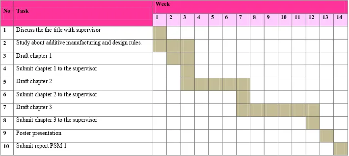
1.6 Project Planning Gantt Chart
Table 1.1: Gantt Chart of PSM I
No Task
Week
1 2 3 4 5 6 7 8 9 10 11 12 13 14
1 Discuss the the title with supervisor
2 Study about additive manufacturing and design rules.
3 Draft chapter 1
4 Submit chapter 1 to the supervisor
5 Draft chapter 2
6 Submit chapter 2 to the supervisor
7 Draft chapter 3
8 Submit chapter 3 to the supervisor
9 Poster presentation
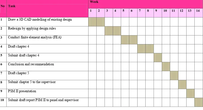
Table 1.2: Gantt Chart of PSM II
No Task
Week
1 2 3 4 5 6 7 8 9 10 11 12 13 14
1 Draw a 3D CAD modelling of existing design
2 Redesign by applying design rules
3 Conduct finite element analysis (FEA)
4 Draft chapter 4
5 Submit draft chapter 4
6 Conclusion and recommendation
7 Draft chapter 5
8 Submit chapter 5 to the supervisor
9 PSM II presentation
10 Submit draft report PSM II to panel and supervisor
CHAPTER 2
LITERATURE REVIEW
This chapter will provide an initial understanding regarding the definition of AM, basic steps in AM system, and the techniques known to the public. This chapter also will provide information on the benefits of AM along with the limitations of AM and also the design rules for AM.
2.1 Additive Manufacturing(AM)
2.1.1 Definition of AM
Table 2.1: Historical development of RP and with any related technologies(Chua and Leong, 2000)
2.1.2 Basic Steps in AM
In RP, according to Aarnio (2010) there basic step that needs in order to be used dependent on the criteria mentioned by Chua previously. Although there are several RP techniques was indeed mentioned, each employs the same basic technique .The steps are making 3D CAD model, convert to STL format, and slice each file into thin layers, constructing the model one layer a top another as well as cleaning and completing the model.
2.1.3 The Generic AM Process
According Gibson, Rosen and Stucker (2010), AM involves several of steps that move from virtual CAD description towards physical resultant part. Different products will involve AM in different ways and to different degrees. Small, relatively easy products may just create usage of AM for visualization models, while larger, more complex products with greater engineering information could involve AM during numerous phases and iterations throughout the development process. Furthermore, beginning stages of the product development process may just require rough parts, with AM being used because of the speed at which they can be created.
At later phases of the process, parts may need careful cleaning and postprocessing (including sanding, surface preparation and painting) before they are used, with AM being helpful here due to the complexity of form that can be produced without having to think about tooling. Later on, we will study thoroughly the different stages regarding the AM process, but to summarize, most AM processes involve, to some degree at least, the following eight steps as illustrated in Figure 2.1.
Figure 2.1: Generic process of CAD to part (Gibson, Rosen and Stucker, 2010)
Step 1: CAD
All AM parts must start from a software model that fully describes the external geometry. This can involve the use of almost any professional CAD solid modelling software, but the output must be a 3D solid or surface representation. Reverse engineering equipment (e.g., laser scanning) can also be used to create this representation.
Step 2: Conversion to STL
Step 3: Transfer to AM Machine and STL File Manipulation
The STL file describing the part must be transferred to the AM machine. Here, there may be some general manipulation of the file so that it is the correct size, position, and orientation for building.
Step 4: Machine Setup
The AM machine must be properly set up prior to the build process. Such settings would relate to the build parameters like the material constraints, energy source, layer thickness, timings, etc.
Step 5: Build
Building the part is mainly an automated process and the machines can largely carryon without supervision. Only superficial monitoring of the machine needs to take place at this time to ensure no errors have taken place like running out of material, power or software glitches, etc.
Step 6: Removal
Once the AM machine has completed the build, the parts must be removed. This may require interaction with the machine, which may have safety interlocks to ensure for example that the operating temperatures are sufficiently low or that there are no actively moving parts.
Step 7: Postprocessing
Once removed from the machine, parts may require an amount of additional cleaning up before they are ready for use. Parts may be weak at this stage or they may have supporting features that must be removed. This therefore often requires time and careful, experienced manual manipulation.
Step 8: Application
Parts may now be ready to be used. However, they may also require additional treatment before they are acceptable for use. For example, they may require priming and painting to give an acceptable surface texture and finish. Treatments may be laborious and lengthy if the finishing requirements are very demanding.
2.1.4 Types of AM
2.1.4.1 Fused Deposition Modelling