DEVELOPMENT OF FUTURE MODEL OF CONCENTRATING SOLAR TOWER (CST) IN TROPICAL CLIMATE
MUHAMMAD ZULFATTAH BIN ZAKARIA
RESEARCH VOTE NO : PJP/2012/FKM(59A)/S01066
Fakulti Kejuruteraan Mekanikal Universiti Teknikal Malaysia Melaka
ii ACKNOWLEDGEMENT
First and foremost, I thank to Allah SWT, the Almighty God for His guidance and blessings that give me strength and wisdom to complete this project.
The greatest gratitude and thanks to Efficient Energy and Thermal Management System Research Group under the Centre of Advanced Research on Energy, Universiti Teknikal Malaysia Melaka for providing research grant and helpful assistance throughout this project.
iii ABSTRACT
Concentrating solar tower (CST) is one of the most potential technologies in extracting solar energy. Thermal efficiency of CST is high and suitable to be implemented in a tropical climate country. Malaysia is a tropical climate country with the Direct Normal Irradiation (DNI) around 1500-2000 W/m2 which is a good value for CST. The scope of the research will cover collecting the DNI data of several highly irradiated sites, land availability of the places, topography, water source, transmission lines from Tenaga Nasional Berhad (TNB), and finally proposing the building of the CST to the Ministry of Energy and Green Technology of Malaysia or KeTTHa. As the task including long time on-site measurement packed with cloud movement simulation a very precise measurement could be expected. A near true value of power output could be expected and a model of the CST for that site will be built. This will assist engineers at the earliest stage in establishing the most advanced manufacturing technology in the green technology sector.
iv
Contents
Introduction ... 1
1.1 Concentrating Solar Power Technology ... 1
1.2 Comparison between CSP Technologies ... 3
1.3 Fundamental of Establish A Solar Power Plant ... 5
1.3.1 The Direct Normal Irradiance (DNI) measurement ... 5
1.3.2 Sun Tracking Heliostat ... 6
2.1.1 Daily solar radiation estimation by using Hargreaves method ... 11
2.2 CST Structure and Operating System suitable for tropical climate ... 12
2.2.1 Sun Tracking Heliostat ... 12
3. Result and Discussion ... 17
3.1 Solar Radiation Estimation by Using Hargreaves Method ... 17
3.2 CST Structure and Operating System suitable for tropical climate ... 19
3.2.1 Sun Tracking Heliostat ... 19
4. Conclusion and summary ... 22
4.1 Conclusion ... 22
4.2 Future works ... 22
v
List of Figures
Fig. 1 Concentrating Solar Power (CSP) Technologies [7]. ... 2
Fig.2: Concentrating Solar Tower power plant technology. ... 3
Fig.3: Direct, diffuse and reflected solar radiation. ... 6
Fig.4: The difference between (a) Azimuth-elevation tracking (b) Spinning-elevation sun-tracking methods usually used for heliostat control system. ... 7
Fig.5: Weather station at Kompleks Makmal FKM UTeM. ... 10
Fig.6: Schematic diagram of configuration vector (a) geometric relationship between sun position, heliostat, and receiver (b) the heliostat elevation and azimuth angle due to heliostat normal vector. ... 13
Fig.7: heliostat model and tower for AutoCAD simulation. ... 14
Fig. 8: Heliostat model by using coupled servo cube G15. ... 16
Fig. 9: UART converter and main controller for servo cube G15. ... 16
Fig.10: Relationship between Temperature and DNI value... 17
Fig.11: Solar Radiation data for Hargreaves Method and Pyranometer Apparatus. ... 18
Fig.12: AutoCAD analysis of heliostat sun tracking calculation. ... 20
vi
List of Tables
1
Introduction
The global warming issues together with the depletion of fossil fuel and escalating petroleum price have encouraged Malaysian government to start focusing on renewable energy sources which are abundant, untapped, and environmentally friendly [1], [2]. On 2001, under the 8th Malaysia plan renewable energy had been introduced as the fifth fuel in energy supply mix which previously is oil, gas, coal and hydro [3].
Energy production by using solar has rapidly developed due the increasing concern for the effect of fossil fuel to global warming and environment. In less than one hour, the sun delivers move energy to the earth’s surface than a year of energy produced by the whole world [4]. Since the sun energy is abundant and free, solar power production more preferable than any other semiconductor technology called photovoltaic (PV)[5], [6]. Solar energy is transformed into heat through absorption or reflection. Sunlight is concentrated to a thermal energy carrier where heat is collected. The collected heat can directly use as heater or converted to electricity by steam generator.
1.1 Concentrating Solar Power Technology
2 Fig.1Concentrating Solar Power (CSP) Technologies [7].
i. Parabolic Through Collector (PTC)
For PTC system, the sunlight is reflected onto an absorber tube mounted along the focal line of a linear parabolic reflector. The absorber tube contains Heat Transfer Fluid (HTF); usually thermal fluid which is uses to produce steam in steam generator. A group of linear parabolic reflector is placed in parallel rows and aligned along north-south axis so that the reflector can track the sun from sunrise (east) to sunset (west) [8], [9].
ii. Linear Fresnel Reflector (LFR)
LFR system uses linear parabolic shaped reflector or long flat mirrors that arranged in parallel to reflect the sunlight onto a fixed linear receiver mounted at common focal point of the reflector. In comparison with PTC, flat mirror has more reflective surface for the same space as parabolic reflector. This technology requires lower cost than other system as the design is simple with good performance [10]. In addition, parabolic reflector is typically more expensive than flat mirror. The receiver of the LFR system is almost the same with PTC where heat is absorbed by HTF (usually thermal fluid or steam) and the goes through heat exchanger and steam generator. iii. Parabolic Dish Collector (PDC)
3 iv. Concentrating Solar Tower (CST)
Concentrating solar tower is one of the CSP systems that use mirrors or heliostat to concentrate sunlight to heat up heat transfer fluid inside the receiver mounted on top of a central tower. The receiver collects the heat and heat up the HTF (usually molten salt) [12], [13]. The solar thermal energy collected will be converted into power by using steam turbine where the system can be seen in Fig.2. The heliostat is usually controlled by sun tracking system to increase the concentration of solar energy reflected to receiver [14], [15]. The CST is proven to be the most economic form of solar electricity generation by many studies [16], [17].
1.2 Comparison between CSP Technologies
Within the four types of technologies, PTC is mostly used for commercial solar power production since the technology requires lowest material demand, good land use factor, modularity, thermal storage, etc. [18]. The comparison of these technologies can be seen on Table 1. The PTC technology is the most matured technology as it has been demonstrated in the field by 9 large commercial-scale solar power plants [19].
4 Table 1: Comparison between four types of CSP technologies[10], [19–24].
Technologies Focus HTF Cost Operating Temperature range, oC
The PTC and LFR technologies are using line focus where linear collectors reflect the sunrays on the linear receiver. For CST technology, the sunray is reflected by arrays of heliostat onto the centre of receiver (point) and for PDC system the sunray focused onto the focal point of the dish. The HTF uses for CSP technologies are steam/water. The usage of molten salt as HTF increases due to the ability of the molten salt to store heat at higher temperature and longer. PDC technology does not use HTF since heat is directly heat up the Stirling engine. LFR technology usually uses steam /water while PTC and CST technologies has largely uses molten salt as HTF [10], [24], [25]. There is also CST technology that uses air as HTF [26], [27].
Cost of developing LFR technology is the lowest than the other technologies due to the simple system and instead of using expensive parabolic mirror, flat mirror is uses. However, the operating of LFR technology is very low; 50-300oC. The relative cost of PTC is higher than LFR but lower than CST and PDC technologies. The operating temperature of PTC is higher than LFR and higher operating temperature shows higher amount of heat collected which yield higher thermodynamic efficiencies.
Cost of developing CST is high but lower than PDC technology. PDC technology is the most expensive since the each dishes requires independent engine or generator and all the apparatus moving to tracks sun. However, the operating temperature of the PDC is the highest which put it in competition with PV modules [23]. The operating temperature of CST system is also considerably high where both CST and PDC have high thermodynamic efficiency. In addition, there is development that aims to make CST as the cheaper CSP technology in 2020 [28].
5 similar. PTC, LFR, and CST system are feasible for hybrid operation but for PDC system, the possibility of hybrid system is still on R&D phase.
Next to PTC technology, the CST technology is rapidly developing. The molten salt usage as HTF for CST contribute to higher temperature and efficiency of energy production [12]. Solar two is the first CST technology that uses molten salt as an improvement of solar one [13]. The first commercial CST power plant is PS10, followed by PS20, Sierra Sun Tower, and Gemasolar. However, Gemasolar is the first commercial CST technology that uses molten salt as HTF with molten salt energy storage [29], [30].
Thermal Energy Storage (TES) for CST technology enables continuous production from day to night but the cost for TES installation is high. However, CST technology achieves very high temperature and this promising higher efficiency and lower cost of TES [28].
CST technology concentrates solar onto the receiver on top of the tower and directly connected to the heat exchanger and power generation unit. However, PTC technology require long connection of piping and this can causes energy losses happened during the transportation of HTF along the pipeline [23]. These discussed aspects make the CST has several potential advantage and make it preferable for future development.
Quality data of specific component for both CST and PTC has been determined [8], [12], [24], [31–33]. Thus, both technologies are very flexible for any kind of manipulation and changes for a better and accurate analysis and technology[10].
1.3 Fundamental of Establish A Solar Power Plant
There are several steps that needed to be considered in order to establish a new solar power plant starting with finding the location with high Direct Normal Irradiation (DNI) until the production of the electricity by the power plant. These steps must be taken seriously in order to decrease the loss and to obtain maximum efficiency and electric production.
The CST power plant is usually installed in warm and sunny area which usually referred as the Mediterranean climate location. For the time being, no CST system is built at tropical climate country but the system has long been impressed by these countries.
1.3.1 The Direct Normal Irradiance (DNI) measurement
6 Thus, it is important to investigate and review the DNI value of the targeted location before the CST power plant development begins.
Due to the rotation of the earth, the earth’s surface received hourly variation of sunlight. Malaysia, as a country that lies in the equator line receives a uniform and more than 10 hours of sunlight daily[35]. Solar radiation can be either diffused or direct solar radiation. The sunlight that passes through air molecules, water vapour, clouds, dust, pollutants, forest fires and volcanoes at atmosphere is called as diffused solar radiation while the solar radiation that reaches the earth’s surface without being diffused called as direct solar radiation as seen in Fig. 3[36].
Fig.3: Direct, diffuse and reflected solar radiation.
Direct Normal Irradiance (DNI) is one of the important data that must be collected before establish a concentrating solar thermal power plant. DNI is the amount of solar radiation per unit area received by a surface normal to the rays that come in a straight line from the sun current position direction in the sky. The amount of the DNI received by a surface can be maximized by keeping the surface normal to the incoming radiation.
1.3.2 Sun Tracking Heliostat
7
(a) (b)
Fig.4: The difference between (a) Azimuth-elevation sun-tracking (b) Spinning-elevation sun-tracking methods usually used for heliostat control system.
1.3.3Land Use for CST Plant
8 concentrating solar power plant can power 140,000 homes in California from their 347,000 heliostat mirrors that concentrating solar energy on the receiver of three separate solar towers[37].
CST plant occupies approximately 3600 acres and the project is controversial for its large land use and the environmental issues. The calculation of land area required for developing a solar thermal power plant must include the area of power block including steam generator, area of heat storage, area of the heliostat’s fields and also the receiver tower.
The land uses for solar energy production is always being weigh against another energy producer. To put things in perspective against another energy producer: To produce 1,000MW of power, a coal plant requires 640 – 1,280 acres of land, as does a nuclear plant; a natural gas combined-cycle plant requires at least 640 acres; but a concentrating solar power plant would require approximately 6,000 acres[38].
Solel, 2007 stated that the land use requirements for CST plants are in fact less than the hydroelectric plant including the lake behind the dam and the amount of land required for mining and excavation of the coal plants are taken into account[39], [40]. The form of earth’s surface is important to determine the tilt angle of the heliostat and to design the heliostat order so that the land use is more effective.
1.3.4Suitable Land for CST Technology
After identifying thelocationwith high DNI, the important factor in determining the suitable location for CST development is the geological condition of the land. The preferred land for CST development is flat where the installation and arrangement of the heliostat can be easily predicted. The dust percentage in air, land capacity to hold structure and also land mechanic must also be analyses before development.
9
1.4 Problem Statement
Solar photovoltaic has widely used around the world as one of the promising Renewable Energy technologies. Clouded by this reputation, the concentrating solar tower technology which highly potential for energy production did not receive much attention.
In addition, the development of CST technology only focuses on the location that receives abundant of solar radiation such a Mediterranean climate country. This feasibility of this technology in tropical climate has never been conducted. Thus, in order to determine the suitability of this technology development in tropical climate, complete analysis is essential. Other than that, the technology uses in Mediterranean country and in tropical country might differ. This is due to the climate and temperature difference between these climates.
1.5 Objectives
The objective of this study is to investigate the potential use of CST technology in Malaysia and development of the CST in tropical climate. This study will suggest the best structure and operating system of the CST that suitable for tropical climate to support advanced manufacturing technology.
1.6 Scopes
10
2. Methodology
2.1 DNI Measurement
The DNI data record is an essential data required upon developing the CST power plant. In this study, data is collected by using weather station installed at Kompleks Makmal FakultiKejuruteraanMekanikal, UniversitiTeknikal Malaysia Melaka, Ayer Keroh as in Fig. 5. The station is set to record the solar radiation, temperature, wind speed, wind direction, and humidity at every second. By using temperature recorded, the daily solar radiation estimated by using Hargreaves method will be compared with the solar radiation recorded by pyranometer [41–43]. The method of estimating solar radiation by using Hargreaves shows in section 2.1.1. Ayer Keroh, Melaka climate which located at 2.2667oN, 102.2833oE, a bit away from equator line is highly depending on the monsoon seasons that highly affected by the wind direction change according to the season. The tropic weather sky is usually covered with clouds and thus causes temperature fall and diffuse the sun radiation.
11
2.1.1 Daily solar radiation estimation by using Hargreaves method
2.1.1.1 Daily Extraterrestrial radiation
Daily extra-terrestrial radiation, Ho of a location is computed by using the following formula:
= 1440 ∅ latitude of the location (rad)
= 1 + 0.033 cos 2� 365 (2)
Where n is the Julian day.The sunset hour angle, ws can be calculated by expression:
= cos−1 −tan∅tan (3)
Declination angle, is the angle between a line drawn from the center of the earth to the center of the sun xand the equator plane. Thus, it varies due to the rotation of the earth around the sun and tilt of the earth on its axis.
= 23.45 sin2� 284 + 365 (4)
2.1.1.2 Daily solar radiation estimation using Hargreaves method
Hargreaves method introduced by Hargreaves and Samani in 1982. This method determines the daily solar radiation by using daily maximum and minimum temperature as input data as shown in equation 5.
� =� � − 0.5 (5)
2.1.1.3Model evaluation
The estimated solar radiation data is evaluated by using graphical and statistical method. The estimated and measured solar radiation data is plotted against day number for the graphical analysis. For statistical analysis, the estimated and measured data is compared for perfect fit test. The coefficient of residual mass (CRM), root mean squared error (RMSE), coefficient of determination (r2), and percentage error (EF) is the mathematical model to describe the comparison [44–46].
12
� = =1 �, − =1 ,
�, =1
(6)
The RMSE is the value that expresses the percentage of how much the estimation data is under-estimated or over-under-estimated than the measured data. This value can be calculated by using
The r2 or also known as Nash-Sutcliffe equation (NSE) is used demonstrate the ratio between the estimated value and the average of the measured value. The method used is more efficient if the r2 value is closer to 1 (estimated data perfectly match with measured data) while less efficient if closer to zero. The calculation is given by equation 9.
2 = 1− �, − , between -10% and 10% is considered acceptable. If the value of the EF is negative, the measured mean is better predictor than the estimated value. Equation 9 is used to calculate the EF value.
% = �, − ,
�, (9)
2.2 CST Structure and Operating System suitable for tropical climate
2.2.1 Sun Tracking Heliostat
13 Fig.6: Schematic diagram of configuration vector (a) geometric relationship between sun position, heliostat, and receiver (b) the heliostat elevation and azimuth angle due to heliostat normal vector.
Solar altitude angle,� , and solar azimuth angle, are uses to determine the sun position vector. The value of sun position vector , ′ can be determined by using equation below:
= = cos� cos (1)
= = cos� sin (2)
= = sin� (3)
Reflection vector is the unit vector from the heliostat to the receiver and thus the heliostat vector (x1, y1, z1) and receiver vector (x0, y0, z0) is uses in calculating the reflection vector as shown in equation 4. The reflection and incidence angle which have the same value symbolized as � can be determined by using equation 5. Finally, the heliostat normal vector represents the unit vector normal to the heliostat surface in equation 6.
=[ 0− 1 −( 0− 1) + 0− 1 ]
[ 0− 1 + 12+ 12] (4)
cos 2�= sin� + cos� sin + cos� cos (5)
= + + + + ( + )
2 cos� (6)
14
2.2.1.1Heliostat movement visual simulation using AutoCAD
The reflection vector and sun position vector is used in the simulation using AutoCAD where the heliostat position vector is uses as the relative vector. The expected outcome is the reflection vector hits the center of the receiver or tower.
The coordinate vector is uses in this analysis and a line of 0.5m is drawn to represent the absorber tower. Three other line drawn in line with 0.1m high represents the heliostat is also drawn and the distance between the heliostat and tower is 0.4m. The position vector for each of the heliostat models are (-0.5, 0.5, 0.1), (-0.5, 0, 0.1) and (-0.5, -0.5, 0.1) as seen in Fig. 7.
Line connecting between the sun position vector, heliostat relative vector and reflection vector is drawn to see if the reflection vector passes through the top of the tower model. The reflected vector must be through the tower to prove that the calculation of the vectors is accurate.
Fig.7: heliostat model and tower for AutoCAD simulation.
2.2.1.2Heliostat movement control using G15 cube servo
The input required heliostat movements are heliostat elevation angle, eh and heliostat azimuth angle, Ah. These values can be determined by using equation 7 and 8. After the value of eh and Ah has been determined, these values will be inserted on the .csv file and the movement of the servo is according to the calculated value.
ℎ = tan−1 (7)
�ℎ = tan−1
15 For the heliostat model, 2 servos is piled and connected for vertical and horizontal rotation as in Fig. 8. The operation of the servo is in angular position where it rotates according to the angle position commanded. Thus, the heliostat elevation angle and the heliostat azimuth angle can be used as the input for the main controller.
The vertical rotation (above) is the movement of the heliostat using U-joint in Z-axis. This movement adjusts the height of the heliostat according to the heliostat elevation angle, eh. The horizontal rotation (below) is the movement in x-y axis according to the heliostat azimuth angle. These servos connected to complete the heliostat sun tracking movement.
The servo must be connected to the main controller or driver and UART converter for the servo network on a single power and communication line as in Fig 9. This communication line is used for the connection between the computer program and the servo. Thus, the calculated heliostat elevation angle and heliostat azimuth angle can be inserted as the input data.
The heliostat elevation and azimuth angle is calculated at certain time interval according to desired frequency of the heliostat movement. The verification of the heliostat movement is determined by observing the reflected solar radiation on the tower model. This analysis is used to verify the sun position vector, heliostat normal vector, and heliostat reflection vector.
16 Fig. 8: Heliostat model by using coupled servo cube G15.
17
3. Result and Discussion
3.1 Solar Radiation Estimation by Using Hargreaves Method
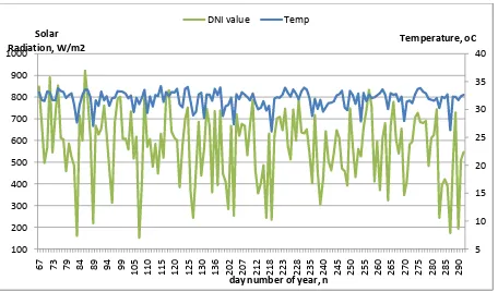
The data for this analysis is recorded from March 2012 to October 2012. The solar radiation change corresponding with the temperature at the solar noon (12pm-3pm) can be seen from the Fig. 2. Solar noon occur at maximum elevation angle which is the highest point of the solar arc. Thus, the solar radiation value is also the highest during that time.
The graph shows that the solar radiation is proportional to the temperature as the Ho value is increase with increasing temperature. This shows that temperature can be used for solar radiation estimation. The graph shows that most of the measured solar radiation value is above 400W/m2. The measured solar radiation value fluctuates might be due to the unpredictable presence of cloud that can obstruct the estimation of solar radiation value by the Pyranometer or the weather changes.
Fig.10: Relationship between Temperature and DNI value.
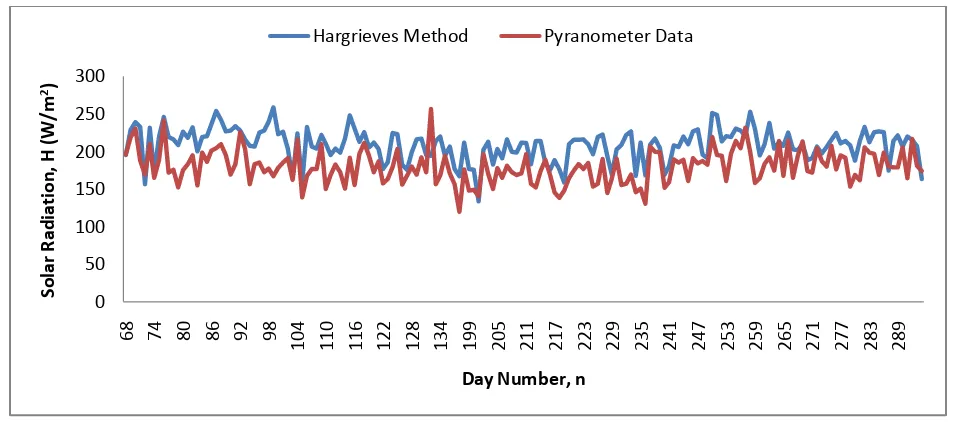
18 Fig.11: Solar Radiation data for Hargreaves Method and Pyranometer Apparatus.
The daily measured data is analyses and plotted into graph of the measured and estimated solar radiation values versus day number. Fig. 3 shows the estimated and measured solar radiation value for different day number. The daily average estimated solar radiation is 180.055W/m2while the average measured solar radiation is 209.00w/m2. The highest estimated solar radiation is 258.83 W/m2 estimated on 8 April 2012. The highest measured solar radiation is 256.52W/m2 measured on 11 May 2012.
The solar radiation value estimated by using Hargreaves method is compared to the daily solar radiation data measured by using Pyranometer is expressed by the value of CRM, RMSE, r2, and EF in Table 2. The determined CRM value is -0.3664 which indicate that the Hargreaves method data is over-estimated the measured solar radiation. This is maybe due to the seasonal climate change of the location and technical problem occurred to the apparatus.
The value of RMSE is 61.56% indicates that there are large difference between the estimated data and the measured data. The determined r2 value of this analysis is -0.71. Efficiency close to 1 indicates the perfect match between the estimated data to the measured data. The EF of the analysis is small, -14.77%which shows that the measured data is better predictor than the evaluated data.
Table 2: Validation of daily measured and estimated solar radiation data.
Validation CRM RMSE r2 EF
-0.3664 61.56% -0.71 -14.77%
The data validation proves that the estimated solar radiation value is higher than the measured solar radiation. This is might be affected by the presence of the cloud where it is usually only
![Table 1: Comparison between four types of CSP technologies[10], [19–24].](https://thumb-ap.123doks.com/thumbv2/123dok/521369.59837/10.612.67.536.122.277/table-comparison-types-csp-technologies.webp)