Development of a novel fault management in distribution
system using distribution automation system in conjunction
with GSM communication
M. A. M. Hanafiah
*, S. H. Raman, W. N. S. E. Wan Jusoh
M. R. Ab. Ghani, Z. A. Baharudin
aFaculty of Electrical Engineering, UniversitiTeknikal Malaysia Melaka (UTeM), 76100, Durian Tunggal, Melaka, Malaysia
Abstract
The paper develops and implements a novel fault management in distribution automation systems (DAS) at low voltage to enhance reliability of power for the consumers. The proposed fault management system is design based on GSM (global system for mobile) communication. The system has been equipped with current sensor as field data interface devices, microcontroller as remote terminal unit, GSM as communication network, computer as master terminal unit and visual basic as human machine interface (HMI) software. A fault management strategy is also designed to find out the fault location effectively without human intervention after a fault occurred. The laboratory results are compared with the simulation results to make the final conclusion on the functionality of the algorithm.
Keywords: Distribution automation system, human machine interface, low voltage distribution system, GSM communication
1.Introduction
The distribution network is a main element of the total electrical supply scheme as it provides the final link between the bulk transmission systems and the customers. It has been reported that 80% of the outages that occur at customer service are due to failures in distribution networks [1]. These problems can be solved by implementing the DAS in distribution side. DAS has been defined by the IEEE as systems that enable an electric utility to monitor, coordinate, and operate distribution network component in real-time mode from remote control centers [2]. Normally, DAS is equipped by intelligent electronics devices (IEDs) that function to automatically monitoring, protecting and controlling switching operations to restore power to consumer during fault.
Fault management system is a crucial process in the operation of the distribution networks. It is assigned to return the network from the fault state back to normal operations. This process involves three discrete phases such as outages alarm, fault location, fault isolation and power supply restoration. Electrical fault usually occur due to failure of insulating media between a live conductors and or between a live conductor and earth. This breakdown may be caused by any one or more factors, for example, mechanical damage, overheating, voltage surges, ingress of a conducting medium, ionization of air, deterioration of the insulating media due to an unfriendly environment or old age, or misuse of equipment. Fault current release an enormous amount of thermal energy, and if not cleared quickly, may cause fire hazards, extensive damage to equipment and risk to human life [3]. Because of that, this paper only focuses to manage the fault current only. When the current supply exceeds the higher rated interrupting current, relay will automatically cut off the power systems. Hence, it can prevent the damage of DAS
* Manuscript received June 13, 2013; revised July 31, 2013.
equipments.
Automation systems are usually related with instrumentation and control. Data acquisition in control system is usually accomplished by placing sensors close to the actual equipment and then transferring the data via communication network to the rear end processing system [4]. Figure 1 show the different communication networks that can be used for DAS applications. Compare wire and wireless systems, wireless is more relevant to be implemented nowadays. It is because wireless network has flexibility function that does not require operators to be in the actual area. Operators can control and monitor DAS in long distance. Among all the communication networks, GSM communication is used. It is because GSM network has low transmission bit error rate, low cost, wide signal coverage and high level of security [3]. GSM network is used in many applications such as health monitoring, meteorological monitoring, decentralized renewable energy plants, remote photovoltaic (PV) water pumping system and so on[5]-[13].
Fig. 1. Distribution automation communication technology options [3].
The problem often faced by distribution substation systems required a longer time to restore back the electric supply when power outage occurred. The engineer and technician have to manually locate the fault position and spend plenty of time [14], [15]. In order to improve reliability, this paper proposed the idea to implement DAS for distribution side. The system will trigger the relay to cut off the supply when detecting fault to prevent the load damage and the human machine interfaces (HMI) will display the alarm to alert the operator. This paper only focuses on the overcurrent fault due to the high impact result when it occurs. Although the fault management systems are useful, the maintenance crews are still needed to fix the faulty distribution branches. Therefore, this paper integrates the GSM communication interface in this system to reinforce their capability. Experimental results demonstrate the validity of the proposed system.
2.Proposed Fault Management System
2.1. System design requirement
microcontroller act as field device interface that transfer the information it gets from the current sensor to personal computer by converting the information to a form that is compatible with the language of the systems. Then, microcontroller must be able to convert electronic signals that received from field devices using communication protocol to transmit data over GSM communication channel. Current sensor will act as the measurement devices that provide information that can inform the operator the performance of DAS. The protection relay will act as the field devices to cut the supply when current is detected to be approximately higher than the rated interrupting current. GSM modem functions as a communication media that do not require a physical link between the transmitter and the receiver to transfer data to and from different sites. Master station unit (MTU) is consists of a personal computer that provides HMI software to the systems. MTU is use to process the information from and sent to the RTU sites and display the current situation to the operator in real time. Visual Basic software is used to develop the HMI for the system because it is more flexible to design the layout based on the systems requirement and low cost compared to other HMI software packages. The overall concept of the system is shown in Figure 2.
Fig. 2. Concept of DAS based on GSM communication system.
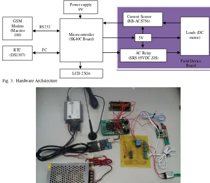
2.2. Hardware design
Figure 3 shows the hardware architecture of the proposed systems. It is consist of microcontroller, current sensor, real time clock (RTC), AC relay, DC motor, LCD display, GSM modem and power supply.
PIC16F877A is the common product of microcontroller which has been manufactured by Microchip. The advantages of these types of microcontroller are low price, broad application and high quality. It is chosen because it can support seven ports of analog of digital converter (ADC) channel which is required for monitoring operations. It also consists of universal asynchronous receiver transmitter (USART) that is use for the GSM network connection. The SK40C board which is designed by Cytron that consist of voltage regulator that convert the power supply from 9 V to 5 V. This is because the operating voltage of the PIC is 5 V. This board is designed as such to be connected with PIC socket with 5V supply.
The BB-ACS756 current sensor is chosen for the systems. The sensor is integrated with Hall Effect to measure the current that flow through the load which is a DC motor. It is very useful for overcurrent fault protection. This sensor is power up with 5 V supply and gives out voltage to indicate the direction and current value.
The RTC is used to set actual time operation that function as a timer to the microcontroller. RTC used in this architecture is DS1307. The advantages of this type of RTC is it could keep track of the time even the power supply is cut off because it has a 3 V backup battery supply.
In conjunctions to cut off the power supply when fault current is detected, AC relay is used. SRS 05VDC-SH is the type of AC relay used in this systems. This relay is a single pole double throw type of relay that operates with maximum voltage of 5VDC and current of 3 A. DC motor is used to act as the load for the systems. When the current sensor detect the current flow through the loads approximately higher than the rated current, the fault will occur, so the system will automatically cut off the supply to
prevent the damage of the DC motor.
For the display unit, the LCD 2X16 is used. It can displays 16 characters per line and it has two rows. This LCD can only displayed the maximum of 32 characters. It is used to display the microcontroller activities to acknowledge the user the current operation that occur in the real time.
PIC16F877A is connected to GSM modem through RS 232 cable with MAX232 converter. This system uses the GSM modem brand Meastro 100. It can be easily controlled by using AT command for all kinds of operations. It also supports GPRS Class 10 for hi-speed data transfer which is about 36Kbps for download speed and 24 kbps for upload speed.
Fig. 3. Hardware Architecture
Fig. 4. Circuit of the system
2.3. Software design
Based on the Figure 5, it shows the flowchart to indicate the sequence process were determined with the visibility of all the DAS equipment. The logic programming is based on this flowchart and C language is used. For this system it consists of two benchmark value which is the higher rated interrupting current (set approximately the rated short circuit current) is 600A and the lower rated interrupting current (set the minimum recovery current) is 12A [16]. First step is to check the power input whether it is turned on or turned off. If not, turned on the power supply and the system can be operated. Then, there are two modes of operations which are automatic mode and manual mode. If manual mode is selected, when fault occur, the process to turn off the relay is done manually by the operator. Besides that, when automatic mode is
selected, the system will go to the normal mode. Normal mode will trigger when branches current is smaller than 600A. So, the relay (normally close-NC) will energized and open the circuit. After that, when branches current exceeds 600A, the system will go to the fault mode. In this state, microcontroller will send a signal to automatically turn off/de-energized the relay (normally open-no) and transmit the information through the GSM network to trigger the alarm in Visual Basic interface that act as HMI software. After the fault occurred, the systems will be in the repair mode. The systems will be back to normal condition when the branches current smaller than 600A but larger than 12A. So, microcontroller will transmit the data to the Visual Basic interface to turn off the alarm. Table 1 shows the summarized of the most frequently AT commands that used for system implementations. AT commands are used to control functionality of GSM modem. Two modes can be implemented to give commands to GSM modem such as Protocol Description Unit (PDU) and text mode [6]. In this paper, text mode is chosen because it is easier to understand and implement compared to PDU mode.
Table 1. List of AT commands
AT Command Meaning
AT Check if serial interface and GSM modem is working
+CMGS Send message
+CMSS +CNMI +CMGF=1 +CMGL +CMGD +CNMA
Send message from storage New message indications Set modem in text mode Read messages Delete messages
New messages acknowledgement
3.Results and Discussions
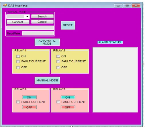
The result of this method will be displayed on the HMI interface. As shown in Figure 6, it is consists of serial port part which is used to make sure the GSM modem 2 is successfully connected with personal computer. Then, the operators need to select the option mode to run the system whether in automatic or manual. When the automatic mode is activated, the relays will automatically turn off when the current that pass through the loads is larger than the higher rated interrupting current. Then alarm box will tell the operator that fault current is occurred and microcontroller will automatically cut off the power supply through relay. If the manual mode is selected, the alarm will trigger automatically when the fault current is occurred. But the operators need to turn off the relay manually through the HMI interface.
Fig.6. Visual Basic Interface
4.Conclusions
This paper is contributed to the novelty for the fault management systems in DAS. As there are many reports that highlighted the most of power interruption are due to the failures in distribution branches. They need the repair teams along the distribution branches to find out the fault location and of course this process consumed plenty of valuable times. The development system was designed to detect the fault location and cut off the power supply before the fault can damage the loads. The operating system described here is capable to identify the fault location automatically and effectively. Hence, the time can be tremendously reduced for the faults detection and restoration.
Acknowledgements
The author thank to the Ministry of Science, Technology and Innovation (MOSTI), Ministry of Higher Education (KPT), Government of Malaysia and the Universiti Teknikal Malaysia Melaka (UTeM) for the support and assistance given to this research.
References
[1] Su CL, Teng JH. Economic evaluation of a distribution automation project. IEEE Transaction on Industry Application Project, 2007; 43(6):1417-1425.
[3] Northcote-Green J, Wilson R. Control and Automation of Electrical Power Distribution Systems. New York: London ;2007. [4] Gungor VC, Lambert FC. A survey on communication networks for electric system automation. Computer Network, 2006
50(7):877-897.
[5] Shariff F, Rahim NA, Ping HW. PV remote monitoring system based on GSM. Presented at: Power and Energy Conversion Symposium, 2012.
[6] Salvadori F, De Campos M, Sausen PS, R.F. De Camargo RF, Gehrke C, Rech C, Spohn MA, Oliveira AC. Monitoring in industrial systems using wireless sensor network with dynamic power management. IEEE Transaction on Instrumentation and Measurement, 2009; 58(9):3104-3111.
[7] Sandro CSJ, Paulo CMC, Fabio TB. A low cost concept for data acquisition systems applied to decentralized renewable energy plants. Open Access, Sensors, 2011; 11(1):743-756.
[8] Rosiek S, Batlles FJ. A microcontroller-based data-acquisition system for meteorological station monitoring. Energy Conversion and Managemet, 2008; 49(12):3746-3754.
[9] Mahjoubi A, Mechlouch RF, Brahim AB. A low cost wireless data acquisition system for a remote photovoltaic (PV) water pumping system. Open Acess, Energies, 2011; 4(1):68-89.
[10] Chandra S, Kar S, Srinivasulu A, Mohanta DK. Distribution system automation based on GSM using programmable system on chip (PSOC). Presnted at: International Conference on Sustainable Energy and Inteligent System, July 2011.
[11] Goel A, Mishra RS, Gupta R. GSM based health monitoring system. BSSS Journal of Computer, 2009; 1(1):37-44. [12] Goel A, Mishra RS. Remote data acquisition using wireless-SCADA system. BSSS Journal of Computer, 2009; 1(1):98-103. [13] Pandya V, Shukla D. GSM modem based data acqusition system. International Journal of Computational Engineering
Research, 2012; 2(5):1662-1667.
[14] Raman SH, Ab. Ghani MR, Baharudin ZA, et al. The implemetation of fault management in distribution system using distribution automation system (DAS) in conjunction with SCADA. Presnted at: Power and Energy Conversion Symposium, 2012.
[15] Ahmed MM, Soo WL, Hanafiah MAM, Ghani MRA, Customized fault management system for low voltage (LV) distribution automation system. In: by Zhang W editor. Fault Detection. 2010.
![Fig. 1. Distribution automation communication technology options [3].](https://thumb-ap.123doks.com/thumbv2/123dok/530771.61364/2.544.74.488.219.422/fig-distribution-automation-communication-technology-options.webp)