A SIMULATION STUDY OF RAILWAY VEHICLE DYNAMICS PERFORMANCE
IBRAHIM BIN TALIB
SUPERVISOR DECLARATION
“I hereby declare that I have read this thesis and in my opinion this report is sufficient in terms of scope and quality for the award of the degree of
Bachelor of Mechanical Engineering (Automotive)”
Signature : ...
Supervisor : EN. MOHD HANIF BIN HARUN Date : ...
A SIMULATION STUDY OF RAILWAY VEHICLE DYNAMICS PERFORMANCE
IBRAHIM BIN TALIB
This report is submitted in partial fulfillment of the requirement for the Bachelor of Mechanical Engineering (Automotive)
Faculty of Mechanical Engineering Universiti Teknikal Malaysia Melaka (UTeM)
DECLARATION
“I hereby declare that the work in this report is my own except for summaries and quotations which have been duly acknowledged.”
iii
ACKNOWLEDGEMENT
Marcus Tullius Cicero, a Roman philosopher once said “gratitude is not only the greatest of virtues, but the parent of all others”. Here, I want to express my infinite gratitude to Allah S.W.T for strengthen my religious hence prevent me from give up while facing all these challenging working environment. For my beloved mother, a special thanks from me for giving full support along this industrial training period.
I would like to thank my project supervisor, En. Mohd Hanif Bin Harun for his guidance along this final year project. All of his knowledge and experience as a lecturer as well as a student has been given to me in order to achieve the objective of this final year project. Without his guidance, I won’t be able to successful finish this project. Besides that, I would also like to thank to Universiti Teknikal Malaysia Melaka (UTeM) for the existence of this final year project because it has given me valuable experience for me to become an engineer in the future.
ABSTRACT
v
ABSTRAK
TABLE OF CONTENT
CHAPTER TITLE PAGE
DECLARATION ii
ACKNOWLEDEMENT iii
ABSTRACT iv
ABSTRAK v
TABLE OF CONTENT vi
LIST OF FIGURE ix
LIST OF TABLE xi
LIST OF APPENDIX xii
LIST OF SYMBOL xiii
CHAPTER 1 INTRODUCTION 1
1.1 History of Railway Vehicle 1
1.2 Problem Statement 3
1.3 Objective 3
1.4 Scopes 4
CHAPTER 2 LITERATURE REVIEW 5
2.1 Introduction 5
2.2 Railway Wheelset 5
2.3 Suspension System on Railway Vehicle 10
vii
2.3.2 Semi-active Suspension 15
2.3.3 Active Suspension 20
2.3.4 Semi-active VS Active Suspension System 22
2.4 Skyhook Controller 23
2.5 PID Controller 24
CHAPTER 3 RESEARCH METHODOLOGY 25
3.1 Background 25
3.2 Railway Vehicle Suspension System Modeling 27
3.3 Model Selection 28
3.4 Equation of Motion 30
3.4.1 Vertical Motion 30
3.4.2 Lateral Motion 31
3.4.3 Rolling Motion 32
3.5 Active Suspension 38
3.5.1 PID Controller 40
3.5.1.1 Decoupling Transformation 40 3.5.1.2 Decoupling Transformation Simulink 42 3.5.1.3 PID Controller Control Structure 42 3.5.1.4 Determining Kp, Ki, and Kd Value 43
3.5.2 Skyhook Controller 44
3.5.2.1 Skyhook Controller Control Structure 45
3.5.3 Parameter Assumption 45
3.6 Simulation 47
3.7 System Diagram 47
CHAPTER 4 RESULT AND DISCUSSION 48
4.1 Body Acceleration 49
4.2 Body Displacement 51
4.4 Passive Versus Active 56
4.5 Graph Validation 59
CHAPTER 5 CONCLUSION AND RECOMMENDATION 60
5.1 Conclusion 60
5.2 Recommendation 61
BIBLIOGRAPHY 62
REFERENCES 65
ix
LIST OF FIGURE
FIGURE TITLE PAGE
1.1 The locomotive ofTrevithick, 1804 1
1.2 Maglev train at Japan 1
2.1 Railway wheelset 6
2.2 Kinematic oscillation of a wheelset 7
2.3 Redtenbacher’s formula for the rolling of a coned wheelset on a 8 curve
2.4 Side view of leaf (laminated) steel spring 11
2.5 Example of bogie system 12
2.6 Twin-tube shock absorber configuration 14
2.7 Orifice Based Semi-Active Suspension 18
2.8 Fluid based Semi-Active Suspension 20
2.9 Types of active suspension 21
2.10 Skyhook Controller 23
2.11 General Control System Structure 24
3.1 Flow chart of PSM 1 and PSM 2 26
3.2 Railway vehicle half-car model 29
3.3 Free Body Diagram of half-car model 29
3.4 Free Body Diagram of vertical motion 30
3.5 Free Body Diagram of lateral motion 31
3.6 Free Body Diagram of rolling motion 32
3.8 Free Body Diagram carbody’s force and moment 40
3.9 Decoupling transformation simulink diagram 42
3.10 PID Controller Control Structure 42
3.11 Ziegler-Nichols Method 43
3.12 Free Body Diagram of skyhook system 44
3.13 Skyhook controller control structure 45
3.14 System diagram 47
4.1 Graph of Vertical Acceleration of Carbody VS Time 49 4.2 Graph of Roll Acceleration of Carbody VS Time 49 4.3 Graph of Lateral Acceleration of Carbody VS Time 50 4.4 Graph of Vertical Displacement of Carbody VS Time 52 4.5 Graph of Roll Displacement of Carbody VS Time 52 4.6 Graph of Lateral Displacement of Carbody VS Time 53
4.7 Graph of Left Suspension Deflection VS Time 54
4.8 Graph of Right Suspension Deflection VS Time 55
4.9 Vertical Motion of Carbody for Passive System VS 56 Active System
4.10 Rolling Motion of Carbody for Passive System VS 57 Active System
xi
LIST OF TABLE
TABLE TITLE PAGE
2.1 Semi-active VS Active Suspension 22
3.1 Model Parameter 45
3.2 PID Controller Parameter 46
3.3 Skyhook Controller Parameter 46
LIST OF APPENDIX
APPENDIX TITLE PAGE
A-1 Complete suspension system simulation diagram 69 A-2 Suspension system subsystem simulation diagram 70 A-3 Carbody’s(left) and truck’s(right) vertical forces simulation 71
diagram
A-4 Carbody’s(left) and truck’s(right) roll moment simulation diagram 72 A-5 Carbody’s(left) and truck’s(right) lateral forces simulation diagram 73
B-1 Gantt chart of project outline (PSM 1) 74
xiii
LIST OF SYMBOL
EMS = Electromagnetic suspension EDS = Electrodynamic suspension DOF = Degree of freedom
MR = Magneto rheological
c = Damping coefficient, Ns/m k = Spring stiffness, N/m
f0y = Creep force, N mc = Carbody’s mass, kg mt = Truck’s mass, kg mw = Wheel’s mass, kg
= Vertical displacement, m
= Vertical velocity, m/s
= Vertical acceleration, m/s2 = Lateral displacement, m
= Lateral velocity, m/s
= Lateral acceleration, m/s2 = Angle, degree
F = Force, N
= Hydraulic actuator force, N I = Moment of inertia
1
CHAPTER 1
INTRODUCTION
1.0 Introduction
1.1 History of Railway Vehicle
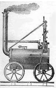
[image:17.612.185.282.517.669.2]Railway vehicle is the most common transportation method to deliver goods and transporting passengers. Ever since an Englishman Richard Trevithick has built the first steam railway locomotive in 1804 as shown on Figure 1.1, the development in rail transportation technology has rapidly increase with the existing of high-speed train powered by magnetic levitation (Maglev Train) on 20th century as shown on Figure 1.2.
When the “father of steam locomotive”, George Stevenson of England built a steam locomotive on 1829, its velocity only reaches 45km/h but nowadays, a maglev train at Japan can reach a velocity of 581km/h. It was about 12 times faster than Stevenson’s locomotive. As train operating speed increases from time to time, safety and comfort was still become a priority for the manufacturer. High-speed train nowadays has been built with the system developed by their engineers to decrease the potential of derailment. On the other hand, comfort on the railway vehicle can be achieved by minimize the effect of vibration and noise occur.
Modern railway vehicle has become faster and efficient, so the mechanical system also becoming more complex. Thus, the system can be better analyze, develop and improve using mathematical and computational approach. Then, a mathematical model is developed and simulated using simulation software. The comfort level of the railway vehicle is improved from the result of model analysis.
Vehicle dynamic which focus on ground vehicle especially automobiles was already become a wider niche that known by people. The reason behind this fact is that automobile is widely used by the people around the world and by using this type of vehicle almost every day, they can feel and learn about dynamic condition of their vehicle. Even their knowledge about automobile was far-out from what other people can think because automotive was such a huge industry and news about it was so accessible. As for the railway vehicle, train or locomotive that usually used for going back to hometown at the weekend or during a festive season, the most obvious thing that we can see different from automobile is it’s moving along a track and its motion is also control by the track direction. The limitation of knowledge about this industry was cause by train and locomotive service and technology in this country that still left-behind if compared to a country such as Japan and France. At Japan, they have the busiest and modern train system while France has TGV which mean high-speed train that can compete with Japan train technology.
3
moves in linear direction, it has longitudinal motion on it. Then, if the train moves in nonlinear direction, as same as automobile the train will have rolling and lateral motion on it. When the train arrives at their station and brake was applied towards it, then of course there will be pitch motion on the vehicle.
1.2 Problem Statement
Railway vehicle was a commonly used transportation system. The movement of the railway vehicle along the track (linear / non-linear) has produced a lot of disturbance e.g. vertical, rolling, lateral motion etc. That disturbance has even more increase for the high-speed railway vehicle and has brought such disadvantages as the railway vehicle stability and passenger comfort has become priority these days. As for this reason, dynamic behavior of the railway vehicle will be analyzed and suitable controller will be design to improve ride handling.
1.3 Objectives
To derive a mathematical model of the railway vehicle model.
To study and analyze the model via equation of motion and simulation process.
1.4 Scopes
The railway vehicle model used to create the mathematical model is a 6-DOF system of a half-car model.
The simulation process was done inside Matlab Simulink.
5
CHAPTER 2
LITERATURE REVIEW
2.0 Literature Review
2.1 Introduction
Engineering have such a various type of niche in the term of its dynamical system and railway vehicle dynamic is one of the most complex systems within it. There is much condition on it that must be count in and put into consideration, such as the contact between the wheel and rail that generate different forces in different kind of speed and the interaction between the wheel and rail that involve complex geometry of both side as we can see flange shape on its wheel.
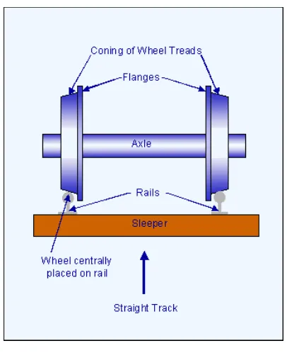
2.2 Railway Wheelset
Figure 2.1: Railway wheelset Source: www.railway-technical.com
On the early years of railway, as the speed of the vehicle was low, they were just focus on reducing rolling resistance so that the load carried can be multiple. Then, further research has been taken out based on more broad aspect as the speed start to be the important thing. The basic shape of the railway wheelset is that it has conical tread and the flange is inside the rail. Though it seems to be a simple design, the fact is such a various design has actually carried out before in order to achieve the design that can roll steady and stable on the rail with a very low potential of derailment.
7
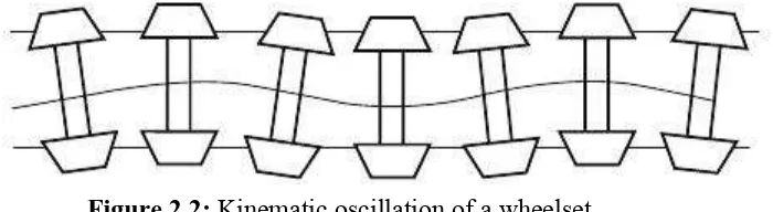
According to George Stephenson (1821) - “It must be understood the form of edge railway wheels are conical that is the outer is rather less than the inner diameter about 3/16 of an inch. Then from a small irregularity of the railway the wheels may be thrown a little to the right or a little to the left, when the former happens the right wheel will expose a larger and the left one a smaller diameter to the bearing surface of the rail which will cause the latter to loose ground of the former but at the same time in moving forward it gradually exposes a greater diameter to the rail while the right one on the contrary is gradually exposing a lesser which will cause it to loose ground of the left one but will regain it on its progress as has been described alternately gaining and loosing ground of each other which will cause the wheels to proceed in an oscillatory but easy motion on the rails.”
[image:23.612.174.524.364.460.2]Stephenson’s description has clearly told us for what is today called kinematic oscillation. This was shown on Figure 2.2 below.
Figure 2.2: Kinematic oscillation of a wheelset
Source: Handbook of Railway Vehicle Dynamics, Google Docs
Figure 2.3: Redtenbacher’s formula for the rolling of a coned wheelset on a curve. Source: Handbook of Railway Vehicle Dynamics, Google Docs
Based on Figure 2.3 above, it show the simple geometric relationship between lateral movement of the wheelset on a curve, y, the radius of the curve, R, the wheel radius, r0,