i
WIRELESS COMMUNICATION APARATUS SYSTEM FOR MEDICAL BED
WAN MOHAMMAD ROSLEE BIN WAN ISMAIL
This report is submitted in partial fulfillment of requirements for the award of Bachelor of Electronic Engineering (Industrial Electronics) with Honours
Faculty of Electronics and Computer Engineering Universiti Teknikal Malaysia Melaka
ii
UNIVERSTI TEKNIKAL M ALAYSIA M ELAKA
FAKULTI KEJURUTERAAN ELEKTRONIK DAN KEJURUTERAAN KOM PUTER
BORANG PENGESAHAN STATUS LAPORAN
PROJEK SARJANA M UDA II
Tajuk Projek : WIRELESS COM M UNICATION APARATUS SYSTEM FOR M EDICAL BED
Sesi Pengajian : 1 0 / 1 1
Saya WAN MOHAMMAD ROSLEE BIN WAN ISMAIL
mengaku membenarkan Laporan Projek Sarjana Muda ini disimpan di Perpustakaan dengan syarat-syarat kegunaan seperti berikut:
1. Laporan adalah hakmilik Universiti Teknikal M alaysia M elaka.
2. Perpust akaan dibenarkan m em buat salinan unt uk t ujuan pengajian sahaja.
3. Perpust akaan dibenarkan m em buat salinan laporan ini sebagai bahan pert ukaran ant ara inst it usi
pengajian tinggi.
4. Sila t andakan ( √ ) :
√ SULIT*
* (M engandungi maklumat yang berdarjah keselamat an atau
kepent ingan M alaysia sepert i yang t ermaktub di dalam AKTA
RAHSIA RASM I 1972)
TERHAD* * * * (M engandungi maklumat t erhad yang t elah dit ent ukan oleh
organisasi/ badan di mana penyelidikan dijalankan)
TIDAK TERHAD
Disahkan oleh:
__________________________ ___________________________________
(TANDATANGAN PENULIS) (COP DAN TANDATANGAN PENYELIA)
iii
I hereby declare that this report is the result of my work except for quotes as cited in the references.”
Signature : ………
iv
“I hereby declare that I have read this report and my opinion this report is sufficient in terms of the scope and quality for the award of Bachelor of
Electronic Engineering (Industrial Electronics) with Honours”.
Signature : ……….
Supervisor Name : ROSMAN BIN ABD. RAHIM
v
DEDICATION
vi
ACKNOWLEDGEMENT
Alhamdulillah….
First and foremost, I would like to take this opportunity to express my grateful to ALLAH because give me a good health and destiny to me finish this project. Praise to Allah S.WT The Most Gracious, The Most Merciful, there is no power no strength save in Allah, The Highest and The Greatest, whose blessing and guidance have helped me through the process of completing this project. Peace and blessing of Allah be upon our prophet Muhammad S.A.W who has given light to mankind
Secondly, I would like to express my warmest gratitude to my supportive supervisors, En. Rosman Bin Abd Rahim and En. Mohd Riduan Bin Ahmad who have provided immeasurable support and guidance toward the completion of my research project. They remarkable ideas and suggestions will be much appreciated in the long run of my career.
My sincere appreciation also goes to my family who has been so tolerant and supportive in all these years either morally or financially. Thanks for their continuous encouragement, love and emotional supports that they had given to me all this while.
vii
ABSTRACT
viii
ABSTRAK
ix
TABLE OF CONTENTS
CHAPTER TITLE PAGE
PROJECT TITLE i
BORANG PENGESAHAN STATUS LAPORAN ii
DECLARATION iii
DEDICATION v
ACKNOWLEDGEMENT vi
ABSTRACT vii
ABSTRAK viii
TABLE OF CONTENTS ix
LIST OF TABLES xiii
LIST OF FIGURES xiv
LIST OF APPENDIXS xvii
1 INTRODUCTION
1.1Project objective 1
1.2Problem statement 1
1.3Scope of work 2
1.4Project significant 3
x
2 LITERATURE REVIEW
2.1Introduction 4
2.2Transmitter schematic circuit and block diagram 5 2.3Receiver schematic circuit and block diagram 7 2.4Relay output function schematic circuit 8 2.5Motor relay control schematic circuit/block diagram 9
2.6Circuit component 12
2.6.1 Resistor 12
2.6.2 Integrated circuit (IC) 13
2.6.3 RF module 315mhz 17
2.6.4 RF transmitter module 18
2.6.5 RF receiver module 18
2.7Network setup and the block diagram 19 2.8Peripheral interface controller (PIC) circuit 21 2.8.1 Graphical user interface (GUI) 24
2.9PIC 18f4550 26
2.9.1 Pin PIC 18f4550 26
2.9.2 Block diagram PIC18f4550 28
3 PROJECT METHODOLOGY
3.1Introduction 29
3.2Discussion method 30
3.3Observation method 30
3.4Project execution 30
3.5Process and step progress of project 31
3.6Flow chart explanation 32
3.6.1 Find the circuit 32
xi
3.6.3 Find the component 32
3.6.4 Simulate the circuit 33
3.6.5 Project execution for electronic circuit 33
3.6.5.1Etching 33
3.6.5.2Drilling 35
3.6.5.3Component placement and soldering 36 3.6.5.4Test the circuit 37 3.6.6 Project execution for mechanical part 38
3.7Overall block diagram 39
4 RESULT AND DISCUSSION
4.1Results 41
4.2Hardware overview 42
4.3Achievement in project 43
5 CONCLUSIONS AND SUGGESTIONS
5.1Conclusions 44
5.2Suggestions 44
REFERENCE 45
APPENDIX A 46
APPENDIX B 48
APPENDIX C 50
APPENDIX D 52
APPENDIX E 54
xii
APPENDIX G 59
APPENDIX H 62
xiii
LIST OF TABLES
NO TITLE PAGE
2.6.2 (a) TX-2B IC pin description 16
xiv
LIST OF FIGURES
NO TITLE PAGE
2.2 (a) Transmitter circuit 5
2.2 (b) Transmitter block diagram 6
2.3 (a) Receiver circuit 7
2.3 (b) Receiver block diagram 7
2.4 Relay output function 8
2.5 (a) Simulation operation of motor control 9 2.5 (b) Illustrates the motor operation when a signal is
received from the receiver circuit 11 2.6.2 (a) Transmitter tx-2b block diagram 13
2.6.2 (b) Receiver rx-2b block diagram 14
2.6.2 (c) Transmitter and receiver ic pin configurations 15
2.6.4 Rf transmitter module 18
2.6.5 Rf receiver module 18
2.7 (a) Wireless router will communicate with wireless adapter to make connection with pic circuit trough ip address 19 2.7 (b) General connection between wireless adapter and pic
xv
2.7 (c) The detail of connection between wireless adapter and
pic circuit 20
2.8 (a) Pic circuit 21
2.8 (b) Pic c compiler software 22
2.8 (c) Usb icsp pic programmer 23
2.8 (d) Microchip pickit 2 programmer software 24 2.8 (e) Block diagram for read/write/erase coding in pic chip 24 2.8.1 (a) Example picture of the delphi7 software 25 2.8.1 (b) Interface for medical bed controller 25
2.9 Pic18f4550 26
2.9.1 Pin descriptions of pic18f4550 27
2.9.2 Block diagram pic 18f4550 28
3.5 Flow chart of process development 31
3.6.5.1 (a) Print the design on the photo paper. use iron to stick
the printed layer design on to pcb board. 34 3.6.5.1 (b) Using iron to stick the printed layer design on to pcb board 34 3.6.5.1 (c) Using ferric chloride acid to eliminate the copper according
pcb layout design 34
3.6.5.1 (d) Drilling process to make holes for components placement 35 3.6.5.1 (e) Solder the entire component 35
3.6.6 (a) Mechanical layout design 38
3.6.6 (b) Welding the model 38
3.7 Block diagram for the system design 39 4.1 Block diagram for the changes system design 41
xvi
4.2 (b) PIC circuit and TX with computer connection 42
4.2 (c) RX circuit, relay control output and relay control motor
xvii
LIST OF APPENDIXS
APPENDIXS TITLE PAGE
A Project Planning 47
B RF Receiver/Transmitter Modules 49
C User Manual – RF Transmitter Module 315MHz 51
D RF Receiver Module 315MHz 53
E RF Transmitter Module 315MHz 55
F PCB Layout 57
G Process of the mechanical parts 60
H PIC18F4550 Data sheet 63
1
CHAPTER 1
INTRODUCTION
This chapter will discuss about the project direction and aims in details. All
related issues such as the problem statement, scope of work, and the project
significant will be highlighted.
1.1 Project Objectives
The objectives of the project are:-
i. To design a medical bed system that can be moved wirelessly and
ease to medical staff.
ii. To facilitate users to move bed by using wireless network control.
1.2 Problems Statement
Every electronic bed that is being used in hospital moved from one place to
another place manually by using the human energy. The main idea is to move the bed
by using network control. There are some problems in order to keep this project
2
i. To expand the project with volubility in order to produce positive affect
and also interesting changes.
ii. To combine RF circuit with PIC circuit and to make the connection
between router and PIC wirelessly.
1.3 Scopes of Work.
This project is known as “Communication Apparatus System for Medical
Bed”, as it automatically functions using the wireless network control system to
operate without using human energy in order to complete a task. To continue the
development, there are some research have been done. There are three main parts to
complete this development/design:-
i. System design to generate wireless connection
Component or part will be involed are Computer (Server), WIFI
usb adapter, and wireless router.
ii. System design using RF
Component which involved on this part is transmitter and another
for recipient part is receiver. The acceptor circuit (receiver) must
be connected to switch to control four functions, left, right,
forward and backward. For the transmitter circuit must be
connected with the relay control output circuit and receiver and
transmitter use the 9v of Dc voltage supply.
iii. Controller Circuit using PIC
Design and development of the system controller using PIC
Transmitter circuit is used to transmit the signal to receiver circuit at 315MHz
frequency (optional). The relay circuit is designed to simplify the control process
which is to avoid damage at the control circuit. The control circuit PIC is connected
3
1.4 Project Significant.
For the project, can be able to use this equipment especially in the hospital
sector; consumer can use this equipment to bring and move patient from one place to
another place wirelessly.
1.5 Thesis Outline.
This thesis is divided into five chapters. In chapter 1, an introduction of
project is presented along with the project objective, scope of this project and the
expected outcome for this project. Chapter 2 is begin with the literature review the
previous project or thesis that related with this project. Then in this chapter also
provides a review on the research of the components and software that have been
used in this project. Chapter 3 discusses the methodology and approach that used to
develop this project, and chapter 4 discusses the result and discussion. The last
chapter summarizes this project, discusses of this project and suggests possible future
4
CHAPTER 2
LITERATURE REVIEW
2.1 Introduction
Literature review was carried out throughout the whole project to gain
knowledge and skills needed to complete this project. The main sources for this
project are the previous project and thesis that is related to this project. And the other
sources are books, journals and articles obtained from Internet. So this chapter
discusses the projects and theses related to this project.
Therefore, by analysis the project did by other researchers, there is a
possibility to know what features are lacking in their projects. It is very important to
improve and to develop a successful project. This project also will recommend some
future works that could be done to improve the same project. So there are some
useful ideas that can be implemented in this project from other similar projects.
Besides that, when reviewing the previous works or project a proper expect
how this project can be conducted and the features that have to be added to make this
project reliable and marketable are enlightened. By reviewing the previous works or
project also have been referred to carefully before kick start this project to produce a
better and more relevant system to the targeted market. Then, the theories and related
knowledge are also important matter to develop this project. It has been acquired and
5
2.2 Transmitter Schematic Circuit and Block Diagram
Figure 2.2 (a): Transmitter circuit
The RF transmitter is used to transmit the signal to the RF receiver circuit by
using the transmitter control module. The antenna will transmit and synchronized the
6
Figure 2.2 (b): Transmitter block diagram.
Figure 2.2(a) and figure 2.2(b) shows the transmitter schematic circuit and
block diagram for the RF operation. 9V DC is supplied as an input to the voltage
regulator. The voltage regulator (LM7805CT) will convert the 9V DC supply to 5V
DC supply. 5V DC supply is then use to activate the Integrated Circuit (IC)
7
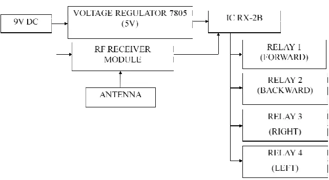
2.3 Receiver Schematic Circuit and Block Diagram
Figure 2.3 (a): Receiver circuit.
The RF receiver circuit is use to receive a signal from the transmitter antenna
by the RF receiver module. The received signal will be send to the IC RX-2B. The
IC RX-2B IC will trigger the relays coil to provide an output function circuit to
operate the motor. [5]
[image:24.612.147.510.134.287.2] [image:24.612.183.504.460.636.2]