I/We* have read this thesis and from my/our* opinion this thesis is sufficient in aspects of scope and quality for awarding
Bachelor of Mechanical Engineering (Automotive)
Signature : ……….
Name of Supervisor : MR. NOREFFENDY BIN TAMALDIN
DESIGN ANALYSIS AND SIMULATION OF A RAILING SYSTEM SECURITY CAGE AT TAMAN BUAYA
AHMAD NOH BIN SALLEH
A report submitted in partial fulfilment of the requirements for the award of the degree of Bachelor of Mechanical Engineering (Automotive)
Mechanical Engineering Faculty Universiti Teknikal Malaysia Melaka
ii
“I declare that this report is the result of my own research except as cited in the references”
iii
ACKNOWLEDGEMENTS
I would like to take the opportunity here to express my appreciation to those who have helped me a lot in completing this research. First of all, I would like to thank my project supervisors, Mr. Noreffendy Bin Tamaldin and Mr. Herdy Rusnandi for their guidance and advices.
iv
ABSTRACT
v
ABSTRAK
Satu pentas pertunjukan menyerupai stadium mini yang merangkumi sistem pagar yang rapi telah dibina di Taman Buaya, Ayer Keroh pada tahun 2009. Keseluruhan system pagar ini terdiri daripada penahan sangkar, penahan tangan, dan juga pagar hiasan telah dipasang sebagai cirri keselamatan dan harus dipantau untuk mengelakkan kemalangan yang tidak diizinkan dari berlaku. Walaupun daya maksima kekuatan tegangan tidak melebihi kekuatan alah bahan, nilai faktor keselamatan di bawah 2 dianggap tidak selamat untuk kebanyakan binaan. Kegagalan fungsi struktur adalah nyata apabila nilai kekuatan tegangan melebihi kekeuatan alah bahan. Suatu kaedah unsur terhingga serentak dengan simulasi pengiraan telah dijalankan untuk mengkaji ciri-ciri penahan sangkar yang dikenakan daya dan juga untuk memahami ciri-ciri penyambungan pada tiang sokongan. Berdasarkan data yang tersedia, keputusan yang diperolehi daripada perisian analisis tidak sejajar telah dibandingkan dengan hasil keputusan analisis struktur untuk menentukan ketepatan hasil perisian dan juga faktor keselamatan untuk bahagian yang kritikal pada penahan sangkar dihisab bagi menyediakan maklumat analisis kekuatan untuk rujukan masa hadapan. Dari keputusan tersebut,didapati kaedah unsur terhingga mampu memberi keputusan yang jitu untuk menganalisa sifat sistem pagar.
vii
CHAPTER TITLE PAGE
CHAPTER 2 LITERATURE REVIEW
2.1 Definitions 5
2.1.1 Classification of Structures 6
2.1.2 Beams 7
2.5 CATIA – Finite Element Analysis
Software 15
2.5.1 Part Design 15
viii
CHAPTER TITLE PAGE
2.6 Research Study 19
2.6.1 “Finite Element Analysis of Structural Steelwork Beam
to Column Bolted Connections” 20 2.6.2 “Finite Element Analysis of
Structural Steelwork Connection On Minor Axis
Using LUSAS Software” 22 2.6.3 “Behaviour of Flush End-Plate
Connection Connected to
Column Flange” 22
2.6.4 “Nonlinear Response of Bolted
ix
CHAPTER TITLE PAGE
3.3.3 Materials 28
3.4 Railing System Loads and Calculations 30 3.4.1 Calculations for Post Design 30 3.4.2 Calculations for Rail Design 32 3.5 CATIA Analysis procedures 34
CHAPTER 4 RESULTS ANALYSIS AND DISCUSSION
4.1 Introduction 36
4.2 Discussion 40
4.2.1 Stress Comparison 40 4.2.2 Post’s size effect on safety factor
and cost 41
4.3 CATIA Analysis Strength and Weakness 44
x
LIST OF TABLES
TABLE NO. TITLE
PAGE
3.1 Details of construction drawings 28
3.2 Material properties used in analysis 28 4.1 Load Case 1 computation analysis results 36 4.2 Load Case 2 computation analysis results 37 4.3 Load Case 3 computation analysis results 38 4.4 Stress comparison for uniform loading on
railing system 40
4.5 Tabular data for steel angle’s safety factor from
xi
LIST OF FIGURES
FIGURE NO. TITLE PAGE
1.1 The phases in design analysis for this project 2
2.1 Commonly used structural forms 6
2.2 Beams 7
2.3 Plane frame and space frame 8
2.4 Indeterminate structure 9
2.5 Finite element types used in LUSAS modeling 20 2.6 LUSAS model of extended end plate connection 21
3.1 A flow chart of the overall study 26
3.2 Railing system dimensions and loads 30
4.1 Maximum Von Mises Stress analysis
result in Load Case 2 37
4.2 Maximum Von Mises Stress analysis
result in Load Case 3 39
4.3 Global maximum location for Von Mises Stress
and displcament in Load Case 1 40
4.4 Maximum von mises stress for the
actual size of steel angle 43
4.5 Maximum von mises stress for the
xii
LIST OF SYMBOLS
g - Gravitational acceleration - Yield strength ASTM - American Society for Testing and Materials
xiii
LIST OF APPENDICES
NO. TITLE PAGE
A Minimum Design Loads for Buildings
And Other Structures 52
1
CHAPTER 1
INTRODUCTION
1.1 General
A structure refers to a system of connected parts used to support a load. Important examples related to civil engineering include buildings, bridges and towers; and in other branches of engineering, ship and aircraft frames, tanks, pressure vessels, mechanical system, and electrical supporting structures are important. Substructure and superstructures used concrete and steel reinforcement to complete the system. It shows that these elements are very important. So, in order to make analysis and design a structure, structural steel must be considered as the main construction materials.
2
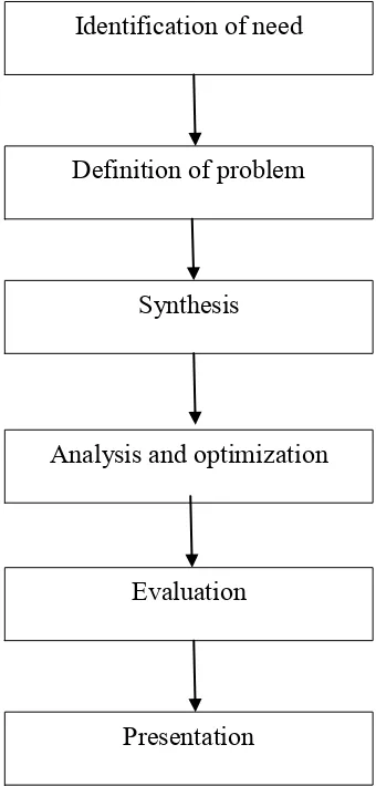
Figure 1.1 : The phases in design analysis for this project
1.2 Problem Statement
It is of interest to have durable structures with long life and low maintenance cost in consideration of safety aspects. Nowadays, in Malaysia, safety railings is the best options to safeguard people from area prone to danger. Manufacturers provide different barrier security products to the areas according to the necessity. Machines are guarded by safety machines guards, from uv light, flying debris, smoke and heat.
Identification of need
Definition of problem
Synthesis
Analysis and optimization
Evaluation
3 This safety railing system prevents people from getting easy access to hazardous areas, thus it is a work area protection.
Based on the situation at a show stage at Taman Buaya, Ayer Keroh, Melaka, the railing system cage that is being built to hold dangerous reptiles during a show, a detailed design analysis and simulation upon the existing railing system has to be done before the show stage is opened to public in order to optimize its safety and reliability. Within this research, it will help to identify the weakness of the system to prevent unexpected misfortunes in the future and thus providing data on the strength of the system.
1.3 Objectives of Study
4 1.4 Scopes of Study
The scopes of the study are:
i. Structural analysis of cage railings.
ii. Analysis and simulation of cage rails at the performing stage by using CATIA Finite Element Method software.
iii. Provide analysis of data for future reference.
5
CHAPTER 2
LITERATURE REVIEW
2.1 Definitions
6 2.1.1 Classification of Structures
All structural forms used for load transfer from one point to another are 3-dimensional (3-D) in nature. In principle one could model them as 3-D elastic structure and obtain solutions like response of structures to loads by solving the associated partial differential equations. Most commonly used structural forms for load transfer are beams, plane truss, space truss, plane frame, space frame, arches, cables, plates and shells. Each one of these structural arrangement supports load in a specific way.
Figure 2.1: Commonly used structural forms
7 2.1.2 Beams
Beams are the simplest structural elements that are used extensively to support loads. They may be straight or curved ones. For example, the one shown in Fig. 1.2 (a) is hinged at the left support and is supported on roller at the right end. Usually, the loads are assumed to act on the beam in a plane containing the axis of symmetry of the cross section and the beam axis. The beams may be supported on two or more supports as shown in Fig. 1.2(b). The beams may be curved in plan as shown in Fig. 1.2(c). It is possible for the beam to have no axis of symmetry. In such cases, one needs to consider unsymmetrical bending of beams. In general, the internal stresses at any cross section of the beam are bending moment, shear force and axial force.
Figure 2.2: Beams
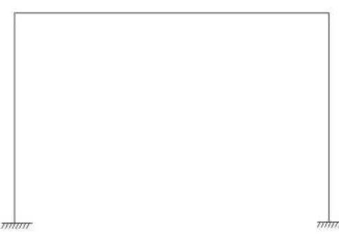
8 2.1.3 Plane Frames
Plane frames are also made up of beams and columns and the only difference is they are rigidly connected at the joints as shown in the Figure 2.3. Major portion of this course is devoted to evaluation of forces in frames for variety of loading conditions. Internal forces at any cross section of the plane frame member are bending moment, shear force and axial force. As against plane frame, space frames members also in Figure 2.3 may be oriented in any direction and there is no restriction of how loads are applied on the space frame. For this project, the cage railing being analyzed belongs to plane frame type as the joints are welded together and resist rotation. They are typically statically indeterminate.
Figure 2.3: Plane frame and space frame
9 2.1.4 Static Indeterminacy
The aim of structural analysis is to evaluate the external reactions, the deformed shape and internal stresses in the structure. If this can be accomplished by equations of equilibrium, then such structures are known as determinate structures. However, in many structures it is not possible to determine either reactions or internal stresses or both using equilibrium equations alone. Such structures are known as the statically indeterminate structures. The indeterminacy in a structure may be external, internal or both. A structure is said to be externally indeterminate if the number of reactions exceeds the number of equilibrium equations.
The degree of indeterminacy may be calculated as i = (m + r) – 2j where m stands for members, j for joints and r for unknown reaction components in the structure. For example, the plane frame shown in Figure 2.4 has 3 members, 4 joints and 6 reaction components. Hence, the degree of indeterminacy of the structure is i = (15 x 3 + 6) – (4 x 3) = 15
Please note that at each joint there are 3 equations of equilibrium for plane frame.
10
2.2 Design Loads
A railing truss, as a structural component of a building, must be designed to support the applied loads that may occur during the life of a building. In addition to dead load, these applied loads are generally live load, snow load, wind load and seismic load. Load intensities are generally specified by a building code. In the absence of a building code, loads and load combinations shall be determined in accordance with acceptable engineering practice as stipulated by the Minimum Design Loads for Buildings and Other Structures (ASCE 7).
2.2.1 Dead Load
Dead load consists of the weight of the truss and material permanently attached to the truss. The actual dead load should be applied on a horizontal projection. Attached materials may consist of sheathing, purlins, insulation, ceiling drywall, and others.
2.2.2 Load Combinations