Virtualisasion of Mobile Core Network by Cloudlet
Communication
Ardian Ulvan*, Robert Bestak#, Davina Olivia*, Melvi*, Gigih FordaNama* *
Department of Electrical Engineering, University of Lampung, Bandar Lampung, Indonesia
#
Department of Telecommunication Engineering, Czech Technical University in Prague, Prague, Czech Republic
[email protected], [email protected], [email protected], [email protected], [email protected]
Abstract
In this paper, a design of network virtualization is built from the end-user to the core network, which includes all the functionality of the network elements. The LTE is assumed as the main core network system, while the 2G/3G/4G systems are as client stations. Testing, measurement and performance analysis are done by developing a testbed of cloud network in the LAN where the access rate is up to 100 Mbps. Subsequently, the traffic loads of 0 Mbps, 10 Mbps, 50 Mbps, 75 Mbps, and 100 Mbps, based on TCP and UDP transport protocols, are generated into the testbed. All elements of the EPC-LTE on this testbed (i.e., HSS, MME, S-GW, P-GW and PCRF) are logically separated from one another in the cloud. Two parameters of Quality of Service (QoS), i.e., jitter and delay, are used as a performance parameter. QoS measurement is performed with two service scenarios, i.e., registration process and basic call (VoIP). Based on the test and measurement it is found that the highest value of jitter and delay are 26.87 ms and 6.53 ms respectively, when loaded network traffic at 100Mbps. From the results, it can be concluded that the network virtualization can be implemented since the EPC elements can be configured in the cloud, and can be accessed through the public IP network.
Keywords: Network virtualization, Telecom Application Server (TAS), cloud network, cloudlet, LTE,
1.
Introduction
The higher need of accessing data and other telecommunication services for mobile users are still limited by the availability of infrastructure due to geographical constraints. Roaming, in both national and international, is still applied and remain a challenge since it costs the user for access and interconnection facilities. One solution to cope with this issue is by a cooperation framework among network operators. Though the shared physical infrastructure with partner operator for roaming users have provided the accessibility and maintain the services, however, the cost is still not reduced significantly.
The recent development of interconnection system in mobile communication has been able to provide the connection between the Base Station Subsystem (BSS) and mobile core network through public access. In legacy system, those network elements are connected conventionally by particular media and interface. In addition, the introduction of all-packet switched system in Long Term Evolution (LTE) technology has provided a capability to virtualize the network. Therefore, the geographical constraint when deploying network elements physically might be solved, by distributing those network elements in a cloud network and providing the user access through a simple public internet access.
Based on our knowledge, there are not so many works in this area. The preliminary concept of network virtualization, which is called Telecom Application Server (TAS), have been developed by Rhino [1] and Aricent [2]. The TAS is a set of telecommunication processes that is built from the core network to end-users. TAS, containing components those are used in the telecommunication system, is designed and optimized for asynchronous communication applications. It implements standard Java application servers (both SIP Servlet and JSLEE) to support, manage and run an operator’s converged services across the Web, IP, and SS7 networks [1]. In addition, TAS also offers a variety of software frameworks and product engineering services to help the network equipment vendors producing applications as well as developing and maintaining TAS features. The reusable software framework can easily integrate existing network architecture across multiple platforms, applications and services. Therefore the system can be provided in a short time with a considerable cost reduction [2].
mobile telecommunications network providing responsive and efficient services [3]. Additionally in [4], a new architecture is introduced in which the user use the technology of mobile virtual machine (VM) to access services through customized software based cloudlet network. Through this cloudlet network, mobile users can access various services, even the service contains within a local area network.
In this paper, the work is focused on the development of virtualized network testbed. It is based on LTE technology, where the clients compose of the traditional 2G access point (e.g., the base station sub-system: base transceiver station – BTS), 3G access system NodeB and 4G’s eNodeB. Meanwhile, the services and applications represent the functionalities of network elements in core network accessed by clients in cloud.
2.
Mobile Core Network
Core Network (CN) is the main part of a mobile telecommunication network that provides various services to the user equipment (UE). CN also manage most functionality of user and control planes in the system. In the 3GPP’s 4G Long Term Evolution system, the CN architecture is known as the System Architecture Evolution (SAE), which has a more simple architecture compared to the previous 2G/3G networks. The SAE is based on all-IP networks that separate the control plane from the user plane traffics, and support multiple heterogeneous access networks [5].
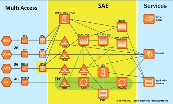
Figure 1. 4G’s Core Network architecture [6]
The main element of SAE is known as Evolved Packet Core (EPC) composed of Mobility Management Entity (MME), Serving Gateway (S-GW), Public Data Network Gateway (P-GW), and Policy and Charging Rules Function (PCRF) sub-elements. A comprehensive CN architecture with multi-access platforms and services is depicted in Figure 1 [6].
In conventional network architecture, a dedicated connection and link should be established between the network access elements and the CN. Moreover, those connections should also be utilized based on particular interfaces, e.g., Abis for 2G, Iu-PS and Iu-Cs for 3G, and S1for LTE. In contrast for 4G, with its all-IP platform, the multi-protocols mobile switching to integrate various multi-access technologies is possible to be supported by the CN through virtualization of CN’s elements, introducing advanced protocol interworking on Home Location Register (HLR)/Home Subscriber Server (HSS) [6], and the deployment of IP Multimedia Subsystem (IMS).
In this work, the design of the network architecture has been specified in an experimental testbed. All CN’s network elements contained in the mobile core network will be connected with BSS devices through a cloud network. In addition, these works also analyze the performance of the signaling mechanisms when a user accesses the network elements that are connected to the core network through the cloud.
3.
The Testbed
The testbed is developed as depicted in Figure 2. The CN’s elements i.e., MME, S-GW, P-GW, HSS, and PCRF have been connected each other in a cloudlet. Those elements are represented by server virtual machines which are assumed located on geographically separated. Two more application servers i.e., VoIP
and Mikrotik are added in order to generate voice over IP traffics and.random traffics respectively. The cloudlet and virtualised environment has been managed by using Proxmox Virtual Environment [7].
Two clients, as depicted in the figure, represented the roaming user equipment (UE), which is assumed to be geographically separated as well. Both UEs are designed to access the CN’s elements to request some LTE’s services through public internet instead of sending request via radio interface. The procedure of attachment into SAE/EPC follows the LTE’s attached procedure as described in [8]. To obtain a real environment, the network will be loaded by packet traffics in various sizes i.e., 0%, 10%, 50%, 75%, and 100% of network capacity. Meanwhile, the maximum capacity of network is set to 100 Mbps. Client 2 is configured as traffic generator.
The simulation on the testbed has been performed in two scenarios as follow:
− Scenario 1: Client 1 performs a registration request to EPC over public internet. The S-GW received and forward the signaling request to other related elements. The traffics are then generated in order to determine the performance of the cloudlet network as well as the characteristic of the virtualised CN’s elements. In this scenario, two QoS parameters are considered, i.e., delay and jitter. The network measurement tool called Iperf [9] is deployed in client 1 to measure those parameters in both TCP and UDP transport protocols. Iperf is also utilised to determine connection performance between each CN’s elements in term of delay and jitter.
− Scenario 2: Client 1 performs a call to a terminal in the network. The call is a Session Initiation Protocol (SIP) based VoIP managed by Asterisk-based IP PBX phone system byTrixBox [10]. A VoIP client software is installed in the client 1. In order to provide a real environment, assigned network traffics are generated by client 2. The QoS performance, in term of delay and jitter, is determined and analysed by using Wireshark packet trace [11] in both UDP and TCP transport protocols. Since this scenario was performed over public network, the tests were done in three different times, in order to obtain a precise average of delay and jitter.
The term QoS is a mechanism that is intended to determine the ability of a network to provide service for the traffic passing through it.The QoS of network refers to the level of speed and reliability of delivery of various types of data load in a communication. There are a number of QoS parameters to
represent the reliability of the network. In this work, the considered delay and jitter are based on ITU-T recommendation G.114 [12] as shown in Table 1.
Table 1. ITU-T standard for delay and jitter
Grade Delay (ms) Jitter (ms)
When it is implemented in the cloudlet network, the CN’s element is assumed can be located anywhere. In case of resource sharing among operators, it can be assumed that any UE can be connected to any operator’s core network elements. It this work, the testbed is designed to adopt that circumstance.
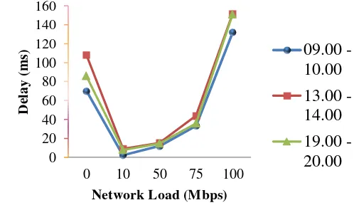
The network performance during registration process is analysed in both delay and jitter. The simulation result in term of delay was measured when Client performed the registration access to S-GW, and when the signalling passed through the cloudlet from one element to another element. The average measured delays and jitter for UDP protocol are depicted in Figure 3 and Figure 4 respectively. The simulation was performed continuously for an hour in three different times i.e., morning (09.00 – 10.00 am), afternoon (01.00 – 02.00 pm), and evening (07.00 – 08.00 pm). Those times represented the peak hours of the network. The delays have been measured by using Iperf software.
traffic load is 100 Mbps. The delay value of 151.53 ms was categorized
Figure 3. Average delay for registration: Client to S-GW (UDP protocol).
0
Figure 4. Jitter during registration process: Client to S-GW (UDP protocol).
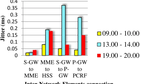
The next test is carried out by measuring the connection access from the S-GW to MME, which is slightly different to the access test from Client to the S-GW. The testing from Client to S-GW is in/out access of core network, as shown in SAE/EPC architecture, which means every user who wants to access the core network will pass through the S-GW as the only EPC network element who deal with the outsiders. In the connection measurement of inter-network elements in the cloud, the generated delays and jitters are measured from the relationship between the entities that have connections as shown in SAE/EPC architecture in Figure 1.Those connection are GW to MME, MME to HSS, S-GW to P-S-GW and P-S-GW to PCRF. The simulation results of measured delay and jitter for inter-network elements which are connected in cloudlet network are depicted in Figure 5 and Figure 6.
As can be seen from the figures, both delay and jitter resulting from the connections between entities was not too big. It is due to the architecture of the testbed. Basically, those network elements are in a server machine, where the servers are installed inside the virtual server host, in which they are virtualised and configured as a cloud. If there are high differences in the results of delay and jitter values, most probably it is due to access speed of the internal network itself. So, the each entity of network elements were communicate only within the scope of the cloud itself, due to the architecture of the testbed. Basically, those network elements are in a server machine. The delay and jitter might be higher if measured in the real cloud network.
0 Figure 5. Delay during registration process: Inter-Network Elements
0 0.05 0.1 0.15 0.2 0.25 0.3 0.35 0.4
S-GW to MME
MME to HSS
S-GW to
P-GW P-GW
to PCRF
Jit
te
r
(m
s)
Inter-Network Elements connection
09.00 - 10.00
13.00 - 14.00
19.00 - 20.00
Figure 6. Jitter during registration process: Inter-Network Elements Connection (UDP protocol).
The following section describes the results and discussion for Scenario 2 when the basic call service, based on VoIP, is implemented and measured in the testbed to analyse the performance of the virtualised network elements.
Basically, VoIP traffic is divided into two network transmission parts i.e., signalling and Realtime Transfer Protocol (RTP) transmissions. Signalling transfer protocol is always based on TCP, whereas The UDP is used for RTP transfer. The signalling is done between TCP ports that are commonly known, H323-based signalling are supposed to use port 1720, while Session Initiation Protocol (SIP) signalling uses port 5060 [13].
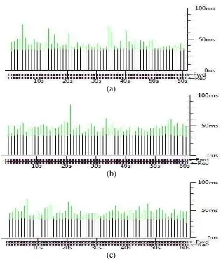
When simulation process took place, Client 1 accessed VoIP services through preinstalled softphone software. In this paper, the simulations were performed by providing traffic load of 0 Mbps, 10 Mbps, 50 Mbps, 75 Mbps, and 100 Mbps. However, only the network traffic load of 50 Mbps is considered for jitter analysis. Packet trace and analysis software, Wireshark, was used to capture the traffic packets, measured and analyse the delay and jitter as shown in Figure 7 and Figure 8 respectively.
From the simulation results as shown in Figure 7, it can be analyzed that the greater value of given network traffic load, the greater value of the measured delay. The time taken for simulation also affected the magnitude of
Figure 7. Delay for basic call service scenario
the delay, it happened due to the high number of users who accessed the internet. The highest value of delay occurred in the afternoon with 100 Mbps of traffic load that is equal to 5.97 ms with a throughput of 0,270 Mbps.
(a)
(b)
(c)
Figure 8. Jitter for basic call service scenario (at 50 Mbps network traffic load): (a) 09.00 – 10.00, (b) 13.00 – 14.00, (c) 19.00 – 20.00.
5.
Conclusion and Further Work
This paper carried the concept of network elements virtualisation based on LTE SAE/EPC core network, and developed a testbed to simulate and proof the concept. The networks elements are designed geographically separated and get connected each other through cloudlet network. Two scenarios i.e., registration process and basic call service have been deployed to measure and analyse the the functionality and QoS testbed. Two QoS parameters are considered i.e., delay and jitter, which are based on ITU.T G 114 recommendation. Based on the simulation result it is found that the highest value of jitter and delay are 26.87 ms and 6.53 ms respectively, when loaded network traffic at 100Mbps. From the results, it can be concluded that the network virtualization can be implemented since the EPC elements can be configured in the cloud, and can be accessed through the public IP network.
Further work is expected to utilise a traffic generator that can support the TCP/UDP protocol simultaneously and providing traffic load corresponding to the maximum capacity of the access rate, so that the simulation can represent the actual state of the network. Moreover, we also concern to deploy the Mean Opinion Score (MOS) or Objective Perceptual Quality Assessment Listeninq (POLQA) based on ITU-T P.863, as the additional paramaters of QoS. The deep investigation on control and user planes functionality in virtualised network elements will also in our further objectives.
Acknowledgement
This works is supported by Directorate General of Higher Education,
Republic of Indonesia, through the International Collaboration Research
Grant. It is also supported by research grant of Czech Technical
University in Prague.
References:
[1]. “Real – time Telecom Application Server”.
http://www.opencloud.com/products/rhino-application-server/real-time-application-server/. Last accessed on June 2014.
[3]. Rodriguez-Martinez, M., Seguel, J., Sotomayor, M., Aleman, J.P., “Open911: Experiences with the Mobile Plus Cloud Paradigm”, in the proceeding of the 2011 IEEE International Conference on Cloud Computing, Washington DC, USA, July 2011. ISSN: 2159-6182.
[4]. Satyanarayanan, M., Bahl, P., Caceres, R., Davies, N., “The Case for VM -Baed Cloudlets in Mobile Computing”, IEEE Pervasive Computing, Vol 8 Issue 4, Dec 2009. pp. 14-23, ISSN: 1536-1268.
[5]. 3GPP TS 33.401, “The 3rd Generation Partnership Project; Technical Specification Group Services and System Aspects; 3GPP System Architecture Evolution (SAE): Security Architecture (Release 8)”, 2009. [6]. Tecore Networks, “iCore® 4G LTE EPC”, can be accessed at
www.tecore.com.
[7]. Proxmox Server Solution GmbH, “Proxmox Virtual Environment: Server -Virtualization with KVM and Containers”, can be accessed at www.proxmox.com/proxmox-ve/ .
[8]. Ulvan, M., Ulvan, A., Bestak, R.,”Network Entry Procedure in Femtocell Network”, in Proceeding of the 2010 Networking and Electronic Commerce Research Conference (NAEC 2010). Dallas, TX: American Telecommunication Systems Management Association Inc., 2010, p. 156-166. ISBN: 978-0-9820958-3-6
[9]. Tutorial Site at www.iperf.fr
[10]. Garrison, K., Dempster, B., “TrixBox Made Easy: A step-by-step guide to installing and running your home and office VoIP system”, Packt Publishing, October 2006, ISBN-10: 1904811930, ISBN-13: 978-1904811930.
[11]. Chappel, L., “Wireshark Network Analysis: The Official Wireshark Certified Network Analyst Study Guide”, Protocol Analysis Institute, db “Chappel University”, 2012. ISBN-10: 1-893939-94-4, ISBN-13: 978-1-893939-94-3. www.wireshark.org.
[12].ITU-T G.114., One way transmission time, http://www.itu-t.int/publications, April 2010.