METAL LINE DETECTION: A NEW SENSORY
SYSTEM FOR LINE FOLLOWING MOBILE ROBOT
1M.Z.A RASHID, 2H.N.M Shah, 3M.S.M Aras, 4M.N.Kamaruddin, 5A.M. Kassim, 6H.I.Jaaafar
1,2,3,4,5,6
Faculty of Electrical Engineering, Hang Tuah Jaya, 75260 Durian Tunggal, Melaka, Malaysia E-mail: [email protected]
ABSTRACT
This paper presents a new type of line following robot that uses metal sensor to detect metal line and maneuver around based on that line. The paper focused on developing the hardware model of automated guide vehicle (AGV) system and integrating it with metal detection sensor. The system performance is measured in a straight line movement and when the robot turns at specific degrees.The metal line following robot can be used to move objects in daily life operation, warehouse operations or manufacturing facility to any desired location automatically. A metal line with certain length can be placed on the desired floor to indicate the path that the robot requires to move. Based on the experimental studies, it showed that the mobile robot can maneuver and track the metal line that is attached on the floor by utilizing three inductive proximity sensor located in front of the robot. This sensory system can be used as alternative sensor instead of using line following sensor which normally based on the infrared proximity detector. The line following robot that operates based on the metal line capable to overcome the problem of different light intensity reflection.
Keywords: Mobile Robot,Metal Line Detection System, Inductive Proximity Sensor,Line Following.
1. INTRODUCTION
In this recent days, many line following robots have beedn designed and utilized either as an education kit or applied in the industrial sectors. This line following robots normally consists of either four wheels, two wheels or single wheel. However, these line following robots normally utilized the infra red sensor, ultrasonic sensors or the camera in order for them to follow the line. Besides, the line for these mobile robots are limited to white and black colors only.
According to the paper by [1], the problem that was faced by their line following robot which was equipped with RGB color sensors are the sensors did not focus on a specific area, and therefore detected the color of the entirefield of view. Another difficulty that was faced by the robot was the continuous change in light intensity of the surrounding environment.
In the next paper,[2] mentioned that line following robot that used black and white color line and detected by infrared ray sensors worked
well if the sensors are shielded from the ambient light which affected the performance of the sensors.
Another mobile robot development by [3] showed that the Light Dependent Resistor (LDR) that received the signal from the Light Emitting Diode (LED) and without LED signal varied. Besides, voltage drop for the LDR with LED condition is higher than the without LED conditiondue to the higher light intensity exposure to the LDR devices. The paper also mentioned that the LDR and LED should be mounted at certain distance and certain angle to obtain the optimum signal.
2. MOTIVATION
of unneeded information by the use of the agents
In another research, [5] had developed a straight-line path following mobile robot without clear landmarks. The differential drive cleaning robot with embedded ultrasonic sensors using a lateral reference distance vector (LRDV) was tested. The study was carried out about the continues to the other area that not surveyed yet and the robot compares the previously clean area to do the cleaning process. This process runs very well when the objects situated in the path lean against the walls and needs some adjustment in vice versa situation.
Next, a position sensing system in autonomous vehicle robot was proposed [6]. This robot is designed based on the idea of position measurement and direction using magnet and magnetic sensor. The magnetic sensor was mounted in the robot to detect the magnetic field produces by magnets. The implementation of magnetic sensing system on roads can be problem due to the level of the background magnetic field is big compared to magnet’s magnetic field. It was changed in a condition regarding with location or the course.
In another project,[7] proposed the development of intelligent line follower mini-robot system. The purpose of this project is to understand and adjust the performance of robot algorithm during its pathway by getting information in real time from different magnetic sensors. The real-time navigation was obtained using an inductive magnetic sensor that shows the position and direction of the pathway. This robot was used a continuous black line on a white background as its pathway.
A line follower was developed by [8] to deliver products from one point to another. This project proposed one of the method that can replaced the rail, conveyor and gantry system method. This robot can detect and follow the black or white line that had drawn on the floor to
white background whether in a straight or curve line. The robot was used differential steering to turn the robot besides can adjust the motors appropriately with the line condition.
In the paper [9],the author used photoelectric sensor to detect the tracking line of the pathway is develops in the path detection of photoelectric intelligent track searching vehicles. The studied was carried out to get the elasticity and stability of the smart vehicle which is related to the accuracy and precision. Intelligent vehicle could be achieved through the advance process of the vehicle movement. It could move in a great condition whether in a straight or curve line if the intelligent vehicle had enough prior information of the its travelling path. The steering engine and motor can be control in order to accelerate and decelerate while turning suitably besides shortening the travelling distance.
Then, a line following robot named as TABAR that been discussed in paper [10]. The purpose of this project was to be use in the line following robots competition. Optical sensor was mounted at the front end of the TABAR robot in order to control position in line. High robustness and resolution was required in development the line sensing as consequences to provide the good controlling speed and steering the robot to track the line.
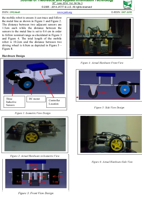
the mobile robot to ensure it can trace and follow the metal line as shown in Figure 1 and Figure 2. The distance between two adjacent sensors are 1.5cm each while the distance between the sensors to the metal line is set to 0.4 cm in order to follow nominal range as elucidated in Figure 3 and Figure 4. The total length of the mobile robot is 10.2cm and the distance between two driving wheel is 6.0cm as depicted in Figure 5 – Figure 8.
Hardware Design
Figure 1: Isometric View Design
Figure 2: Actual Hardware in Isometric View
Figure 3: Front View Design
Figure 4: Actual Hardware Front View
Figure 6: Actual Hardware Side View Three
Inductive Sensors
DC motor
Controller Location
0.4 cm 1 cm
1.5cm
1.5cm
10.2cm
Selection Of Sensor
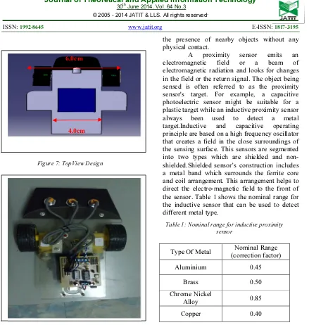
Sensor is a device that can use to detect objects. It responds to an input quantity by generating a functionally based on their output usually in the form of an electrical or optical signal. Basically, the selection of sensor is based on several characteristics. In the development of the line following robot using metal line detection, sensor is a part that has to be taken into consideration to make this project successful. In this line following mobile robot using metal line, a proximity sensor is utilized.
the presence of nearby objects without any physical contact.
A proximity sensor emits an
electromagnetic field or a beam of
electromagnetic radiation and looks for changes in the field or the return signal. The object being sensed is often referred to as the proximity sensor's target. For example, a capacitive photoelectric sensor might be suitable for a plastic target while an inductive proximity sensor
always been used to detect a metal
target.Inductive and capacitive operating
principle are based on a high frequency oscillator that creates a field in the close surroundings of the sensing surface. This sensors are segmented into two types which are shielded and non-shielded.Shielded sensor’s construction includes a metal band which surrounds the ferrite core and coil arrangement. This arrangement helps to direct the electro-magnetic field to the front of the sensor. Table 1 shows the nominal range for the inductive sensor that can be used to detect different metal type.
Type Of Metal Nominal Range
(correction factor)
Aluminium 0.45
Brass 0.50
Chrome Nickel
Alloy 0.85
Copper 0.40
ITEMS FUNCTION
DC Motor To make the wheel
move
Acrylic plastic As the body of line
following robot
Arduino Uno To control the line
following robot
response
Figure 7: TopView Design 4.0cm 6.0cm
Table 1: Nominal range for inductive proximity sensor
Table 2: Components used in the metal line following mobile robot
sensor
Driver motor board To control the electric parts
Switch As a button
Battery 1.5V Power supply
4. SYSTEM TESTING
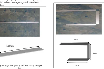
The metal line selected to be used in this metal line following robot is an aluminum line with 25 mm width and 1000mm length. The criteria for testing the sensory system for this robot are divided into a few criterias:
(a) Non-greasy and non-dusty straight line. (b) Non-greasy and non-dusty zig-zag line. (c) Non-greasy and non-dusty curve line. (d) Dusty zig-zag line.
(d) Greasy zig-zag line.
Figure 9 (a) shows the non-greasy and non-dusty straight line while figure 9(b) shows Non-greasy and non-dusty zig-zag line. Another figure, figure 9(c) shows non-greasy and non-dusty curve line.
100cm
Figure 9(a): Non-greasy and non-dusty straight line.
30cm
30cm
40cm
Figure 9(b): Non-greasy and non-dusty zig-zag line.
40cm
30cm
30cm
In order to test the reliability of this sensory system that has been integrated with the metal line following robot, dusty zig-zag line and greasy zig-zag line is chosen and compared with the non-greasy and non-dusty line. Dusty zig-zag line is shown in the Figure 10(a) while greasy zig-zag line is shown in Figure 10(b).
5. RESULTS AND DISCUSSION
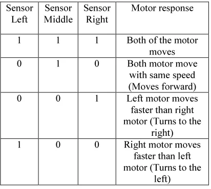
The sensory system used at the metal line following robot has been tested. The speed of the motor has been recorded by using the serial monitor from the arduino controller board used in this system. Initially, the sensor system is set to 0V if the sensor does not receive the signal that is sent to locate the aluminum line. At this
the aluminum line and obtain value of 5V, the motor’s PWM is set to make the motors rotate with full speed which is 255. For instance, if all the sensors detect metal line, both of the motor will move forward. If only the right sensor detect metal line, left motor will move faster than right motor in order to turn the robot to right position. Then, if the left sensor sensor detect metal line, right motor will move faster than left motor in order to turn the robot to left position. Lastly, if middle sensor and right sensor or middle sensor and left sensor detect metal line, the robot will manauver in the forward direction.
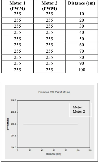
In the first experiment that has been conducted which is a straight line, both motors move with full speed as shown in the Table 3 and Figure 11.
Motor 1 (PWM)
Motor 2 (PWM)
Distance (cm)
255 255 10
255 255 20
255 255 30
255 255 40
255 255 50
255 255 60
255 255 70
255 255 80
255 255 90
255 255 100
Figure 10(a) Dusty zig-zag line.
Figure 10(b) Greasy zig-zag line.
Table 3: Robot’s movement in straight line
Motor 1 Motor 2
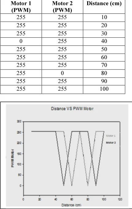
Next experiment that has been conducted is to make the robot move in the greasy and non-dusty zig-zag aluminum line. The performance of the sensor to detect the aluminum line accurately and sends the signal to the controller to move the robot accordingly is tabulated in Table 4. The graph for the right motor and left motor movement is depicted in Figure 12.
Motor 1 (PWM)
Motor 2 (PWM)
Distance (cm)
255 255 10
255 255 20
255 255 30
0 255 40
255 255 50
255 255 60
255 255 70
255 0 80
255 255 90
255 255 100
Another experiment that has been conducted is to identify the performance of the mobile robot to detect the curvature metal line and moves along that line. Table 5 and Figure 13 shows the mobile robot movement along the
curve line in non- greasy and non-dusty environment
.
Motor 1 (PWM)
Motor 2 (PWM)
Distance (cm)
255 255 10
255 255 20
255 0 30
255 255 40
255 255 50
255 0 60
255 255 70
255 255 80
255 255 90
255 255 100
In another figures, Table 6 – Table 8 show the behavior of the mobile robot that moves along the zig-zag metal line with different surface type. The analysis shows that the motors on the robot move according to the algorithm set up previously and this elucidate that the sensors on robot perform perfectly and they are not affected by the surface type.
Table 4: Robot’s movement in greasy and non-dusty zig-zag aluminum line
Figure 12: Graph for robot’s movement in non-greasy and non-dusty zig-zag aluminum line.
Table 5: Robot’s movement in greasy and non-dusty curve aluminum line
sensors on the mobile robot that can follow metal line. This project is purposely done to evalute the performance of the sensors on various kind of environment such as non-dusty, non-greasy, dusty and greasy metal line. It is proven that the inductive sensors are not much influenced by
white line following mobile robot which
normally always influenced by other
environment conditions i.e intensity of light and battery condition. This sensory system is expected to be equipped on the single wheel mobile robot and other mobile robot as mentioned in [12]-[17]
ACKNOWLEDGMENT
The author want to express appreciation to Universiti Teknikal Malaysia Melaka (UTeM) for sponsoring this project. Besides, author also
highlights appreciation to Unmanned
Autonomous Intelligent Research Group (UAIR)
and Centre of Robotics and Industrial
Automation (CERIA) for supporting the project.
7. REFERENCES.
[1]M. Michail, N. Alexandros, and P.Evangelos, “Semi-autonomous Color Line-Following
Educational Robots:Design and
Implementation”, 2011 IEEE/ASME
International Conference on Advanced
Intelligent Mechatronics (AIM2011)
Budapest, Hungary, 2011.
[2] P.Mehran, M. M.Sanaatiyan, M.R.
Ghahroudi,
“
A Line Follower Robot fromdesign to Implementation:Technical issues and problems”, 2011, IEEE.
Table 6: Robot’s movement in non-greasy and non-dusty zig-zag aluminum line
Table 7: Robot’s movement in dusty zig-zag aluminum line
[3] Nasrudin.N, Nur M. Ilis, T.P Juin, T.T.K Chun, L.W. Zhe, F.Z. Rokhani, “Analysis of the Light Dependent Resistor Configuration for Line Tracking Robot Application”, IEEE 7th International Colloquium on Signal Processing and its Applications, 2011. [4] E. Frere, T. Bastos and V. Dynnikov, “An
Agent-Based Ultrasonic Sensing System for Mobile Robots”, 1997, IEEE.
[5] J. Palacin, X. Lasa, S. Marco, “Straight-Line Path Following in Cleaning Robots Using Lateral Ultrasonic Sensors”, May 2003,
lnstrumentation and Measurement
Technology Conference.
[6] Y. Ryoo, Y. Lim, E. Kim, J. Lee, “Design of
Magnet Based Position Sensing for
Autonomous Vehicle Robot”, 2004,
IEEEIRW International Conference on intelligent Robots and Systems.
[7] R. Osorio, J. A. Romero, M. Pena C, I. L. Juarez, “Inteligent Line Follower Mini-Robot System”, 2006, International Journal
of Computers, Communications and
Control.
[8] V. Hymavathi, G. Vijaykumar, “Design and Implementation Of Double Line Follower Robot”, June 2011, International Journal of
Engineering Science and Technology
(IJEST).
[9] H. Xu, X. Guo, C. Ma, C. baowen, “Continuous Path Detection Method of Intelligent Track Searching Vehicle Based on Photoelectric Sensor”, (2010), IEEE. [10] M. Pakdaman, M. M. Sanaatiyan, M. R.
Ghahroudi, “A Line Follower Robot from design to Implementation:Technical issues and problems”, 2010, IEEE
[11]J.Thirumurugan, M.Vinoth, G.
Kartheeswaran, M. Vishwanathan, “Line Following Robot for Library Inventory Management System”, 2010, IEEE.
[12]MZA Rashid, MSM Aras, HNM Shah, WT
Lim, Z Ibrahim, “Design and system parameter's validation of the unicycle
mobile robot”, 2012 International
Conference on Control,Automation and Information Sciences (ICCAIS) Ho Chi Minh, Vietnam 2012
[13] MZ Ab Rashid, SN Sidek, “Dynamic modeling and verification of unicycle
mobile robot system”, 2011 4th
International Conference On Mechatronics (ICOM) Kuala Lumpur, Malaysia 2011.
[14] AM Kassim, MZA Rashid, MR Yaacob, N Abas, T Yasuno , “Effect of Reference Height Control System on CPG Networks
for Quadruped Hopping Robot”, Applied
Mechanics and Materials 313, 498-502, 2013
[15] AM Kassim, MS Jamri, MSM Aras, MZA Rashid , “ Design and Development of Vibration Method for Vehicle Reverse System(VRS)”, Procedia Engineering 41, pp. 1114-1120, 2012.
[16] M.S.M. Aras, S.S. Abdullah, S.S. Shafei, MZA Rashid, A. Jamali, “Investigation and Evaluation of Low Cost Depth Sensor
System Using Pressure Sensor for
Unmanned Underwater Vehicle”, Majlesi
Journal of Electrical Engineering,2012. [17] MSM Aras, AS Mohd Nor, SS Abdullah,
MZA Rashid, “Development of Subsea Altimeter Sensor System (SASS) Using Portable Sonar Sensor Fish Finder Alarm for
Unmanned Underwater Vehicles”,
International Journal on Recent Trends in Engineering & Technology, 8 (2). pp. 110-115. ISSN 2158-5563.
[18] MZ Rashid, TA Izzuddin, N Abas, N Hasim, FA Azis, MSM Aras, “Control of Automatic Food Drive-Through System using Programmable Logic Controller (PLC)” , International Journal of U-& E-Service, Science & Technology,2013.
[19]MSM Aras, MZA Rashid, SS Abdullah, AA
Rahman, MAA Aziz, “Development and
Modeling of Unmanned Underwater
Remotely Operated Vehicle Using System Identification for Depth Control”, Journal of Theoretical & Applied Information Technology,2013.
[20] MSM Aras, SS Abdullah, HNM Shah, MZA Rashid, MAA Aziz, Robust Control of
Adaptive Single Input Fuzzy Logic
Controller for Unmanned Underwater