DEVELOPMENT OF CONTROL ALGORITHM FOR FREESCALE CUP LINE FOLLOWING ROBOT
SUKURI BIN SULO
LINE FOLLOWING ROBOT
SUKURI BIN SULO
This Report Is Submitted In Partial Fulfillment of Requirements for the Bachelor of Electronic Engineering (Industrial Electronic Engineering)
Faculty of Electronic and Computer Engineering Universiti Teknikal Malaysia Melaka
UNIVERSTI TEKNIKAL MALAYSIA MELAKA
FAKULTI KEJURUTERAAN ELEKTRONIK DAN KEJURUTERAAN KOMPUTER
BORANG PENGESAHAN STATUS LAPORAN
PROJEK SARJANA MUDA II
Tajuk Projek : DEVELOPMENT OF CONTROL ALGORITHM FOR FREESCALE CUP LINE FOLLOWING ROBOT
Sesi Pengajian : 1 3 / 1 4
Saya SUKURI BIN SULO
(HURUF BESAR)
mengaku membenarkan Laporan Projek Sarjana Muda ini disimpan di Perpustakaan dengan syarat-syarat kegunaan seperti berikut:
1. Laporan adalah hakmilik Universiti Teknikal Malaysia Melaka.
2. Perpustakaan dibenarkan membuat salinan untuk tujuan pengajian sahaja.
3. Perpustakaan dibenarkan membuat salinan laporan ini sebagai bahan pertukaran antara institusi pengajian tinggi.
4. Sila tandakan ( √ ) :
SULIT*
*(Mengandungi maklumat yang berdarjah keselamatan atau kepentingan Malaysia seperti yang termaktub di dalam AKTA RAHSIA RASMI 1972)
TERHAD** **(Mengandungi maklumat terhad yang telah ditentukan oleh
organisasi/badan di mana penyelidikan dijalankan)
TIDAK TERHAD
Disahkan oleh:
__________________________ ___________________________________
“I declare that this report is the result of my own work except for the summary and the passage that I cited the source.”
Signature : ……… Name : SUKURI BIN SULO
iii
“I hereby declare that I have read this report and in my opinion this report is sufficient in terms of scope and quality for the award of a Bachelor Degree of Electronic Engineering
(Industrial Electronic Engineering).”
Signature : ……….………
ACKNOWLEDGEMENT
v
ABSTRACT
ABSTRAK
Line Following Robot juga diknenali sebagai kereta autonomi adalah reka bentuk
projek untuk bersaing dalam Frescale Cup. Ia mempunyai Line Scan Camera yang
digunakan untuk mengesan keadaan garis hitam di hadapan kereta dan menjejaki garisan tersebut sehingga ke penamat litar. Semua algoritma berkaitan sistem kawalan tersebut akan diprogramkan dalam Freescale 32-bit MCU dengan menggunakan pengaturcaraan C termasuk kawalan motor servo dan dua kawalan kelajuan motor dc untuk kanan dan kiri roda belakang. Walaubagaimanapun terdapat beberapa kekangan reka bentuk ini sebagai contoh kelajuan ini adalah tidak stabil kerana walaupun Pulse Width Modulation
(PWM) telah ditetapkan dari unit MCU tetapi ia masih sepenuhnya bergantung kepada kapasiti bateri di mana ia akan berkurangan mengikut masa. Sensor lain diperlukan yang dikenali sebagai Encoder untuk mengesan kelajuan sebenar roda. Oleh kerana terdapat
saiz dan jenis lengkung yang berbeza dalam litar lumba, Line Following Robot juga akan
direka supaya kelajuan boleh dikawal mengikut keadaan litar. Algoritma akan merangkumi semua sistem kawalan untuk kelajuan roda, pergerakan servo, kamera, dan
Encoder. Semua penyelesaian direka untuk meningkatkan kelajuan Line Following
Robot untuk melengkapi satu pusingan penuh untuk apa-apa jenis litar lumba secepat
vii
TABLE OF CONTENTS
CHAPTER TITLE PAGE
PROJECT TITLE i
DECLAIRATION ii
DEDICATION iii
ACKNOLEDGEMNT iv
ABSTRACK v
ABSTRAK vi
LIST OF CONTENTS LIST OF TABLES
vii viii
LIST OF FIGURES ix
LIST OF ABREVIATIONS xi
LIST OF APPENDICES xii
I INTRODUCTION
1.1 Project Introduction 1.2 Problem Statements 1.3 Project Objectives 1.4 Scope of Work 1.5 Project Methodology 1.6 Report Structure
CHAPTER TITLE PAGE
II LITERATURE REVIEW
2.1 Image processing Using Line Scan Camera (Thresholding)
2.2 Speed Sensor Using Encoder
2.3 Speed Sensor Using Hall Effect Sensor 2.4 PID for servo motor control system 2.5 Steering and DC motor control
8
9 10 11 13
III PROJECT METHODOLOGY
3.1 Project Block Diagram
3.2 Speed Control Algorithm and Encoder Circuit 3.3 Line Scan Camera Algorithm
3.4 Servo Algorithm
3.4.1 The Car Model 3.4.2 The Servo Model 3.4.3 The Time Delay Model
3.5 Overall Line Following Robot algorithm
16 19 23 26 27 28 29 31
IV RESULT AND DISCUSSION
4.1 Line Scan Camera Algorithm 34
4.2 Servo Motor Control System 39
4.3 DC Motor Control System 4.4 Speed Control Algorithm
44 45
V CONCLUSION AND RECOMMENDATION
5.1 Conclusion 50
5.2 Recommendation 51
REFERENCES 52
ix
LIST OF TABLES
No. TITLE
LIST OF FIGURES
No. TITLE PAGE
1.1.1 The Line Following Robot for Freescale Cup 2
2.1.1 Example of Static Thresholding[1] 8
2.2.1 Encoder circuit Diagram[2] 9
2.3.1 Hall Effect Sensor For Speed Detection[3] 10
2.4.1 Bicycle Model [6] 11
2.5.1 Steer Control Algorithm [7] 13
2.5.2 Adaptive Speed Control [7] 14
3.1.1 Line Following Robot Block Diagram 16
3.1.2 FRDM-KL25Z Board [8] 17
3.1.3 FRDM-TFC Board [9] 17
3.1.4 FRDM-KL25Z and FRDM-TFC Boards [9] 18
3.2.1 Speed Algorithm 19
3.2.2 Encoder Circuit (ADC) 20
3.2.3 Flow Chart For Encoder Counting 22
3.2.4 Distance Between Black Strip Measurement 23
3.3.1 Threshold Position 24
3.3.2 Line Scan Camera Algorithm 25
3.4.1 Closed Loop System With PID Controller 26
3.4.1.1 Car Model Parameter L And L' 27
3.4.2.1 Servo Motor Futaba S 3010 Type 28
xi
3.4.3 The P and D Parameters 30
3.5.1 Line Following Robot Algorithm 31
3.5.2 The CodeWarrior Software 32
4.1.1 Sample of Camera Data Stored In 'Linescanimage0[]' Array 34
4.1.2 Camera Data Thresholding Algorithm 34
4.1.3 Cample of Camera Data After Thresholding 34
4.1.4 Start and Stop Part Of The Track 35
4.1.5 Line Position and Line Number Detection Algorithm 35
4.1.6 Line Detection Algorithm 36
4.1.7 One Line Track Type 37
4.1.8 Three Line Track Type 37
4.1.9 Updating Line Data To Servo And DC Motor 38
4.2.1 Transient Response for Kp=10, Ki=0 and Kd=0.9 39 4.2.2 Transient Response for Kp=5, Ki=0 and Kd=0.9 40 4.2.3 Transient Response for Kp=10, Ki=0 and Kd=10 40 4.2.4 Transient Response for Kp=20, Ki=0 and Kd=0.9 41 4.2.5 PID Control System Algorithm For Servo Motor 42 4.2.6 Servo Movement By Using PID Control System 43
4.3.1 DC Motor Speed Selecting 44
4.4.1 Speed Control Algorithm 45
4.4.2 Graph Counting Number Against PWM Value 47
LIST OF ABREVIATIONS
ADC - Analog to Digital Converter
PWM - Pulse Width Modulation
IR - Infra Red
xiii
LIST OF APPENDICES
No. TITLE PAGE
CHAPTER I
INTRODUCTION
2
2.6 Project Introduction
The line following robot is an autonomous robot typically produced for racing contest. By using the vision sensors, the robot will detect and follow the black on the racetrack.
For this project the line following robot is designed to compete in the Freescale Cup introduced by Freescale Semiconductor. In this competition students will build and program an autonomous car by referring the specified characteristics and the fastest car to complete a full round of the racetrack without derailing will be the winner.
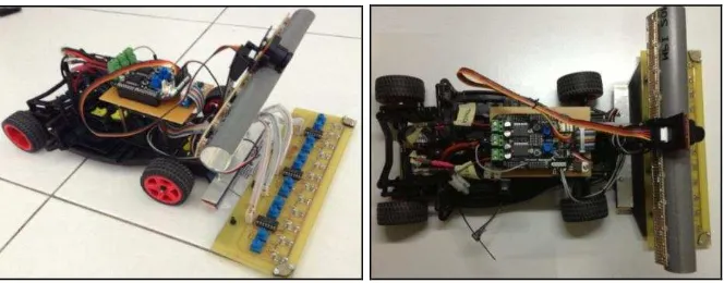
The features of autonomous line following robot are using a 1/18 scale model of the car chassis, two 7.2V DC motors for two rear wheels, the control system which is using Freescale Development Board, a servo motor as the steering of the car and a line scan camera.
[image:17.612.178.510.483.613.2]This is an improvement project where the project designed before as shown in Figure 1.1.1. The pictures shows that it have two input parts which are the IR array to detect the position of the line and a line scan camera that used to know condition of the racetrack in front of the car whether it is a straight line or there is a curve.
2.7 Problem Statements
This is an improvement project where there are a few problems indentified after the first implementation. The problems are:
i. The speed of DC motor is not changeable accordingly to the condition of racetrack.
ii. The speed of the DC motor are not stable because it is totally depends on the capacity of the battery.
The disadvantage with DC motor is it does not have system to control its speed, the first is the speed of the car must be decided based on the maximum speed that the car can pass through the minimum radius of the curve of the racetrack otherwise, the car will derail out from the track. The second problem is, even though the car have been set with a maximum speed for minimum curvature, the same speed also used for the car at the straight line which cause the speed will be slower since it can move faster in straight line.
4
2.8 Project Objectives
The objectives of the project are to overcome the problems of the line following robot. The objectives are as follows:
i. To design control system for speed of the wheels according the condition of the racetrack.
ii. To use the suitable sensor to detect and control the speed of the car wheels.
The first proposed objective is to make the speed is controllable automatically based on the condition of the racetrack. There are two speed suggested which are speed on the straight line and speed on the curve of the racetrack.
The second objective is to make the speed of the robot as a closed loop system is by applying a suitable sensor and the sensitivity of the sensor must meet the maximum speed of the DC Motor used. This is to make sure that the car is always in a constant speed as desired.
2.9 Scope of Work
2.10 Project Methodology
There are a few methods to achieve the project objectives. The first method is by designing the algorithm for line scan camera to detect the position of the line. This algorithm design so that the line position data will updated to servo and rear DC motors algorithm to control the movement of the robot.
The PID control system is applied for the servo motor so that the movement of the robot is more stable to improve the speed especially when turning on the curve.
The second part is by using speed sensor as a feedback path to the control system so that the actual output is identified. This closed loop system will allow the control system to correct the difference between the desired and actual values or also called as the error.
The last part is by using related algorithm to make the speed is changeable based on the condition of racetrack. For this design there are two types of speed which are on curve and on straight line speeds.
2.11 Report Structure
Chapter one will explain about the background and characteristics of the project. The objectives of project improvement based on the problem faced in the first implementation. Other than that is the explanation of scope of the project, a brief explanation about the project methodology and also the report structure.
In Chapter two, all related literature reviews are included. All related references that related to this project explained and discussed to know the concepts that can be applied for the project implementation.
6
All result and analysis will be discussed in Chapter four. It is including on the problem faced when implementing the project and the solution methods to get the desired result.
CHAPTER II
LITERATURE REVIEW
8
3.1 Image processing Using Line Scan Camera (Thresholding)
According to the first reference of D. A. Lehotsky [1], for the grayscale camera, it contains 8-bits data which is the value of one bit can be 0 until 255. The 0 indicates black colour, 255 is white value and between them is gray colour with difference brightness. In that reference, it tries to represent a ball shape product that sense through a line scan camera as in digital values. The idea is applied in product inspection which is to identify whether the product is a defect or acceptable.
[image:23.612.156.540.420.554.2]After getting the data from the camera which the data is in range 0 to 255, there is a threshold called Static Gray Scale Tresholding where it is divided into two types of threshold which are upper and lower thresholds. It means that there are only two data needed to inspect the product and the rest are not taken into account. It can be illustrated in Figure 2.1.1. However for this project, it will only have one threshold which is lower threshold since it is enough to differentiate between two colours (black and white).
3.2 Speed Sensor Using Encoder
The reference of Marinus Maris [2] explained the type of speed sensor used in their autonomous robot. The speed sensor called as Encoder where it use IR sensor to detect black and white strips that sticks on the wheel. The signal is differentiated with the amount of light that receive by the sensor where the amount of light reflected from black colour are less than the white colour of the strips. The output signal from IR sensor is analogue type then connected to the comparator circuit as ADC (Analogue to Digital Converter) to produce digital output as shown in Figure 2.2.1.
[image:24.612.187.502.442.618.2]The output of the ADC circuit then connected to the microcontroller unit to process the data to control the speed of the DC motors. For this project, this concept will be used for identifying the current speed of the robot so that it can be controlled if the speed is not same as set by the user. The speed is in terms of counter number in a fixed period where this number will set by the user first then the measured counter will be compared with the set counter to indentify the error for control system.
![Figure 2.1.1 Example of Static Thresholding [1]](https://thumb-ap.123doks.com/thumbv2/123dok/527571.60817/23.612.156.540.420.554/figure-example-of-static-thresholding.webp)
![Figure 2.2.1 Encoder Circuit Diagram [2]](https://thumb-ap.123doks.com/thumbv2/123dok/527571.60817/24.612.187.502.442.618/figure-encoder-circuit-diagram.webp)
