Abstract—This paper presents the modeling and simulation of wind turbine driven by doubly-fed induction machine as a part of distributed generation which feeds ac power to the distribution network. A stator flux oriented vector control is used for the variable speed doubly-fed induction machine operation. By controlling the generator excitation current the amplitude of the stator EMF is adjusted equal to the amplitude of the grid voltage. To set the generator frequency equal to the grid one, the turbine pitch angle controller accelerates the turbine/generator until it reaches the synchronous speed. The system is modeled and simulated in the Matlab Simulink environment in such a way that it can be suited for modeling of all types of induction generator configurations. The model makes use of rotor reference frame using dynamic vector approach for machine model. The system is also simulated when a fault occurs in 25 kV grid of distribution system. The results of a single line to ground fault and a symmetrical three-phase ground fault is analyzed. The results show that the wind energy conversion system can normally operate in fault conditions.
Index Terms—Distributed Generation, Doubly-Fed Induction Machine, Wind Energy Conversion Systems, Matlab.
I. INTRODUCTION
istributed Generation (DG) is typically defined as small generators, usually less than 30-MW, that are connected to transmission or distribution systems. The emerging new techniques such as small combustion turbines, fuel cells, wind energy, solar energy, and superconducting magnetic energy storage (SMES) make DGs more and more affordable and popular. The government of Indonesia has targeted that DGs from renewable energy resources for up to 5% of all new generation going online by the year 2025 [1]. The target has been emerged because the conventional energy sources are limited and have pollution to the environment.
Wind energy is the fastest growing and most promising renewable energy source among them due to economically viable [2-4]. Many applications of wind power can be found in a wide power range from a few kilowatts to several megawatts in small scale off-grid standalone systems or large scale grid-connected wind farms. Recently Enercon constructed a wind turbine of 4.5 MW with rotor diameter of 112.8 meters. Due to lack of control on active and reactive power, this type of distributed power generation causes problems in the electrical connected system. So this requires accurate modeling, control and selection of appropriate wind energy conversion system.
During last two decades, the high penetration of wind turbines in the power system has been closely
related to the advancement of the wind turbine technology and the way of how to control. Doubly-fed induction machines are receiving increasing attention for wind energy conversion system during such situation. because the main advantage of such machines is that, if the rotor current is governed applying field orientation control-carried out using commercial double sided PWM inverters, decoupled control of stator side active and reactive power results and the power processed by the power converter is only a small fraction of the total system power. So, doubly-fed induction machine with vector control is very attractive to the high performance variable speed drive and generating applications [5-6]. With increasing penetration of wind-derived power in interconnected power systems, it has become necessary to model the complete wind energy systems in order to study their impact and also to study wind power plant control. In this paper, an attempt to develop a dynamic model of induction machine which can be simulated as both motoring and generating mode when testing control strategies. Through the model developed in this paper can be used for simulating all types of induction generator configurations. The choice of synchronous rotating reference frame makes it particularly favorable for the simulation of doubly-fed configuration in transient conditions. The induction machine is modeled in vectorized form in the synchronous reference frame. The speed is adjusted by the turbine pitch control to maximize the power generated at a given wind speed.
Modeling and Simulation of Wind Energy Conversion System
in Distributed Generation Units
RAMADONI SYAHPUTRA1,2,MOCHAMAD ASHARI1,IMAM ROBANDI1
1Department of Electrical Engineering
Faculty of Industrial Technology, Institut Teknologi Sepuluh Nopember, Surabaya, Indonesia
2
Department of Electrical Engineering
Faculty of Engineering, Universitas Muhammadiyah Yogyakarta, Yogyakarta, 55183, Indonesia Email: ramadoni11@ mhs.ee.its.ac.id, [email protected], [email protected]
A complete simulation model is developed for such machine under variable speed operation using MATLAB Simulink environment.
II. FUNDAMENTAL THEORY
A. Distributed Generation
Distributed generations (DGs) sometimes provide the most economical solution to load growth. Low voltages or overloads that are created by load growth may only exist on a circuit for a small number of hours per year. There are many locations within the troubled circuit, or even in neighboring circuits, where a DG may be located to provide control needed to eliminate the low voltage or overload. We assume that it has already been justified that a DG provides the lowest cost solution to a circuit problem and is to be installed to provide the needed control. Placing DGs further out on the circuit can lead to improvements in losses, reliability, or both.
B. Wind Energy Conversion System
There were several attempts to build large scale wind powered system to generate electrical energy. The first production of electrical energy with wind is the wind velocity in m/sec. The power coefficient Cp gives the fraction of the kinetic energy that is converted into mechanical energy by the wind turbine. It is a function of the tip speed ratio λ and depends on the blade pitch angle for pitch-controlled turbines. The tip speed ratio may be defined as the ratio of turbine blade linear speed and the wind speed
(2) Substituting (2) in (1), we have:
(3)
The output torque of the wind turbine Tturbine is calculated by the following equation (4):
(4)
where R is the radius of the wind turbine rotor (m) There is a value of the tip speed ratio at which the power coefficient is maximum. Variable speed turbines can be made to capture this maximum energy in the wind by operating them at a blade speed that variable speed generation, an induction generator is considered attractive due to its flexible rotor speed characteristic in contrast to the constant speed characteristic of synchronous generator.
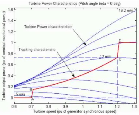
Fig.1. Wind turbine characteristics.
In this study, the rotor is running at subsynchronous speed for wind speeds lower than 10 m/s and it is running at a super-synchronous speed for higher wind speeds. The turbine mechanical power as function of turbine speed is displayed in for wind speeds ranging from 5 m/s to 16.2 m/s.
C. Doubly-Fed Induction Machine
is coupled to the power system through a connecting transformer. Due to different operating speeds of the wind turbine rotor and generator, a gearbox is used to match these speeds. The generator slip slightly varies with the amount of generated power and is therefore not entirely constant.
General concept of the doubly-fed induction machine is shown in Fig.2. [7]. The mechanical power generated by the wind turbine is transformed into electrical power by an induction generator and is fed into the main grid through the stator and the rotor windings. The rotor winding is connected to the main grid by self-commutated AC/DC converters allowing controlling the slip ring voltage of the induction machine in magnitude and phase angle. In contrast to a conventional, singly-fed induction generator, the electrical power of a doubly-fed induction machine is independent from the speed. Therefore, it is possible to realize a variable speed wind generator allowing adjusting the mechanical speed to the wind speed and hence operating the turbine at the aerodynamically optimal point for a certain wind speed range.
Fig.2. Typical of doubly-fed induction machine [7].
Half of the world’s leading wind turbine manufacturers use the doubly fed induction generator systems [10]. This is due to the fact that the power electronic converter only has to handle a fraction (20%
– 30%) of the total power, i.e., the slip power. This means that if the speed is in the range ±30% around the synchronous speed, the converter has a rating of 30% of the rated turbine power, reducing the losses in the power electronic converter, compared to a system where the converter has to handle the total power. In addition, the cost of the converter becomes lower. The doubly fed induction machine has been used in wind turbines for a long time. In the past, the ACAC converter connected to the rotor consisted of a rectifier and inverter based on thyristor bridges. Nowadays, AC-AC converters are equipped with bidirectional IGBT's, connecting the rotor of the variable speed doubly fed induction generator to the electrical grid.
III. MODELING THE SYSTEM
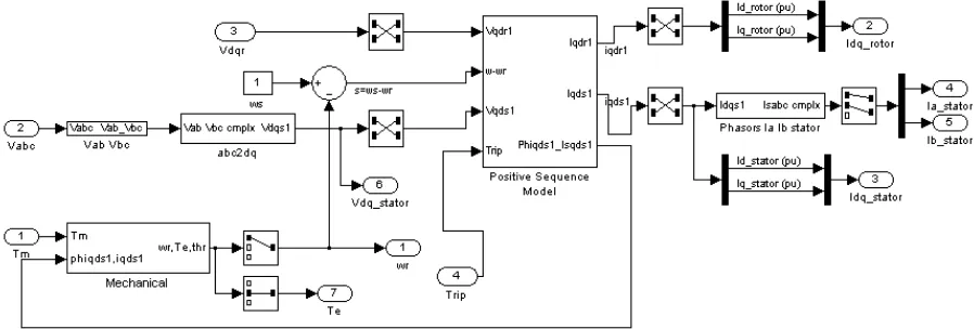
In this research, physical model of the wind energy conversion system with doubly-fed induction machine connected to grid of distribution system is implemented in Matlab Simulink software. The system models constituting elements of the system separately and also considers interrelationship among different elements within the system, where type and structure of the model is normally dictated by the particular requirements of the analysis, e.g. steady-state, fault studies, etc. Indeed, due to the importance of more realistic production of the behavior of doubly-fed induction machine, it is intended to adopt physical model rather than functional model in order to accurately assess performance of doubly-fed induction machine in the event of fault particularly in determining whether or not the generator will trip following a fault. Fig.3 shows induction machine stator currents and grid-side converter currents, while Fig.4 shows the wind turbine model. In order to simulate the overall of the system, distribution power system with distributed generation including wind energy conversion system is also illustrated in Fig.5.
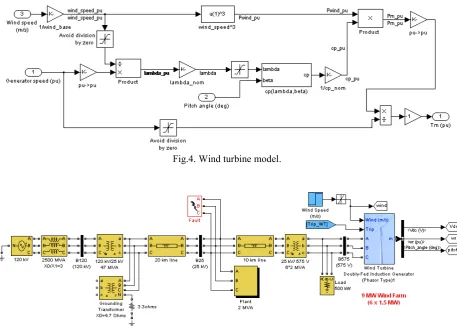
Fig.4. Wind turbine model.
Fig.5. Wind energy connected to a distribution system.
IV. EXPERIMENTAL RESULTS
The presented model is simulated using Matlab Simulink software to investigate the doubly-fed induction machine operation during starting, normal running, and fault conditions. The example described in this section illustrates the steady-state and dynamic performance of a 9 MW wind farm connected to a distribution system. The wind farm consists of six 1.5 MW wind turbines connected to a 25 kV distribution system exporting power to a 120 kV grid through a 30 km 25 kV feeder. A 2300V, 2 MVA plant consisting of a motor load (1.68 MW induction motor at 0.93 PF) and of a 200 kW resistive load is connected on the same feeder at bus B25. A 500 kW load is also connected on the 575 V bus of the wind farm. The diagram of this system in Matlab Simulink model is illustrated in Fig.5.
Both the wind turbine and the motor load have a protection system monitoring voltage, current and machine speed. The DC link voltage of the DFIG is also monitored. Wind turbines use a doubly-fed induction machine consisting of a wound rotor induction generator and an AC/DC/AC IGBT-based PWM converter. The stator winding is connected directly to the 60 Hz grid while the rotor is fed at
variable frequency through the AC/DC/AC converter. The doubly-fed induction machine technology allows extracting maximum energy from the wind for low wind speeds by optimizing the turbine speed, while minimizing mechanical stresses on the turbine during gusts of wind. The optimum turbine speed producing maximum mechanical energy for a given wind speed is proportional to the wind speed. Another advantage of the doubly-fed induction machine technology is the ability for power electronic converters to generate or Turbine Data Menu and the Turbine Power Characteristics absorb reactive power, thus eliminating the need for installing capacitor banks as in the case of squirrel-cage induction generators. The terminal voltage will be controlled to a value imposed by the reference voltage (Vref = 1 pu) and the voltage droop
(Xs = 0.02 pu).
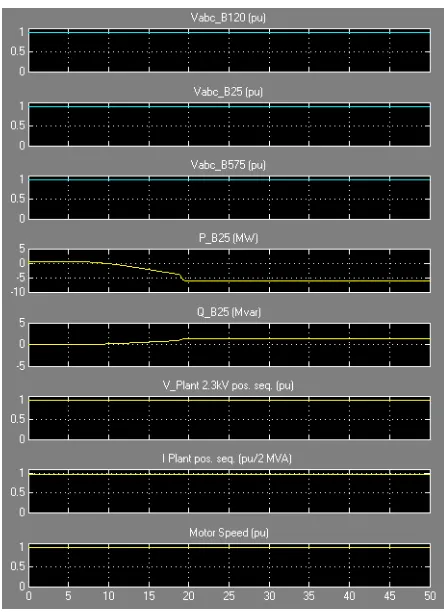
A. Simulation of Turbine Response to a Change in Wind Speed
starts increasing smoothly (together with the turbine speed) to reach its rated value of 9 MW in approximately 15s. Over that time frame the turbine speed increases from 0.8 pu to 1.21 pu.
Fig.6. Waveforms for a gust of wind in voltage regulation mode.
Initially, the pitch angle of the turbine blades is zero degree and the turbine operating point follows the red curve of the turbine power characteristics up to point D. Then the pitch angle is increased from 0 deg to 0.76 deg to limit the mechanical power.
The voltage and the generated reactive power is also observed. The reactive power is controlled to maintain a 1 pu voltage. At nominal power, the wind turbine absorbs 0.68 MVar (generated Q=-0.68 MVar) to control voltage at 1pu. If the mode of operation is changed to Varregulation with the Generated reactive power Qref set to zero, the voltage increases to 1.021 pu when the wind turbine generates its nominal power at unity power factor.
Fig.7. Waveforms for a gust of wind in Var regulation mode.
B. Simulation of Single Line to Ground Fault on the 25 kV System
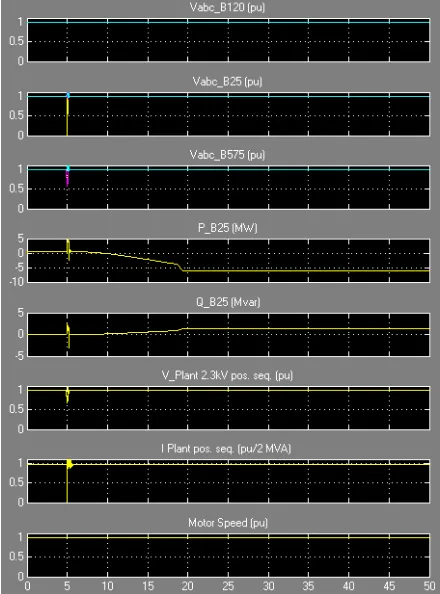
Fig.8. Waveforms for a single line to ground fault on 25 kV system in voltage regulation mode.
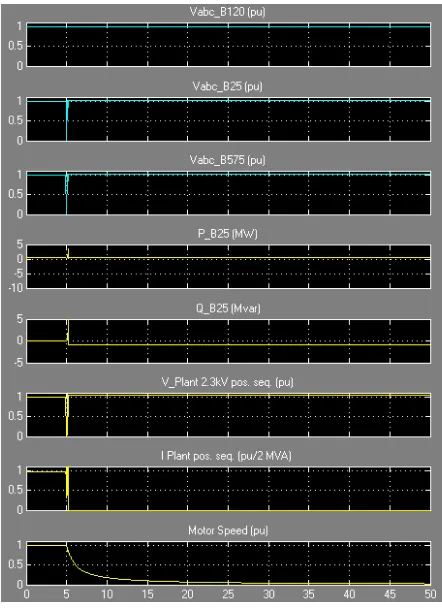
Fig.9. Waveforms for a single line to ground fault on 25 kV system in Var regulation mode.
As can be seen in Fig.9 that the plant does not trip anymore. This is because the voltage support provided by the 5 Mvar reactive power generated by the wind turbines during the voltage sag keeps the plant voltage above the 0.9 pu protection threshold. The plant voltage during the voltage sag is now 0.93 pu.
C. Simulation of Symmetrical Three Phase Fault on the 25 kV System
Finally, now observe the impact of a single phase-to-ground fault occurring on the 25 kV line. At t=5 s a 9 cycle (0.15 s) phase-to-ground fault is applied on phase A at B25 bus. When the wind turbine is in Voltage regulation mode, the positive sequence voltage at wind turbine terminals (V1_B575) drops to 0.8 pu during the fault, which is above the undervoltage protection threshold (0.75 pu for a t>0.1 s). The wind farm therefore stays in service, as shown in Fig.10. However, if the Var regulation mode is used with Qref=0, the voltage drops under 0.7 pu and the undervoltage protection trips the wind farm. We can now observe that the turbine speed increases. At t=40 s the pitch angle starts to increase to limit the speed, as shown in Fig.11.
Fig.11. Waveforms for a symmetrical three phase fault on 25 kV system in Var regulation mode.
V. CONCLUSIONS
This paper has described the modeling and simulation of wind turbine driven by doubly-fed induction machine as a part of distributed generation which feeds ac power to the distribution network. A stator flux oriented vector control is used for the variable speed doubly-fed induction machine operation. By controlling the generator excitation current the amplitude of the stator EMF is adjusted equal to the amplitude of the grid voltage. To set the generator frequency equal to the grid one, the turbine pitch angle controller accelerates the turbine/generator until it reaches the synchronous speed. The system is simulated when a fault occurs in 25 kV grid of distribution system. The results of a single line to ground fault and a symmetrical three phase ground fault show that the wind energy conversion system can normally operate in fault conditions. This condition can be achieved by using the reliable protection system.
VI. REFERENCES
[1] Kusdiana, D., ―Kondisi Riil Kebutuhan Energi di Indonesia dan Sumber-Sumber Energi Alternatif Terbarukan‖, Presented at the Seminar of Renewable Energy, Direktorat Jenderal Listrik dan Pemanfaatan Energi Departemen Energi dan Sumber
Daya Mineral, Bogor, 3 Dec. 2008.
[2] A. Tapia, G. Tapia, J. X. Ostolaza, and J. R. Saenz, ―Modeling and control of a wind turbine driven doubly fed induction
generator,‖ IEEE Transactions on Energy Conversion, Vol.18, pp. 194-204, 2003.
[3] Y. Lei, A.Mullane, G.Lightbody, and R.Yacamini, ―Modeling of the Wind Turbine With a Doubly Fed Induction Generator
for Grid Integration Studies,‖ IEEE Transactions on Energy
Conversion, Vol. 21(1), pp.257-264, 2006.
[4] H.Li and Z.Chen, ―Overview of generator topologies for wind
turbines,‖ IET Proc. Renewable Power Generation, vol. 2, no. 2, pp. 123–138, Jun.2008.
[5] L. Mihet-Popa and F.Blaabrierg, ―Wind Turbine Generator Modeling and Simulation Where Rotational Speed is the
Controlled Variable‖, IEEE Transactions on Industry
Applications, Vol. 40, No.1, Jan./Feb. 2004.
[6] B.H.Chowary and S.Chellapilla, ―Doubly-fed induction
generator for variable speed wind power generation‖
Transactions on Electric Power System Research, Vol.76,pp.
786-800, Jan . 2006.
[7] M.A. Poller, ―Doubly-Fed Induction Machine Models for Stability Assessment of Wind Farms”, Power Tech Conference
Proceedings of 2003 IEEE Bologna, Vol.3, 6 pp. 23-26 June
2003.
[8] B.C. Babu and K.B. Mohanty, ―Doubly-Fed Induction Generator for Variable Speed Wind Energy Conversion Systems - Modeling & Simulation‖, International Journal of
Computer and Electrical Engineering, Vol. 2, No. 1, pp.
1793-8163, February, 2010.
[9] T. T. Chuong, ―Voltage Stability Investigation of Grid
Connected Wind Farm‖, World Academy of Science,
Engineering and Technology, Vol. 42, pp. 532-536, 2008.
[10] J.G. Slootweg, S. W. H. Haan, H. Polinder, and W.L. Kling.
―General Model for Representing Variable Speed Wind
Turbines in Power System Dynamics Simulations‖. IEEE
Trans. on Power Systems, Vol. 18, No. 1, February, 2003.