Doubly-Salient Wound-Field Machine
Liwei Shi1,2*, Bo Zhou1
1
Shandong University of Technology, Zibo, Shandong, 255091, China
2 Aero-Power Science-Technology Center/ Nanjing University of Aeronautics and Astronautics, Nanjing
210016, China
*Corresponding author, e-mail: [email protected]
Abstract
Doubly Salient Wound-Field Machine (DSWFM) can be employed on aeronautics starter-generator because it has good performance on both power generation and starting. To improve the system reliability, a three-phase four bridge legs converter which has fault tolerant capability is proposed to solve one phase open-circuit fault problem of the DSWFM. And the advantage of the proposed converter to the full-bridge converter fault-tolerant mode is analyzed. With the study of DSWFM theory and torque equation, a constant torque fault-tolerant strategy is proposed to keep the performance and reduce the torque ripple. The drive system after fault identification can be reconstructed by the proposed method, and the machine performance can recover quickly. Simulations confirm the feasibility of the proposed fault tolerant system.
Keywords: Doubly Salient Electro-magnet Machine (DSWFM); Fault Tolerant; Converter; Phase Open
1. Introduction
Doubly Salient Wound-Field Machine (DSWFM) is a new type of brushless DC machine that comes from DSPM by using field winding instead of permanent magnet excitation in 1990s[1]-[3]. Its armature windings and excitation windings are both mounted on the SRM-structured stator, and it is with similar salient rotor structure to SRM rotor. DSWFM has such advantages as simple structure, low cost, high reliability and good fault-tolerance [4]-[6]. Thus it has good application prospects in many fields including wind power generation, aeronautics, astronautics, automobiles and ships, especially in engine starter-generator.
The reliability of the DSWFM system is extremely important in starter-generator, fuel transmission and braking application. To improve the reliability of the whole system, several papers have studied about the development for fault tolerant inverter system, because the inverter is the weakest link of the motor drive system[7]-[12]. But these papers just focus on traditional machine such as PM machine and induction machine. As DSWFM machine is deferent from those traditional machine, it is necessary to develop a new fault-tolerant topology and a new control strategy to improve the reliability of the DSWFM system.
Based on the analysis of special characteristics of DSWFM system, this paper proposes a simple fault detection and isolation scheme when a open-switch fault occur in the full-bridge inverter of DSWFM. After fault identification, faulty leg will be isolated by control signal. The system after faults is operated with fault tolerant mode. The theoretical operating principle of DSWFM and the proposed fault detection identification algorithm are explained in detail. Simulation results verify the proposed fault tolerant scheme.
2.Principle and Analysis
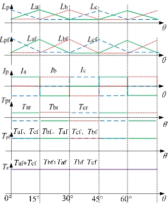
The typical structure of DSWFM is shown in Figure 1: It has 12 stator poles, 8 rotor poles and four excitation winding coils. Each stator has a concenrated phase windings independently, and the phase winding coils with the same electric angle is linked in series, which build Phase A, B and C.
Figure 1 Cross section of DSWFM
Figure 2. Full-bridge converter topology on DSWFM
Without the consideration of such factors as side effect, magnetic reluctance of core, and so on, the phase self-inductance
L
p and mutual-inductance between phase and excitingwinding
L
pf of each phase makes the distribution in Figure 3. And its values have relationshipwith rotor angle but not with stator current. While the phase current
i
p is shown in Figure 3.Figure 3. Output torque of a normal DSWFM
One phase torque equation of DSWFM is shown in [14]
p pf 2
p p p f
pr pf
d d
1
2 d d
L L
T i i i
T T
(1)
Where
T
p is the output torque of phase p,T
pr is the phase magnetic resistance torque, pfT
is the phase excitation torque, if is the excitation current,p
L
is the phase self-inductance,Lpf is the mutual-inductance, is the rotor position angle. For a 12/8 poles DSWFM, the output torque of a normal DSWFM can be drawn in Figure 1. Generally,
T
pr is much smaller thanT
pfin their absolute values.
pr
T
produced by two phase windings can cancel out each other [14]. When switch T1,T4 are turned on, phase A and C works, in other words, the machine woks in [0°, 15°] sector in Figure1, for example:
a c
2 a af
a a a f
2 c cf
c c c f
1 d d
2 d d
1 d d
2 d d
L L
T i i i
L L
T i i i
(2)
Because of d a d c
d d
L L
,2 a 2 c
a c
1
d
1
d
2
d
2
d
L
L
i
i
, Letaf cf L
d
d
d
d
L
L
k
(3) So the total output torque of the machine is :af cf e a c a f c f
d
d
d
d
L
L
T
T
T
i i
i i
2
T
pf
2
ii k
f L (4)3. Fault Tolerant Mechanism of DSWFM 3.1 Fault Detection and Identification
Because of the T1, T2 open fault has the same performace with phase A open winding, both of the phase windings and inverter failure can be classified as phase open fault. Moisture, overheat, erosion environment and the impact of external forces can cause damage to the DSWFM winding, these fault can also be divided into open-circuit fault and short-circuit fault. The inverter is the weakest link of the system, it can be suffered by the open-circuit fault and short-circuit fault. The open-circuit fault occurs due to over-current or control device deterioration, the short-circuit fault also often happens because of over-voltage.
The phase short faults are often protected by fuse. So this paper mainly introduced phase open faults.
For example, in Figure 2, when phase C is open, it should be removed immedietly. Then phase A and B can not form a circiut loop with phase C. As shown in Figure 3, in [15°, 30°], the output torque of the motor is normal. But the motor output torque is 0 in [0°, 15°]. and [30°, 45°], as shown in Figure 3. So it is necessary to reconstruct the system converter to achieve fault-tolerant operation.
Phase open fault detection can be realized by three-phase current sensor. Because the three-phase winding conducts pairwise, when the rotor is in [0°, 15°], phase A and C current is normal, while in the other period this two phases current are greater than 1.5 times or less than 0.2 times the predetermined current, then short-circuit or open-circuit fault of phase B can be drawn from this phenomenon. In this way, we can determine the short-circuit or open-circuit fault of the other phases.
0.00 0.50 1.00 1.50 2.00 2.50 3.00 3.50 4.00 Time [ms]
-25.00 -12.50 0.00 12.50 25.00
Y1 [A]
LA.I
LC.
LB.I
Phase winding with short-circuit or open-circuit fault should be disconnected by the fuse and control system, and the machine should be operated on fault-tolerant mode.
3.2 Full-bridge Converter Fault-tolerant Mode
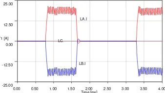
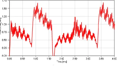
For the same example, when phase C is on open-circuit fault, it will not conduct in [0°, 15°]. We can turn on T1 and T6 to power phase A and phase B to drive the motor in fault-tolerant mode in [0°, 15°]. In [15°, 45°], we can turn on T3 and T4 to supply power to phase B and phase A. Three phase current of DSWFM on full-bridge converter fault-tolerant mode is shown in Figure 4. And DSWFM output torque on phase C open full-bridge converter fault-tolerant mode is shown in Figure 5.
Figure 4. Three phase current on phase C open full-bridge converter fault-tolerant mode
Figure 5. DSWFM output torque on phase C open full-bridge converter fault-tolerant mode
However, this fault-tolerant mode has three shortcomings:
First of all, phase B and A energized at the same time but only one phase can generate torque, the other phase plays the role of a loop winding, which reduces the efficiency of the motor; At the same time, phase B and A work at the full time and its large current may cause a system failure; In addition, the phase B and A pass the same circuit, their excitation torque is equal, but its reluctance torque is in the opposite direction, it will generate a lot of torque ripple.
3.3 Three-phase Four Bridge Legs Converter Fault-tolerant Mode
Owing to the connection of two-phase, of DSWFM machine with full-bridge converter has low performance in fault tolerant operation. To meet the requirement of the electric independence, a fault tolerant motor drive should detect and isolate the fault phase without any effect on other healthy phases. The machine can be operated with other healthy phases working during loss of one phase.
A high reliability, three-phase four bridge legs converter which has fault tolerant capability is proposed in Figure 6 to solve one phase open-circuit fault problem of the DSWFM. It only applies two more switches than the traditional full-bridge converter, and it can avoid the above shortcomings of the full bridge converter fault-tolerant mode.
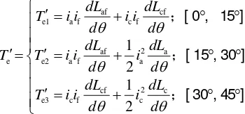
For the same example, when phase C is on open-circuit fault, we can turn on T1 and T8 to power phase A to drive the motor in fault-tolerant mode in [0°, 15°], as shown in Figure 7, the total output torque is the sum of phase A magnetic resistance torque Tar and phase A excitation torque Taf. As self-inductance of phase A and mutual-inductance between phase A and exciting winding F is in the increase, Tar and Taf both large than 0.
In [15°, 30°], the output torque of the motor is normal.
In [30°, 45°], we can turn on T7 and T6 to power phase B to drive the motor in fault-tolerant mode. The total output torque is the sum of phase B magnetic resistance torque
T
br and phaseB excitation torque
T
bf. As self-inductance of phase B and mutual-inductance between phase Band exciting winding
L
bf is in the decrease,af
T
>0 andar
T
<0.Table 1 .Comparison between Full-bridge and Three-phase Four Bridge Legs Converter Fault-tolerant Mode
[0°, 15°] [15°, 30°] [30°, 45°]
Normal working switch T1,T2 T3,T4 T5,T6
Normal working winding A,-C B,-A C,-B
Full-bridge converter fault-tolerant mode working switch T1,T6 T3,T4 T1,T6 Full-bridge converter fault-tolerant mode working winding A,-B B,-A A,-B Four bridge legs converter fault-tolerant mode working switch T1,T8 T3,T4 T7,T6 Four bridge legs converter fault-tolerant mode working winding A B,-A -B
Figure 6 Three-phase four bridge legs fault-tolerant converter
Figure 7 Three-phase four bridge legs converter fault-tolerant mode
4. Constant Torque Fault-tolerant Strategy
Assuming the normal output torque of the motor:
e
2
pf2
f LT
T
ii k
With the proposed four bridge legs converter fault-tolerant mode, if the current of phase A and B is equal to the normal state when phase C is on open-circuit fault, then the output torque of the motor
T
e
:af cf
e1 a f c f
2
af a
e e2 a f a
2
cf c
e3 c f c
1 2 1 2
dL dL
T i i i i
d d
dL dL
T T i i i
d d
dL dL
T i i i
d d
;[ 0 , 15 ]
;[ 15 , 30 ]
;[ 30 , 45 ]
(5)
We can keep the output torque in fault-tolerant state of the same by changing three-phase current.
Assuming the current of phase A in [15°, 30°] is
i
a2, and the current of phase C in [30°,45°] is
i
c3, then the output torque:e
T
:af cf
e1 a f c f
2
af a
e e2 a2 f a2
2
cf c
e3 c3 f c3
1 2 1 2
dL dL
T i i i i
d d
dL dL
T T i i i
d d
dL dL
T i i i
d d
;[ 0 , 15 ]
;[ 15 , 30 ]
;[ 30 , 45 ]
(6)
That is to say, we can keep the three-phase armature current of the motor be consistent with the equation (6) in order to ensure the output torque constant.
5. Simulation and Verification
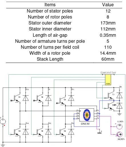
A prototype machine of DSWFM has been designed. Table 2 gives key parameters of the machine.
Table 2. Protatype machine parameters
Items Value
Number of stator poles 12 Number of rotor poles 8
Stator outer diameter 173mm Stator inner diameter 112mm Length of air-gap 0.35mm Number of armature turns per pole 5
Number of turns per field coil 110 Width of a rotor pole 14.4mm
Stack Length 60mm
0 D15 Q4 Q1 Q3 Q6 D1 D11 D12 D13 D14 Q2 42V E1 + SM_ROT1 +V_ROT1 EQUBL Q5 D8 T7 D7 T1 T2 T3 T4 T5 T6 T7 T8 IGBT1
Figure 8 Simulation Model of DSWFM Phase Open Fault Tolerant
In equation (6), let
e1 e2 e3
0
0
0
b
a
c
a
i
i
i
i
; [ 30 , 45 ]
; [ 0 , 45 ]
; [ 0 , 15 ]
; [ 15 , 30 ] 1. 6 ; [ 30 , 45 ]
(7)
In order to assess the aforementioned normal and faulty-tolerant performance of the DSWFM machine, the cosimulation technique is adopted in which the magnetic circuit and the electric circuit are coupled in the time domain. The modeling tools for the cosimulation are composed of three packages, the 2D FEA model, three-phase four bridge legs fault-tolerant converter model and controller model. The magnetic solver performs with coupled field-circuit is established and shown in Figure 8.
At each cosimulation time step, both the magnetic and circuit solvers exchange the calculated data, and the results produced by one solver will be exported to another solver in the next step. Consequently, the system performances can be accurately simulated.
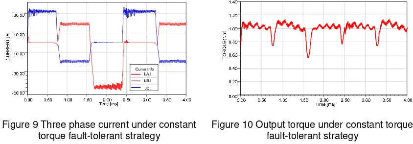
Three phase current of DSWFM on under constant torque fault-tolerant strategy is shown in Figure 9. And DSWFM output torque is shown in Figure 10.
Figure 9 Three phase current under constant torque fault-tolerant strategy
Figure 10 Output torque under constant torque fault-tolerant strategy
The state in [0ms, 0.8ms] is corresponding to motor mechanical angle in [0°, 15°] in equation (7), the current of phase A is 1.6 times of the rated current. The state in [0.8ms, 1.6ms] is corresponding to motor mechanical angle in [15°, 30°], its phase current is equal to the normal mode. The state in [1.6ms, 2.4] is corresponding to motor mechanical angle in [30°, 45°]. At this time, the current of phase C is -2.4 times of the rated current. The output torque under constant torque fault-tolerant strategy is almost equal to the normal working time.
6. Conclusion
The DSWFM system can be reconstructed after fault identification by the proposed four bridge legs converter tolerant mode, and the machine performance can recover quickly.
The proposed four bridge legs converter tolerant mode has no loop winding, which increases the efficiency of the motor. In addition, the four bridge legs converter tolerant mode windings current of the two phase can be controlled individually to achieve a smooth output torque.
With the constant torque fault-tolerant strategy, the proposed system can keep the normal performance with phase open fault and reduce the torque ripple. Simulations confirm the feasibility of the proposed fault tolerant system.
Acknowledgment
This work was supported by the national Natural Science Foundation of China under Award 51177069, National Basic Research Program of China (973 Program) under Project 2007CB210302, and by the aeronautic science foundation of China under project 2010ZC52034.
References
[1] Zheng, Qin, Shin, Kang G. Fault-tolerant real-time communication in distributed computing systems.
IEEE Transactions on Parallel and Distributed Systems. 2008; 9(5): 470-480.
[2] Zhao W, Cheng M, Zhu X, and et al. Analysis of fault-tolerant performance of a doubly salient permanent-magnet motor drive using transient cosimulation method. IEEE Transactions on Industrial
Electronics. 2008; 55(4): 1739-1748.
[3] A. M. El-Refaie. Fault-Tolerant Permanent Magnet Machines: A Review. IET Electric Power
Applications. 2011; 5(1): 59-74
[4] Qun-Tao A, Li-Zhi S, Ke Z, Li S. Switching Function Model-Based Fast-Diagnostic Method of Open-Switch Faults in Inverters Without Sensors. IEEE Transactions on Power Electronics. 2011; 26(1): 119-126
[5] Yongxin, Feng, Tao, Yang, Wenguang, Yang, Dongxiang, Jiang. Study of fault diagnosis method for wind turbine with decision classification algorithms and expert system. Telkomnika. 2012; 10(5): 905-91.
[6] Pan, Wang, Fei, Liu, Xiaoming, Zha, Jianhua, Yu, and et al. Research on a new type of energy feedback cascade multilevel inverter system. Telkomnika. 2013; 11(1): 494-502.
[7] Zang L, Zhao Y, Wang W, Wang, Jian, Sun H. Simulation of electromagnetic characters of vehicle
whip antennas based on MoM. Proceedings of the FISITA 2012 World Automotive Congress. 2013;
1: 565-572.
[8] S. Mir, M. S. Islam, T. Sebastian, I. Husain. Fault-Tolerant Switched Reluctance Motor Drive Using Adaptive Fuzzy Logic Controller. IEEE Transactions on Power Electronics. 2004; 19(2): 289-295.
[9] HAO Z, HU Y, HUANG W, YU W, XU S. Six-phase Ten-pole Fault Tolerant Permanent Magnet
Machine and Its Control Strategy. Proceedings of the CSEE. 2010; 30(30): 81-86.
[10] Bouji M, Arkadan AA, Ericsen T. Fuzzy inference system for the characterization of SRM drives under normal and fault conditions [J]. IEEE Transactions on Magnetics. 2001; 37(5): 3745-3748.
[11] Arkadan AA, Du P, Sidani M, and et al. Performance prediction of SRM drive systems under normal and fault operating conditions using GA-based ANN method. IEEE Transactions on Magnetics. 2000; 36(4):1945-1949.
[12] Qin H, Zhao C, Wang H, and et al. Mechanisms of possible failures in doubly salient permanent magnet motor. Journal of Nanjing University of Aeronautics & Astronautics. 2006; 38(3): 292-297.
[13] HU C, ZHOU B, WEI J. On-line Diagnosis of Single Transistor Open-circuit Fault in Full-bridge
Converter of Doubly Salient Electro-magnet Motor. Proceedings of the CSEE. 2009; 29(33): 111-117.
[14] Wei J, Zhou B. Project on single phase open-circuit fault tolerance of doubly salient electro-magnet
motor driven by full-bridge converter. Proceedings of the CSEE. 2008; 28(24): 88-93.
[15] W. Zhao, M. Cheng, W. Hua, and et al. Back-EMF Harmonic Analysis and Fault-Tolerant Control of Flux-Switching Permanent-Magnet Machine with Redundancy. IEEE Transactions on Industrial
Electronics. 2011; 58(5): 1926-1936.
[16] Xueyi, Zhang. Study on controlled rectification constant-voltage permanent-magnet rare earth
generator of hybrid vehicles. 2nd International Conference on Intelligent Computing Technology and