DESIGN AND MODELING OF MULTIPLE TANK
CONTROL FOR FLUID CIRCULATION SYSTEM USING
FUZZY CONTROLLER
GWEE CHIOU CHIN
UNIVERSITI TEKNIKAL MALAYSIA MELAKA
Design and Modeling of Multiple Tank Control for Fluid
Circulation System Using Fuzzy Controller
Thesis submitted in accordance with the partial requirement of the
Universiti Teknikal Malaysia Melaka for the
Bachelor of Manufacturing Engineering (Robotic & Automation) with Honours
By
FAKULTI KEJURUTERAAN PEMBUATAN Karung Berkunci 1200, Ayer Keroh, 75450 Melaka
iii
DECLARATION
I hereby, declared this thesis entitled “Design and Modeling of Multiple Tank
Control for Fluid Circulation System Using Fuzzy controller” is the results of my
own research
except as cited in references.
Signature : ……….
Author’s Name : Gwee Chiou Chin
APPROVAL
This PSM submitted to the senate of UTeM and has been as partial fulfillment of the
requirements for the degree of Bachelor of Manufacturing Engineering (Robotic and
Automation) with Honours. The members of the supervisory committee are as
follow:
………
Main Supervisor
En Muhamad Arfauz Bin Abdul Rahman
Faculty of Manufacturing Engineering
v
ABSTRACT
A tank level control is one of the important systems which are used widely in
industry. This control system keeps developing from time to time to replace the
ordinary system which applies mechanical functions in its control in order to
improve the system reliability. There are many applications in industries that are
utilizing this system such as water dam, water treatment system, industry tank
control and also boiler. In order to develop a successful tank fluid level control
system, full understanding on the function and principle of the system is required. In
this project, Matlab Simulink will be used as a main platform in developing the
simulation of the exact control system for the Lamella Filtration system. The system
that been study in this project is the Lamella Filtration system of Bukit Sebukor
Water Treatment Plant. This study is to upgrade the mechanical water level control
system of the Lamella Filtration system to an automatic system. The automation of
the system can reduce the burden of the technicians on shift and prevent human error
on manual operation. The system will be tested to gain the desired control function.
The end result of this project will be a smooth and low error water level control
ABSTRAK
Pengawalan paras tangki merupakan salah satu sistem penting yang luas digunakan
dalam industri pada masa kini. Sistem ini terus membangun untuk menggantikan
sistem biasa yang mengaplikasikan fungsi mekanik dalam pengawalan untuk
memperbaiki kebolehpercayaan sistem. Terdapat banyak aplikasi dalam industri
yang menggunakan sistem ini seperti empangan air, sistem rawatan air, kawalan
tangki industri dan juga pemanas air. Untuk membangun suatu sistem kawalan paras
air yang berjaya, pemahaman yang menyeluruh terhadap fungsi dan prinsip sistem
tersebut diperlukan. Dalam projek ini, Matlab Simulink akan digunakan sebagai alat
uatama dalam menghasilkan simulasi sistem kawalan yang tepat and betul untuk
Sistem Penapisan Lamella. Sistem yang dikaji dalam projeck ini adalah Sistem
Penapisan Lamella Loji Air Bukit Sebukor Melaka. Kajian ini adalah bertujuan
untuk menaik tarafkan sistem mekanikal kawalan air yang ada pada Sistem
Penapisan Lamella yang sedia ada kepada sistem automasi. Pengautomasian sistem
tersebut dapat mengurangkan beban teknisian yang bertugas dan mengurangkan
kesilapan manusia dalam operasi manual..Sistem tersebut akan diuji untuk mendapat
fungsi kawalan yang diingini. Hasil daripada projek ini merupakan satu sistem
kawalan paras air untuk Sistem Penapisan Lamella yang lancar dan rendah
vii
DEDICATION
I dedicate this PSM thesis to my beloved parents, Gwee Tee san and Yew Be Bee,
my beloved brothers, Gwee Chen Ee and Gwee Chen Shang, and my friends,
ACKNOWLEDGEMENTS
With the helps and blessing from God, I managed to complete this project
successfully. First of all, I would like to thank my parent, for their concern and
support, all over the time. Not forgotten my brothers, who had helped me a lot in
supporting me physically and morally.
I also want to thank Mr. Muhamad Arfauz Bin Abdul Rahman from Fakulti
Kejuruteraan Pembuatan, Universiti Teknikal Malaysia Melaka, for supervising me
all along this project, and provide helps, guides, ideas, and suggestions to accomplish
this project. All the supports and motivation that been given to me are greatly
appreciated.
Also not forgotten, Mr. Salleh and Mr. Asmadi from Bukit Sebukor Water Treatment
Plant, for giving a permission to conduct the case study at the Water Treatment Plant.
With a deep sense of gratitude, I would also like to express my sincere thank to my
colleague, Jannatunnaim and Noorhayati for the help and supports that been shown
by them.
Last but not least, thanks to all my friends who had helped me directly or indirectly
ix
List of Abbreviations, Symbols, Specialized Nomenclature………... .xiv
1. INTRODUCTION ………..1
2.5 Water Level and Flow Control Devices ………16
2.5.1 Level Sensor ………16
2.5.2 Flow Meter ………..17
2.5.3 Water Valve ………18
2.6 Fuzzy Logic Controller ……….21
2.6.1 Structure of a Fuzzy Controller ………..24
2.6.2 Fuzzy Logic Toolbox ……….24
2.7 Fuzzy Controller versus PID Controller ………...25
xi
5. DESIGN SIMULATION ...………...50
5.1 Introduction ...50
5.2 System Development ...50
5.3 Development of SIMULINK Block Diagram ...51
6. RESULTS & DISCUSSION……...……….56
6.1 Introduction ...56
6.2 Results ...56
6.3 Concluding Remarks ... 60
7. CONCLUSION & SUGGESTIONS ...61
7.1 Introduction ...61
7.2 Summary ...61
7.3 Conclusion ...63
7.4 Suggestions & Recommendations ...74
LIST OF FIGURES
2.1 Simplified Description of a Control System 6
2.2 Elevator Response 8
2.3 Open Loop System 9
2.4 Closed Loop System 10
2.5 Direct Control 22
2.6 Feed Forward Control 23
2.7 Fuzzy parameter adaptive control. 23
2.8 Blocks of a Fuzzy Controller 24
2.9 Fuzzy Logic Based Control System 27
3.1 Flow of the Project Design 32
3.2 Flow of the System Design 34
4.1 Bukit Sebukor Water Treatment Plant 42
4.2 PLC Monitoring 46
4.3 Filter Control Panel 46
4.4 Lamella Filtration Tank 47
4.5 Lamella Filtration Tank structure (Architecture Drawing) 48
4.6 Lamella Filtration Tank Structure (Simplified Drawing) 49
5.1 Simulink Library Browser 51
5.2 Empty Simulink Window 52
5.3 Block Diagram for the new system. 52
5.4 Water Tank Block Parameters Window 53
5.5 Penstock Block Parameter Window 54
5.6 Rule Editor Window 54
xiii
LIST OF TABLES
3.1 Gantt chart for PSM 1 40
3.2 Gantt chart for PSM 2 42
LIST OF ABBREVIATIONS, SYMBOLS, SPECIALIZED
NOMENCLATURE
AWWA - American Water Works Association
CPVC - Chlorinated PVC
DP - Differential pressure
GUIs - Graphical user interfaces
I/O - Input/Output
P - Proportional
PD - Proportional plus derivative / Positive displacement
PI - Proportional plus integral
PID - Proportional, integral, and derivative
PSM - Projek Sarjana Muda
PTFE - Polytetrafluoroethylene
PV - Photovoltaic
PVC - Polymers, polyvinyl chloride
UV - Ultraviolet
1
level control, and liquid flow control and circulation system.
In this project, the Lamella Filtration system of Bukit Sebukor Water Treatment
Plant is studied. The objective of this project was to upgrade the mechanical water
level control system of the Lamella Filtration system to an automatic system. The
automation of the Lamella Filtration system can help reducing the burden of the
technicians on shift and prevent human error on manual operation.
Previous study on fluid level control using SIMULINK was carried out by previous
student. [15] In his study, the design and modeling tank control for fluid circulation
system using SIMULINK had been designed. Unfortunately, the system is not
suitable to be applied at the current Lamella Filtration system.
Level and control system for Lamella Filtration system will be discussed in this
report. By conducting a case study that implement this system, problem that been
faced by the system were carefully taken into consideration. New proposed system
1.2
Problem Statement
Nowadays, most of the fluid level and flow system are still applying the mechanical
control to control the circulation system. [15] Floating limit switch, diaphragm valve
and solenoid which connected by simple wiring are the examples of main control
device that normally used in mechanical control.
The current Lamella Filtration system of Bukit Sebukor Water Treatment Plant uses
a mechanical control system. Technicians are required on shift to monitor the control
system twenty four hours a day.
The main criterion that needs to be controlled in level and flow of a fluid circulation
is the rate of the main supply and the distribution system. Complete system with
suitable control need to be considered to achieve this.
The mechanical control system’s device is subjected to tear and wear itself. For the
example, floating limit switch has a cycle rate which will turn to be malfunction after
the cycle rate. At the same time it is also subjected to tear and wear caused by the
movement of the switch.
Over flow is another problem that regularly been faced by this system, which caused
by insufficient control of the inlet. The reason for system overflow can be failure of
the device to calculate the level of the main tank before signaling the inlet device.
Other problems such as supply drainage cause by the device failure, which in return
3
1.3
Objective
The main objective of this project is to control and model multiple tank fluid level
control system using Fuzzy Controller. In order to achieve the main objective,
following are some additional objectives to be completed:
a) To evaluate the current fluid level control.
b) To design and propose an automatic fluid level control system that can
replace the current mechanical system.
c) To control and simulate the designed Lamella Filtration tank fluid control
system.
1.4
Scopes
The scopes of this project are:
a) Data Collection
A case study will be conducted to collect data about the current Lamella
Filtration system at Bukit Sebukor Water Treatment Plant Malacca. In
this case study, a few visits will be pay to the Bukit Sebukor Water
Treatment Plant, and the technician on duty will be interview for the data
collection purpose. After that limitation of the current system will be
identify and carefully taken into consideration for the further
improvement. Besides that, data for literature review will be collect from
b) Design and Simulation
New automation control system will be designed to improve the current
system. The new control system will be design by using Fuzzy Logic
5
CHAPTER 2
LITERATURE REVIEW
2.1
Introduction
The literature review that have been done to gain more information on the project
that been carried out is describes in this chapter. Firstly, the basic explanation on the
control system is discussed. After that, it is followed by the discussion of the lamella
filtration tank fluid level control and the devices that needed in controlling this
system. Finally is the control application using the Fuzzy Logic Toolbox with the aid
of Matlab is discussed.
Mechanical controls are used to control the simple level and flow system, for the
examples: limit switches, mechanical valve, and electro-pneumatic valve. However,
mechanical system could not give an accurate and precise output in controlling.
Further more, the mechanical control performance are affected by the tear and wear
process. Automation control by the application of control system can be used to
2.2
Control System
According to Wikipedia [1], a control system is a device or set of devices to manage,
command, direct or regulate the behavior of other devices or systems.
Control systems are an integral part of modem society. Nowadays, there are many
applications using control system. Lots of example can be found in daily life, such as
washing machine, air-conditioner, and microwave.
There are also control systems that exits in the naturally. For the example, pancreas
which regulates human blood sugar level and photosynthesis by plants.
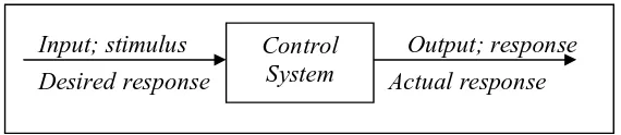
A control system consists of subsystem and processes assembled for the purpose of
controlling the outputs of the processes [2]. The air-conditioner that produces more
cool air as the result of the room temperature increase is an example. Air conditioner
use thermostat to measure the temperature of the room. Thermostat is as a subsystem
that will be the input for the system. The control system will provide an appropriate
output or response for the given input or stimulus. Figure 2.1 [2] shows the process.
Figure 2.1: Simplified Description of a Control System
7
Control system where built for four primary reasons:
a) Power amplification.
A control system can produce the needed power amplification, or
power gain. For example, a radar antenna, positioned by the
low-power rotation knob at the input, requires a large amount of low-power for
its output rotation. By using the control system, the power that needed
can be produce by amplifying the power needed.
b) Remote control.
Robot design by control system principles can compensate for human
disabilities. Control systems are also useful for remote at dangerous
location. For example, a remote controlled robot arm can be used to
pick up material in a radioactive environment.
c) Convenience of input form.
Control system can be used to provide convenience by changing the
form of the input. A temperature control system as an example. The
position on the thermostat is the input, while the output is the heat.
Thus, a convenient position input yields a desired thermal output.
d) Compensation for disturbance.
The ability to compensate for disturbance is typically to control such
variable as temperature in thermal system, position and velocity in
mechanical system, and voltage, current, or frequently in electrical
systems. The system must be able to yield the correct output even
with disturbance. For example, an antenna system that point in
position, or if noises enter internally, the system must be able to detect
the disturbance and correct the antenna’s position. The system’s input
is obviously will not change to make correction. Consequently, the
system itself must measure the amount that the disturbance has
repositioned the antenna and then return the antenna to the position
commanded by the input.
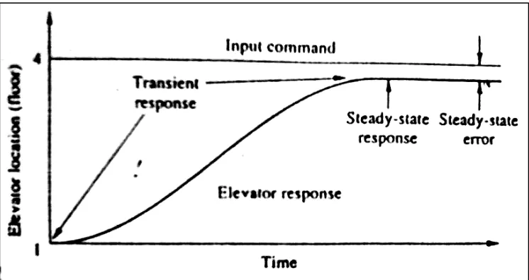
A control system provides n output or response for a given input or stimulus. The
input represents a desired response, and the output is the actual response. For
example, when the fourth-floor button of an elevator is pushed on the ground floor,
the elevator rises to the fourth-floor button of a speed and floor-leveling accuracy
designed for passenger comforts is shown in Figure 2.2 [2].