FACE DETECTION AND STEREO MATCHING ALGORITHMS FOR SMART
SURVEILLANCE SYSTEM WITH IP CAMERAS
Nurulfajar Abd Manap, Gaetano Di Caterina, John Soraghan, Vijay Sidharth, Hui Yao
CeSIP, Electronic and Electrical Engineering, University of Strathclyde, UK
ABSTRACT
In this paper, we describe a smart surveillance system to detect human faces in stereo images with applications to advanced video surveillance systems. The system utilizes two smart IP cameras to obtain the position and location of the object that is a human face. The position and location of the object are extracted from two IP cameras and subsequently transmitted to a Pan-Tilt-Zoom (PTZ) camera, which can point to the exact position in space. This work involves video analytics for estimating the location of the object in a 3D environment and transmitting its positional coordinates to the PTZ camera. The research consists of algorithm development in surveillance system including face detection, stereo matching, location estimation and implementation with ACTi PTZ camera. The final system allows the PTZ camera to track the objects and acquires images in high-resolution.
Index Terms — IP cameras, stereo vision, image
matching, object detection, intelligent systems, surveillance
1. INTRODUCTION
Smart video surveillance systems have become more important and widely used in the last few years due to the increasing demand for safety and security in many public environments [1]. There are different types of technology used for tracking and location estimation, ranging from satellite imaging to CCTV. CCTV covers limited areas and is relatively cheaper, but requires constant monitoring by additional personnel to detect suspicious activity.
The availability and cost of high resolution surveillance cameras, along with the growing need for remote controlled security, have been a major driving force in this field. A growing amount of information increases the demand on processing and tagging this information for subsequent rapid retrieval. To satisfy this demand, many researches are working to find improvements and better solutions in video analytics, which is the semantic analysis of video data, to reduce running time and total cost of surveillance systems. Video analytics for surveillance basically involves detecting and recognizing objects in an automatic, efficient fashion. In smart surveillance systems, only important data are extracted from the available video feeds and passed on for
further processing. This can save both time and storage space, and it makes video data retrieval faster, as significantly less data have to be scanned through with the use of smart tags.
Stereo matching continues to be an active research area [2,3,4]. The main aim of stereo matching is to determine disparities that indicate the difference in locating corresponding pixels. Many techniques have been proposed in order to determine the homologous points of the stereo pair [5]. Besides its application for 3D depth map, the stereo matching algorithm has been used as one of the key element in our system.
The main contribution of this paper is the presentation of a smart surveillance system for human face tracking. Multiple IP cameras have been used to obtain the 3D location of the object. Its positional information is passed to the PTZ camera to locate the targeted object. Stereo matching algorithms, normally used to obtain the depth map for 3D video and free-viewpoint video, have been exploited. They include adaptive illumination compensation, skin colour segmentation, morphological processing and region analysis.
2. SYSTEM OVERVIEW
The layout of the proposed system is shown in Figure 1, with two IP cameras and one PTZ camera, which can pan of 360°, tilt of 90° and zoom. Even if the range of view of the PTZ is quite broad, it still requires a human operator to control it, sending commands through a web-based user interface.
Figure 1. System design with two IP cameras and a PTZ camera
two fixed IP cameras are used to acquire real-time images, which are processed by the video analytics algorithms to estimate the location of the object of interest. The IP cameras capture the same scene from two different angles; therefore the two acquired video streams can be combined to produce stereo video. The 3D coordinates are computed by the stereo matching and location estimation algorithms, and then fed to the PTZ controller to point at the object location.
In this implementation, the IP cameras used are two Arecont AV3100 3.1 mega pixels, which can capture frames of 2048x1536 pixels at 15 fps. Meanwhile, the PTZ camera is a 5-mega pixels ACTi IP Speed Dome (CAM-6510). A very important feature is its capability of panning and tilting at 400° per second, which makes it very suitable for tracking. It can respond very quickly to any changes, with several movements and wide area of coverage.
The system can be divided into two main subsystems, which are the video analytics block and the controller block. In the video analytics subsystem, the algorithms employed consist of face detection, stereo matching and location estimation. The second subsystem acts as the controller for the PTZ, dealing with its hardware, firmware and protocols. The next sections discuss the two subsystems in more details.
3. VIDEO ANALYTICS ALGORITHMS
The first part of the proposed system is the video analytics block, which consists of face detection, stereo matching and location estimation algorithms.
3.1. Face Detection
The main function of this sub-block is to segment the face region out from the input image. The steps in the face detection algorithms are adaptive illumination compensation, skin colour segmentation, morphological processing and connected component analysis. For this research, the skin colour is used as main distinguishing feature in face detection. The obvious advantages of the skin colour segmentation are fast processing and high robustness to geometric variation of head pose and orientation. In this paper, the RGB colour space is chosen to explicitly define skin colour cluster boundaries and discriminate between skin/non-skin pixels, as suggested in [6].
Due to the different lighting conditions in different environments, the appearance of human skin colour can change, obviously affecting the skin region segmentation result. Therefore, the “Gray World Assumption” method [7] is used to perform adaptive illumination compensation. This method assumes that the average value of the RGB components in an image should average out to a common gray scale value. Each colour component is scaled according to the amount of its deviation from this gray value.
A skin tone model is therefore defined. The classification of skin tone is taken from research work [8, 9]. The skin colour segmentation rejects non-skin regions and retains skin regions. Morphological processing is used to reduce noise. It uses the opening operation to reject tiny object and closing operation to fill tiny holes. The connected region analysis is then performed to reject non-face regions. In this research, two geometry features of human face are examined to reject non-face regions: region ratio and roundness. The height to width ratio of human face should satisfy some specific relationship. In [10] it is mentioned that the height to width ratio of human face is around 1. Therefore, if the height to width ratio of a connected region
R satisfies 0.8 ≤ R ≤ 2.2, the region will be a candidate region for the next step.
The shape of human face can be seen as an ellipse from different angles. The roundness of a connected region can be used to reject non-face regions, according to (1):
Ci= A
i
P i2
(1)
where Ai is the area of the ith connected region, Pi is the perimeter of the ith region. If Ci >τ, with τ = 0.05, the connected region is retained for the next step.
Besides the geometry features, also holes are a useful feature to classify a skin region as a human face [6]. The idea behind this is to find a region containing at least two holes, which correspond to the two eyes. The number of holes in a connected region can be calculated by computing the Euler number of the region. It is defined as:
(2)
where E is the Euler number, C is the number of connected components and H is the total number of holes in them. In the connected region analysis, C is set to 1 because only one connected region is analyzed at a time. If the Euler number of a connected region is E < 0, the region is rejected.
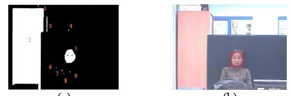
(a) (b)
Figure 2. Morphological processing and connected region analysis. (a) Image after morphological processing. (b) Region of interest
and roundness of region 2 and 3 exceed the given thresholds. Therefore, only region 5 is classified as a face region. After the analysis, the non-face regions are rejected and the coordinates of the face regions, in both left and right images, are reserved for stereo matching algorithms as shown in Figure 2(b).
3.2. Stereo Matching Algorithms
The main aim of stereo matching algorithms is to find homologous points in the stereo pair [11]. The stereo matching points are used to estimate the depth and location of the targeted objects. In the first stage, a block matching algorithm, also adopted in motion estimation, is used. The idea behind motion estimation is that the current frame is divided into several macro blocks. Then the block matching algorithm compare macro blocks in the current frame with the corresponding blocks and their adjacent neighbors in the previous frame, to create a motion vector, which describes the movement of a macro block from one location in the previous frame to the current location.
In this research, a one-step search [11] is adopted for faster execution and low complexity. A central block of human face in the left image is taken as a reference and compared with another block in the target image. The process of searching for similar matching block is constrained to 16x16 pixels for the size of macro block match, and the size of 7 pixels for the search area. The matching between reference block and the target block is determined by the value of a cost function. Here, any matching measure could be used; however, again for low computation, we use the Sum of Absolute Differences (SAD), which is given by in the following equation:
(3)
where N is the size of the macro block, Cij and Rij are the pixels of the target and reference macro block respectively.
3.3. Location Estimation Algorithms
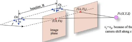
In order to calculate the accurate 3D location of the detected human face, basic geometry rules are applied. The projection of a 3D physical point onto the two image planes requires finding the exact location of the object [11]. The simplest geometry of stereo system consists of two parallel IP cameras with horizontal displacement as shown in Figure 3. The stereo configuration is derived from the pinhole camera model [12].
Referring to Figure 3, OL is the reference (i.e. left) camera centre point, while OR is the target (i.e. right) camera centre point. The implementation of this system is based on parallel cameras, which are shifted along the same horizontal line or x-axis (vL=vR). The focal length f is the distance from the camera centre point to the image plane,
while B (baseline distance) is the distance between the two optical centers, OL and OR. The disparity d of the stereo images is obtained as difference between the two corresponding points UL and UR: .
Figure 3. Stereo camera configuration
The location of correct projections of the same point PL onto the two image planes can determine the exact depth of
PL in the real world. The depth z is defined as . The equations used to calculate the exact location of
PL(X,Y,Z) for the PTZ camera controller implementation in the next section are:
(4)
4. PTZ CAMERA CONTROLLER IMPLEMENTATION
The PTZ controller module is implemented in Matlab and using the ACTi Software Development Kit (SDK), which includes acquisition of the coordinates for its conversion to pan and tilt angles for the PTZ camera. A buffer of the coordinates is created for redundancy check and to improve the performance of the tracking system. The redundancy check block also helps preventing continuous unwanted execution, also saving computation time. The output from the face detection and stereo matching in the first subsystem is used to compute pan and tilt angles and zoom factor.
The pan angle θ of the system is computed based on the model previously described in Figure 1. The PTZ camera is placed in the same x-axis as the IP camera, where L is the distance between PTZ camera and the IP camera. The angle is calculated as:
(5)
Meanwhile, the tilt angle β is computed based on the position of the PTZ camera at the same location (L, 0, 0):
5. RESULTS AND DISCUSSION
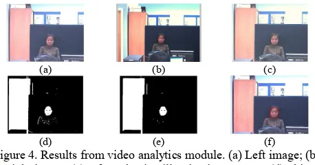
The proposed system has been developed and tested using different test vectors, by placing the cameras at different locations with respect to the PTZ, and with different people as targets. Figure 4 shows a typical result of the face detection step. The original images are shown in Figure 4(a) and 4(b), for the left and right cameras respectively. The image modified under adaptive illumination compensation algorithm is shown in Figure 4(c). The algorithm removes overcast colour lighting of the acquired images. Then it performs the skin colour segmentation process. Some parts of the image may be identified as skin, as for example objects in the background shown in Figure 4(d), where the wardrobe on the left side of the image is detected as “skin”. Morphological processing is used to eliminate/reduce noise (Figure 4(e)). The face region is selected at the end of the process (Figure 4(f)), after computing the Euler number of each detected region.
(a) (b) (c)
(d) (e) (f)
Figure 4. Results from video analytics module. (a) Left image; (b) Right image; (c) After adaptive illumination process; (d) Skin colour segmentation; (e) Morphological processing; (f) Final result
after connected region analysis.
The face detection result is processed in the block matching and location estimation step, to obtain the depth and location of the targeted object. With this information, the coordinates of the object are calculated and transmitted to PTZ camera controller. The coordinates are converted into pan and tilt angles. Figure 5(a) and 5(b) show the images acquired by the left and right cameras respectively. With the stereo matching algorithm, the depth and location of the target object is evaluated and passed to the PTZ camera. The PTZ camera initially captures the targeted object as shown in Figure 5(c). Figure 5(d) illustrates a zoomed image of the object taken by the PTZ camera, with a zoom ratio of 5, at the end of all the described steps.
(a) (b) (c) (d)
Figure 5. Image taken by the intelligence surveillance system. (a) Image taken by left IP camera; (b) Image taken by right camera; (c) The PTZ captured the targeted object; (d) The object zoom by
ratio of 5.
The testing process can be divided into three phases: testing of face detection sub-block; testing of location estimation sub-block, and execution speed analysis. For face detection testing, the publicly available IMM Face Database is used [13]. Since the skin colour segmentation is based on RGB values, the gray scale images in the database are not used. The resulting dataset contains frontal facial images of 37 individuals (both male and female): each person has associated 6 images with different facial expressions. The total number of test images is 220. For location estimation and execution speed testing, three sets of stereo images (left image and right image) have been acquired for five different individuals as targets, yielding a total number of 15 test cases.
5.1. Face Detection Test
In order to test the ability of the face detection sub-block to segment human faces from images with human skin colour as main distinguish feature, a subset of the IMM Face Database is used. From a total number of 222 facial images, 208 (93.7%) are correctly detected as containing human faces. The other 14 image faces (6.3%) are erroneously rejected because the pieces of clothing worn are segmented as “skin”, giving a value of roundness outside the margins as discussed in Section 3.1. For a further test, the face detection algorithm has also been applied to a set of stereo test images of five individuals with different skin tones: light, light intermediate, dark intermediate, dark. Five of these test images are shown in Figure 6(a) to 6(e).
(a) (b) (c) (d) (e)
Figure 6. Test images with different skin tones.
For each individual, three left images and three right images have been acquired, so that the dataset contains 30 images. By applying the face detection algorithm described in Section 3.1, the system has been able to correctly locate and segment human faces in all the test images.
5.2. Location Estimation Test
For the location estimation sub-block test, the proposed system is fed with the 15 sets of stereo images as described in Section 5.1. The main purpose of this test is to evaluate the accuracy of the target location pestimate estimated by the proposed system, with respect to the exact target location
pexact in the 3D space. The Euclidean distance between each set of estimated and exact locations is computed with . The average value of d is 0.896 m, with a standard deviation of 0.120 m.
values for each coordinate separately. It can be seen that the error in X and Y coordinates are reasonably small, while the error in Z coordinate is not negligible. The values in Table 1 clearly show that z-axes errors are the main contribution to the total error, i.e. Euclidean distance. Since the Z coordinate depends on the focal distance f and the z-axes error distribution seems to be narrow, as shown by its standard deviation, it can be assumed that this error is a bias introduced by a non exact value of f. Small errors introduced by inaccurate measurements can lead to non negligible errors in the final location estimation.
Table 1. Mean value and standard deviation of absolute differences
Axes x y z
Mean 0.058 m 0.110 m 0.885 m Standard deviation 0.014 m 0.026 m 0.122 m
5.3. Execution Time
The mean and standard deviation value of the recorded execution times are presented in Table 2. From the results, it shows that the face detection step on both images is the major contribution to execution time. The total execution time, including transmission over the network for image acquisition and PTZ command sending is approximately 0.13 seconds. This value is clearly not suitable for real-time execution at high frame rate. In the future development, the proposed system will be implemented in C, for example with OpenCV or on a dedicated DSP, which would significantly speed up the total execution time.
Table 2. Execution time statistics based on sub-block algorithms
Algorithms
Face detection (for both images)
Block matching
Location estimation
Mean 0.1065 s 0.0076 s 0.0003 s Standard
deviation 0.0018 s 0.0010 s 0.0005 s
6. CONCLUSION
A fully automated smart surveillance system has been designed and developed, that is able to detect and zoom into objects in order to acquire high quality video data. The features of this system include face detection, high quality surveillance acquisition data using PTZ camera and secure streaming of data. The system processes two images acquired from the two fixed IP cameras, as a stereo input to calculate human face locations, which can be used to control the PTZ camera to find the object. Stereo matching algorithm is used to obtain correct corresponding block in the target image that is required for accurate location estimation. The final system allows the PTZ camera to track the object and acquire images in high-resolution quality.
The proposed system has proven to be effective and fast. A major advantage is that, even with additional features, the whole system would be relatively cost effective for longer run times and could be used in real-time with additional real time programming implementation. As Ethernet and LAN connections are almost prerequisite in all large industries, the system can be integrated easily with some calibration and IP address configuration in the initial setup.
7. REFERENCES
[1] M. Valera & S. A. Velastin, “Intelligent distributed surveillance systems: a review”. Vision, Image and Signal Processing, IEE Proceedings. 192-204, 2005.
[2] L. D. Stefano, M. Marchionni & S. Mattoccia, “A Fast Area-based Stereo Matching Algorithm”. Proceedings from the 15th International Conference on Vision Interface, 2004. [3] A. Klaus, M. Sormann, & K. Karner, “Segment-Based Stereo
Matching Using Belief Propagation and a Self-Adapting Dissimilarity Measure.” Proceedings of the 18th International Conference on Pattern Recognition, 2006.
[4] S. Mattoccia, “A Locally Global Approach to Stereo Correspondence.” IEEE International Conference on Computer Vision Workshop, ICCV Workhops, 2009.
[5] D. Scharstein & R. Szeliski, “A Taxonomy and Evaluation of Dense Two-Frame Stereo Correspondence Algorithms.” International Journal of Computer Vision 47, 7-42, 2002. [6] V. Vezhnevets, V. Sazonov & A. Andreeva, “A Survey on
Pixel-Based Skin Color Detection Techniques.” Proc. Graphicon, 2003.
[7] G. Buchsbaum, “A Spatial Processor Model for Object Colour Perception.” Journal of the Franklin Institute 310, 1-26, 1980. [8] J. Kovac, P. Peer, & F. Solina, “Illumination Independent
Color-based Face Detection.” Proceedings of the 3rd International Symposium on Image and Signal Processing and Analysis.1, 510-515 Vol.1, 2003.
[9] A. Albiol, L. Torres & E. J. Delp, “Optimum Color Spaces for Skin Detection.” International Conference on Image Processing 1, 122-124 Vol.1, 2001.
[10]K. Nallaperumal, et. al. Human face detection in color images using skin color and template matching models for multimedia on the web, IFIP International Conference on Wireless and Optical Communications Networks, 2006. [11]A. Bovik, Handbook of Image and Video Processing. Elsevier
Academic Press, 2005.
[12]Y. Morvan, “Acquisition, Compression and Rendering of Depth and Texture for Multi-view Video.” Thesis PhD. Eindhoven University of Technology, 2009.