FLOW MODELLING OF NASAL CAVITY WITH VARIOUS FLOW RATE
MOHD FAIRUS FIRDAUS BIN AZMI
This report has been done In partial fulfilment for
Bachelor of Mechanical Engineering (Thermal-Fluids)
Faculty of Mechanical Engineering Universiti Teknikal Malaysia Melaka
ii
SUPERVISOR DECLARATION
“I hereby declare that I have read this thesis and in my opinion this report is sufficient in terms of scope and quality for the award of the degree of
Bachelor of Mechanical Engineering (Thermal-Fluids)”
iii
DECLARATION
“I hereby declare that the work in this report is my own except for summaries and quotations which have been duly acknowledged.”
iv
v
ACKNOWLEDGEMENT
I would like to express my gratitude to Allah and His blessing for giving me the strength to finish up this Final Year Project 1. It helps me to discover the real world of engineering project so that I can use this experience latter on in my life.
The special thank goes to my helpful project supervisor, Ms. Nur Hazwani Binti Mokhtar. The supervision and support that he gave truly help the progression and smoothness of the Final Year Project. The co-operation is much indeed appreciated.
My grateful thanks also go to Faculty of Mechanical Engineering (FKM). I am also will like to thankful the Coordinator of Final Year Project, Fudhail Bin Abdul Munir, and all the lecture and staff in the FKM office that patient in helping me complete this project.
vi
ABSTRACT
Nasal cavity is one of the organs in the human respiration system. Nasal cavity acts as the air flow passage for human ventilation and respiration. The unique geometry of nasal cavity can change the flow behaviour and the flow pattern of air throughout the nasal cavity. This project use to understand the effect and behaviour of air inside the nasal cavity. The project used three inhale breathing condition which is passive, moderate and active breathing. To get the simulation result, the study use an actual human 3D model of the nasal cavity and been added with several boundary conditions into the Engineering Fluid Dynamic (EFD) software. The mesh size that has been used in this study is 0.001m. Before the simulation and analyse process was started, the actual human 3D model of nasal cavity has been validated. The 3D model been compare with the previous study data to make sure that the data that have obtain are valid to use for further study. The results gained from this study are, the geometry have influence the value of velocity and pressure of air that flow inside the nasal cavity. For passive and moderate breathing the air inside the nasal cavity were at laminar state all the time. For active breathing the first half of the nasal cavity the air was at turbulent state, then for the last half of the nasal cavity the air was in the laminar state.
vii
ABSTRAK
viii
TABLE OF CONTENTS
CHAPTER CONTENT PAGE
ADMISSION ii
DEDICATION iv
ACKNOWLEDGEMENT v
ABSTRACT vi
ABSTRAK vii
CONTENTS viii
LIST OF TABLE xi
LIST OF FIGURE xii
LIST OF SYMBOL xvi
LIST OF APPENDIX xvii
CHAPTER I INTRODUCTION 1
1.1 Project Background Study 1
1.2 Problem Statement 2
1.3 Project Objective 3
1.4 Project Scope 3
CHAPTER II LITERATURE REVIEW 4
2.1 Nasal Cavity 4
2.1.1 Nasal Valve 5
2.1.2 Turbinates 6
ix
CHAPTER CONTENT PAGE
2.1.4 Olfactory 8
2.1.5 Inhalation Process 9
2.3 Previous Study 10
2.2.1 Experimental Method 10
2.2.2 Simulation Method 12
2.2.3 Flow Pattern 13
2.2.4 Geometry 14
2.2.5 Pressure 15
2. 2.6 Velocities 16
CHAPTER III METHODOLOGY 17
3.1 Model Reconstruction 17
3.1.1 CT Scan and MRI 17
3.1.2 Threshold Separation 18
3.1.3 Editing Mask 19
3.1.4 Morphology Operation 20
3.1.5 Boolean Operation 21
3.1.6 Patching Operation 22 3.1.7 Reduce Number of Faces 24
3.1.8 .STL Format 25
3.2 Fluid Flow Theories 27
3.2.1 Incompressible Flow 27 3.2.2 Governing Equation 28 3.2.2.1 Navier-Stokes 28
Equations
3.2.2.2 Reynolds Averaged 29 Navier-Stokes Equations
3.3 Type of Flow and Boundary 29
Condition
x
CHAPTER CONTENT PAGE
CHAPTER IV RESULT AND DISCUSSION 32
4.1 Introduction 32
4.2 Grid Independent 33
4.3 Model Validation 34
4.4 Velocity 36
4.4.1 Result 36
4.4.2 Discussion 39
4.5 Pressure 42
4.5.1 Result 42
4.5.2 Discussion 45
4.6 Flow Pattern 48
4.6.1 Result 48
4.6.2 Discussion 50
CHAPTER V CONCLUSION AND RECOMMENDATIONS 53
5.1 Conclusion 53
5.2 Recommendations 55
REFERENCES 56
BIBLIOGRAPHY 58
xi
LIST OF TABLE
NO. TITLE PAGE
3.1 Boundary Condition 30
xii
LIST OF FIGURE
NO. TITLE PAGE
2.1 The overview of the nasal cavity area 5
(http://www.edoctoronline.com
/medical-atlas.asp?c=4&id=21657)
2.2 Turbinates part in nasal cavity area 6
(http://emptynosesyndrome.org/images/turbinates.jpg)
2.3 Location of nasopharynx 7
(http://upload.wikimedia.org/wikipedia/commons/ thumb/4/4a/Illu_pharynx.jpg/250px-Illu_pharynx.jpg)
2.4 Location of the olfactory in nasal cavity 8 (http://library.thinkquest.org/05aug/
00386/smell/neus.jpg)
2.5 The 3D actual model 11
(Source: Xu, C. 2005)
2.6 The ETA Model 12
(Source: Ball, C.G. 2007)
2.7 Surface definition of the nose model obtained 13 from Computed Tomography
xiii
NO. TITLE PAGE
2.8 Sketches of a coronal cross section on the left side 14 and principal sketch of the DPIV setup and the optical
arrangement on the right side (Source: Horschler, I. 2005)
2.9 Comparison of streamline patterns 15
(Source: Hrorschler, I. 2009)
2.10 (a) Lateral view of the nasal cavity model showing 16 the left cavity side
(b) Lateral view of the 90º bend pipe (Source: Inthavong, K. 2010)
3.1 The CT scan of nasal cavity 18
(http://gapyx.com/cmt/2008/01/ coronal_ct_scan_eyes_conchae.jpg)
3.2 Image human nasal import in AMIRA 18
3.3 Numerical model after edited and remeshed process 19
3.4 Category of model generated on morphology 20 operation
3.5 Result of morphology operation model 20
3.6 Category of model generated on Boolean operation 21
3.7 3-D numerical nasal walls generated successful 21 after Boolean operation
xiv
NO. TITLE PAGE
3.9 Numerical model in MAGICS 22
3.10 Face of Profile Model Was Deleted 23
For Modified Process
3.11 Face of profile model was deleted 23
for modified process
3.12 Patching hole created 24
3.13 Generated model transferred in AMIRA 24
3.14 Numerical model in SolidWork 25
3.15 Flow chart of model reconstruction 26
3.16 Numerical Solving Process 31
4.1 Graph of velocity vs. length for determine 33 meshing size
4.2 Graph of area vs. length for model validation 35
4.3 Graph of velocity vs. length for various flow rates 38
4.4 Nasal cavity 3D model 40
4.5 The flow trajectory of passive breathing 40
4.6 The flow trajectory of moderate breathing 41
xv
NO. TITLE PAGE
4.8 Graph of pressure vs. length for various flow rates 43
4.9 Bar chart of pressure difference of various flow rates 44
4.10 Nasal cavity 3d model 46
4.11 The pressure flow trajectory of passive breathing 46
4.12 The pressure flow trajectory of moderate breathing 47
4.13 The pressure flow trajectory of active breathing 47
4.14 Graph of Reynolds number versus axial length 49
4.15 Air flow for passive breathing 51
4.15 Air flow for moderate breathing 52
xvi
LIST OF SYMBOL
Re = Reynolds Number
ρ = Density, kg/m3
µ = Dynamic viscosity, kg/ms
�̇ = Volume Flow Rate, lpm
Ma = March Number
v = Speed, m/s
xvii
LIST OF APPENDIX
NO. TITLE PAGE
A Project Flow Chart 66
B PSM1 Gantt Chart 67
C PSM2 Gantt Chart 68
D Simulation Setup 69
E Data of passive breathing 73
F Data of moderate breathing 74
G Data of Passive breathing 75
1
CHAPTER 1
INTRODUCTION
1.1 Project Background Study
Nasal cavity is an important organ in the respiration system. The nasal cavity acts as an air flow passage for human ventilation and respiration. When airs enter nasal cavity, flow behaviour and flow pattern of air in nasal will change due the unique geometry inside the nasal cavity. To understand the effect of flow behaviour in nasal cavity, the numerical method is use.
2
There are several factors that can influence the air flow pattern inside the nasal cavity. First factor is the unique geometry inside the nasal cavity. The geometry can increase and decrease the velocity and pressure of the air flow inside the nasal cavity. Second factor is the pressure difference of the inlet and the outlet of the nasal cavity. The pressure difference can influence the airflow nasal cavity. The relation is the higher pressure difference of the inlet and outlet of nasal cavity, the higher the velocity of the air flow inside the nasal cavity.
This study will simulate and analyse the air flow behaviours during inhalation with various breathing condition. The various breathing state is in three states, first is at passive condition such as sleeping and resting where the flow rate of air is at 5 lpm, second is at moderate condition such as studying and driving where the flow rate of air is at 12 lpm and third is at active condition such as exercising and doing sport activity where the flow rate of air is at 40 lpm.
1.2 Problem Statement
3
The Nasal cavity acts as an air flow passage for human ventilation and respiration. Within the nasal cavity, air is warmed and filtered before joining the throat and trachea. Knowledge of the airflow field in nasal cavities is essential to understand the basic functions of the nose, such as air transportation and odorant sensation. This study will simulate and analyse the air flow behaviours during inhalation with various breathing condition.
1.3 Project Objective
The objective of this study is to simulate and analyses the air flow pattern in nasal cavity during inhalation with various breathing condition
1.4 Project Scope
The scopes of this project are:
1. Simulate the air flow pattern during inhalation by various breathing condition by using EFD software (SolidWork Cosmos Floworks 2008) and MATLAB 2008.
4
CHAPTER II
LITERATURE REVIEW
2.1 Nasal Cavity
5
Figure 2.1: The overview of the nasal cavity area
2.1.1 Nasal Valve
6
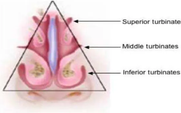
2.1.2 Turbinates
Turbinate is a curve, thin and bony plate that starts from the walls of nasal cavity and go through to the respirator passageways. The turbinate can be divided into 3 parts which is superior turbinates, middle turbinates and inferior turbinates as show in Figure 2.2.
[image:23.612.176.471.445.629.2]From the three parts the turbinate superior turbinates is the smallest and inferior turbinates is the largest of the 3 part of the turbinates. In the turbinates, the air are prepare before it enter the lungs and help to feed the perceive airflow to the lung. In the turbinates they are mucous tissues that have a combine of capillary vessels, olfactory nerve, nerve terminals and gland cell that use to smell and breath. From this, when it cold the mucous tissues will enlarge and narrow the nasal airways to heat up the air. The process calls nasal obstruction [2]. The dimensions of the turbinates in the nasal are about 40 mm high, 1-3 mm wide, and approximately 60 mm deep.
7
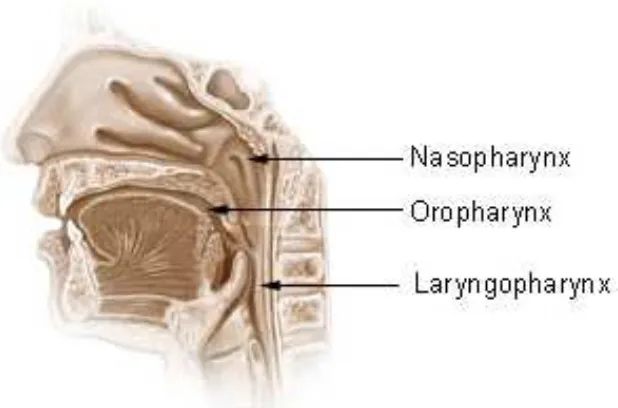
2.1.3 Nasopharynx
[image:24.612.231.540.283.487.2]Figure 2.3 shows the location of nasopharynx. The nasopharynx is the last part of nasal passage ways that located at top part of the throat or pharynx. It provides a passage way to airflow to other pharynx component and trough to the lungs. The nasopharynx is also coordinating the airflow during the eating. This will not let any food or drinks will enter the respiration line. It also uses to trap and kills bacteria that have in the surround air [3].