ii
SUPERVISOR DECLARATION
“I hereby declare that I have read this thesis and in my opinion this report is sufficient in terms of scope and quality for the award of the degree of Bachelor
of Mechanical Engineering (Automotive)
DESIGN AND ANALYSIS OF A LIGHTWEIGHT CLUTCH DISC FOR A SINGLE SEATED RACE CAR
MUHAMAD HAZWAN BIN MOHDZAHRI
This thesis is submitted to
fulfill a part of the requirement from the terms of graduation of Bachelor of Mechanical Engineering (Automotive)
Faculty of Mechanical Engineering Universiti Teknikal Malaysia Melaka
iii
DECLARATION
“I hereby declare that the work in this report is my own except for summaries and quaotations which have been duly acknowledged”
Signature: ………
Author: ………
iv
ACKNOWLEDGEMENT
Thank you Allah for his blessings because with His permission and divine guidance, I have successfully completed my Projek Sarjana Muda and this report. First of all I would like to thank my supervisor, Mr. Fudhail B. Abd Munir for his guidance through this project
I would also like to thank my family for giving me encouragement to continue my studies, as also to the lecturers at Universiti Teknikal Malaysia Melaka and all my friends that know me especially for those who living at our mansion at Taman Sutera Wangi. You guys have been giving me a good help for completing this report.
I also like to thank Universiti Teknikal Malaysia Melaka for providing enough equipments and source of materials. Lastly, I would like to thank all who are involved either directly or indirectly in my Projek Sarjana Muda 1 and provides support until I complete this report. Thank you for all that was cooperating in this Projek Sarjana Muda at University Teknikal Malaysia Melaka.
v
ABSTRAK
vi
ABSTRACT
vii
TABLE OF CONTENTS
PAGE
SUPERVISOR DECLARATION ii
DECLARATION iii
ACKNOWLEDGEMENT iv
ABSTRAK v
ABSTRACT vi
TABLE OF CONTENTS vii-ix
LIST OF FIGURES x-xii
LIST ,OF TABLES xiii
LIST OF SYMBOLS xiv
CHAPTER 1: INTRODUCTION
1.1 PROJECT BACKGROUND 1
viii
1.3 PROBLEM STATEMENT 2
1.4 SCOPE 3
CHAPTER 2: LITERATURE REVIEW
2.1 CLUTCH 4-5
2.1.1 Flywheel 5-6
2.1.2 Clutch Disc 6
2.1.3 Pressure Plate 7
2.1.4 Release Bearing 8
2.1.5 Linkage 8-10
2.2 THEORY OF HEAT TRANSFER 10
2.2.1 Conduction 11
2.2.2 Convection 12-13
2.2.3 Radiation 13-14
2.3 HEAT TRANSFER FORMULATION IN FINITE ELEMENT
2.3.1 Thermal Steady State 15-16
2.3.2 Thermal Transient 16-17
2.4 THERMAL BEHAVIOR OF AUTOMOTIVE FRICTION CLUTCH 17-19
2.5 THERMAL ANALYSIS PROCEDURES 19-20
2.6 CARBON-CARBON COMPOSITE
ix
2.6.2 Manufacturing Process 22-23
2.6.3 Properties 24
Chapter 3: METHODOLOGY
3.1 INTRODUCTIONS 25
3.2 METHOD OF CALCULATION 26
3.2.1 Calculating The Clutch Disc Diameter 27-28 3.2.2 Calculating The Axial Force, 29
3.3.3 Designing The Clutch Hub 29-32
3.3 METHOD OF MATERIAL COMPARISON 32-33
3.4 METHOD OF DESIGN 33
3.5 METHOD OF FINITE ELEMENT ANALYSIS 34
CHAPTER 4: ANALYSIS AND RESULT
4.1 STATIC STRUCTURAL ANALYSIS USING ANSYS 35-36
4.1.1 Finite Element Meshing 36
4.1.2 Applying Boundary Conditions 37-38 4.1.3 Define the Material Properties 38
4.2 RESULT 39
4.2.1 Distribution of Von-Misses Stress 39
4.2.2 Total Deformation 40
x
CHAPTER 5: DISCUSSION
5.1 Von-Misses Stress Distribution 42
5.2 Comparison between Asbestos and Carbon-Carbon Composite 43 Material
CHAPTER 6: CONCLUSION AND RECOMMENDATION
6.1 Conclusion 44-45
6.2 Recommendations 45
REFERENCES 46-49
xi
LIST OF FIGURES
NO. TITLE PAGE
1. Figure 1: Clutch system assembly 5
2. Figure 2: Flywheel 6
3. Figure 3: Clutch disc 6
4. Figure 4: Pressure plate 7
5. Figure 5: Throw-out bearing 8
6. Figure 6: Clutch linkage 10
7. Figure 7: Manufacturing Process of Carbon-Carbon Composites 23
8. Figure 8: Clutch disc diameter 26
9. Figure 9: Straight sided spline hub 30
10. Figure 10: Clutch Disc Assembly 33
xii
12. Figure 12: Force Applied Onto Clutch Facing 37
13. Figure 13: Fixed Support 38
14. Figure 14: Von Misses Stress Distribution 39
xiii
LIST OF TABLES
NO. TITLE PAGE
1. Table 1: Properties of Carbon-Carbon Composites 24 2. Table 2: Table of coefficient of Carbon-Carbon Composites 24 3. Table 3: Mechanical Properties of Carbon-Carbon Composite 38 4. Table 4: Thermal Properties of Carbon-Carbon Composite 38 5. Weight comparison between asbestos and carbon-carbon composite 41
xiv
LIST OF SYMBOLS
T = torque transmitted, Nm
= maximum pressure applied onto the clutch disc, Pascal F = coefficient of friction (it depends on the material used)
= outer radius diameter, mm = inner radius diameter, mm N = number of friction surface
= axial force
= circumferential force
= height, mm
= bearing pressure
1
CHAPTER 1
INTRODUCTION
1.1 PROJECT BACKGROUND
2
1.1 PROJECT OBJECTIVE
This project objective is to design a lightweight clutch disc for a single seated race vehicle and to analyze the clutch disc design by using FEM software. The 1st objective can be achieved by calculating the diameter of the clutch disc and the hub length by using formula. The 2nd objective can be achieved by using ANSYS software. In this software, a simulation test will be done to the clutch disc
1.2 PROBLEM STATEMENT
The first problem that occurs when designing a clutch disc for a race car is its ability to transfer the engine torque to the transmission system and to the wheels. A race car engine produces high torque, so the clutch system for this type of car must be able to deliver the torque from the engine to the transmission system. So, an optimum clutch disc diameter for this engine must be calculated to make sure that it will not result in failure of clutch system.
3
1.3 PROJECT SCOPE
The first project scope is to design a lightweight clutch disc based on SAE formula engine specification which the Mc Master SAE team is chosen. The Mc Master SAE team use Honda CBR 600 Fi engine. This engine produces maximum torque of 65 Nm.
The second project scope is to complete the technical drawing of the clutch disc by using CATIA software.
4
CHAPTER 2
LITERATURE REVIEW
2.1 CLUTCH
5
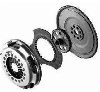
minimized by the proper alignment of engine and transmission/transaxle and of the clutch components. The clutch system is located between the engine and the transmission. Clutch system basically consists of six major parts which are flywheel, diaphragm spring, clutch disc, pressure plate, clutch cover and linkage that is necessary to operate the clutch (Derek. N & Allan. B. 2000)
Figure 1: clutch system assembly (Jack, E. 2005)
2.1.1 Flywheel
6
Figure 2: flywheel (Jack, E. 2005)
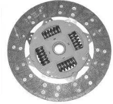
2.1.2 Clutch Disc
The clutch disc receives the rotating motion from the flywheel and transfer the motion to the transmission input shaft (Derek. N & Allan. B. 2000). A clutch disc comprise of grey cast iron counter mate disc, friction facing, and cushioning springs. The friction facing is the main component in contact with the flywheel, and provides the required friction force to maintain that contact. It is either riveted or bonded to the disc. The cushioning spring, or torsion springs, cause the contact pressure of the facings to rise gradually as the springs flatten out when the clutch is engage. It also eliminates chatter during engagement and avoiding the flywheel and pressure plate sticking to the clutch disc when disengaging the clutch.
7
2.1.3 Pressure Plate
The pressure plate squeezes the clutch disc onto the flywheel when the clutch disc is engaged and moves away from the disc when the clutch pedal is depressed. These actions allow the clutch disc to transmit or not transmit the engine’s torque to the transmission system. A pressure plate is basically a large spring loaded clamp that is bolted to and rotates with the flywheel. A pressure plate assembly includes a sheet metal cover, heavy release spring, a metal pressure ring that provides a friction surface for the clutch disc, a thrust ring or fingers for the release bearing and a release levers. The release leavers release the holding force of the springs when the clutch is disengaged. The spring used in most pressure plate is Belleville spring or diaphragm spring.
8
2.1.4 Release Bearing
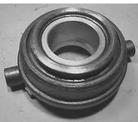
The release bearing is a ball type bearing located in the bell housing and operated by the clutch linkage. Release bearing are usually sealed and pre lubricated to provide smooth and quiet operation as they move against the pressure plate to disengage the clutch (Derek. N & Allan. B. 2000). When the clutch pedal is depressed to disengage the clutch, the release bearing moves toward the flywheel, depressing the pressure plate’s release fingers or thrust pad and moving the pressure plate fingers or lever against pressure plate spring force. This action moves the pressure plate away from the clutch disc. A clutch release bearing is often referred as throw-out bearing.
Figure 5: throw-out bearing (Derek, N & Allan, B. 2000)
2.1.5 Linkage
9
a release lever and rod, an equalizer or cross shaft, a pedal to equalizer rod, an assist or over center spring and the pedal assembly. Depressing the pedal moves the equalizer that in turn, moves the release rod. When the pedal is released, the assist spring returns the linkage to its normal position and removes the pressure on the release rod. This action causes the release bearing to move away from the pressure plate.
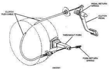
A cable-type clutch linkage is simple and, lightweight. Normally the cable connects the pivot of the clutch pedal directly to the release fork. This simple set-up is compact, flexible and eliminates the wearing pivot points of a shaft and lever linkage. However, cables will gradually stretch and can break due to electrolysis. Typically, one end of the cable is connected to the pedal assembly. At the assembly is located a spring that keeps the pedal in the up position. The cable is held under tension by the spring and a cable stop located on the fire wall. The other end of the cable is connected to the outer end of the clutch release fork. This end is threaded and fitted with an adjusting nut and locknut that allows for pedal free play adjustments. When the clutch pedal is depressed, the cable pulls on the clutch fork, which causes the release bearing to move against the pressure plate (Jack. E. 2005).
A hydraulic linkage consists of a master cylinder, hydraulic tubing and slave cylinder. The master cylinder is attached to and activated by the clutch pedal through the use of an actuator rod. The slave cylinder is connected to the master cylinder by flexible pressure hose or metal tubing. The slave cylinder is positioned so that it can work directly on the clutch release yoke lever. Depressing the clutch pedal pushes the actuator rod into the bore of the master cylinder. This faction forces a plunger or piston up the bore of the master cylinder. During the initial 1/32 inch of pedal travel, the valve seal at the end of the master cylinder bore closes to the port to the fluid reservoir. As the pedal is further depressed, the movement of the plunger forces fluid from the master cylinder through a line to the slave cylinder. This fluid is under pressure and causes the piston of
the slave cylinder to move. Movement of the slave cylinder’s piston causes its push rod
10
Figure 6: clutch linkage (Jack, E. 2005)