STUDY OF ENERGY REGENERATIVE SUSPENSION SYSTEM FOR VEHICLE
RAHIMAN SALMI BIN ROSDI
“This report is prepared in fulfillment for awarding the Degree of Bachelor Mechanical Engineering (Design and Innovation)”.
SUPERVISOR DECLARATION
“I hereby declare that I have read this thesis and in my opinion this report is sufficient in terms of scope and quality for the award of the degree of Bachelor of Mechanical Engineering (Design
and Innovation).”
Signature : ………
Supervisor : ………
i
DECLARATION
“I hereby declare that the work in this report is my own except for summaries and quotations which have been duly acknowledged.”
Signature : ………
Author : ………
iii
ACKNOWLEDGMENT
ABSTRACT
This Final Year Project, the research is to study the reliability and to analyze the energy harvest from vehicle suspension system. The regenerative suspension system (RSS) is a device that converts the kinetic energy of an oscillating object into electric energy. Normally, this kinetic energy is dumped in a form of thermal energy in a conventional of mechanical shock absorber
v
ABSTRAK
Di dalam Projek Akhir Tahun untuk semester kali ini, kajian yang dibuat adalah untuk mengkaji kebolehpercayaan dan menganalisis untuk mendapatkan tenaga daripada sistem suspensi kenderaan. Sistem Penjanaan Suspensi (SPS) adalah satu alat yang menukarkan tenaga kinetik menjadi tenaga elektrik. Biasanya, tenaga kinetik dibuang dalam bentuk tenaga haba.
vii
LIST OF TABLE
No. TITLE PAGE
3.1 The description for better close-up about 33 each RSS device.
3.2 An estimation cost and uses of material. 34 4.1 The maximum voltage from each graph for two 50
ix
LIST OF FIGURE
No. TITLE PAGE
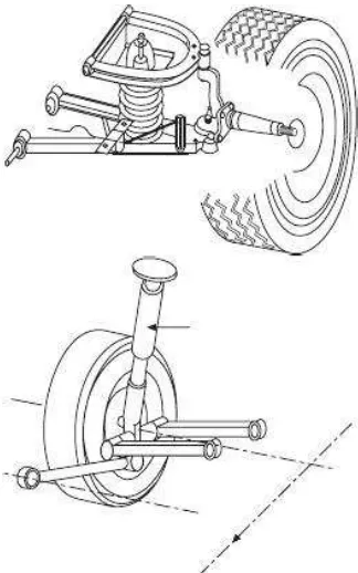
2.1 Double Wishbone 8
2.2 Multi-link suspensions. This system the spring 9 in red color is separate from the shock absorber in
yellow color
2.3 Strut suspension 10
2.4 An Air suspension 11
2.5 Bose Acoustic suspensions 12
2.6 The Neodymium iron boron (NdFeB) 16
3.1 A flow chart for Final Year Project 27
3.2 The first concept design of the RSS 29
that call as “RSS1”
3.3 The “RSS 1” attach to shock absorber 29
that call as “RSS2”.
3.5 The “RSS 2” attach to shock absorber 31
3.6 The “RSS3” with numbering for 32
each component
3.7 Full installation of the device to the 36
shock absorber
3.8 The installation of shock absorber to the 37 shock absorber tester
3.9 The finish step of placing the shock absorber to 37
the shock absorber tester
3.10 Step of testing the current flow using multi-meter 38 3.11 The device called as speedometer to run the shock 38
absorber tester
4.1 The product finish that is called as “RSS 3” 41 4.2 Voltage produced using diameter of copper coil 42
D = 0.08 mm at 10 Hz
4.3 Voltage produced using diameter of copper coil 43 D = 0.05 mm at 10 Hz
4.4 Voltage produced using diameter of copper coil 44 D = 0.08 mm at 20 Hz
xi
D = 0.05 mm at 20 Hz
4.6 Voltage produced using diameter of copper coil 46 D = 0.08 mm at 30 Hz
4.7 Voltage produced using diameter of copper coil 46 D = 0.05 mm at 30 Hz
4.8 Voltage produced using diameter of copper coil 47 D = 0.08 mm at 40 Hz
4.9 Voltage produced using diameter of copper coil 48 D = 0.05 mm at 40 Hz
4.10 Voltage produced using diameter of copper coil 49 D = 0.08 mm at 50 Hz
4.11 Voltage produced using diameter of copper coil 49 D = 0.05 mm at 50 Hz
CONTENTS
CHAPTER TOPIC PAGES
DECLARATION i
DEDICATION ii
ACKNOWLEDGEMENT iii
ABSTRACT v
LIST OF TABLE viii
LIST OF FIGURE ix
CHAPTER 1 INTRODUCTION 1
1.0 INTRODUCTION 1
1.1 OBJECTIVE 2
1.2 SCOPE OF PROJECT 3
1.3 PROBLEM STATEMENT 3
2.0 INTRODUCTION 4
2.1 SUSPENSION SYSTEM 5
2.1.1 Function of Suspension system 5 2.1.2 Work Principle of Suspension System 6 2.1.3 Type of Suspension System 6 2.1.3.1 Double Wishbone suspension 7 2.1.3.2 Multi-link suspension 8
2.1.3.3 Strut suspension 9
2.1.3.4 Air suspension 11
2.1.3.5 Bose Acoustic suspension 12
2.2 ELECTROMAGNET 13
2.2.1 Introduction of Faraday’s Law 13
2.2.2 Faraday’s Law Principle 14
2.3 MATERIALS TO USE 15
2.3.1 Magnet 15
2.3.1.1 Introduction of magnet 15
2.3.1.2 Types of Magnet 16
2.3.2 Coated Coil 17
2.3.3 Aluminum 17
3.0 INTRODUCTION 25
3.1 FLOW CHART 26
3.2 CONCEPTUAL DESIGN 28
3.2.1 RSS 1 28
3.2.2 RSS 2 30
3.2.3 RSS 3 31
3.3 MATERIALS 34
3.3.1 List of Materials Cost 34
3.4 EXPERIMENTING PROCEDURE 35
CHAPTER 4 RESULTS 40
4.0 FINISHING PRODUCT 40
4.1 EXPERIMENTAL DATA 42
CHAPTER 5 DISCUSSION 52
5.0 DISCUSSION 52
CHAPTER 6 CONCLUSION AND RECCOMENDATION 54
6.0 CONCLUSION 54
6.1 RECOMMENDATION 55
1
CHAPTER 1
INTRODUCTION
1.0 INTRODUCTION
Shocks absorbers are used to reduce oscillation by absorbing the energy contained in the springs or torsion bars when the wheels of an automobile move up and down. Regular shock absorbers do not support vehicle weight. They lower the dynamic wheel-load changes and avoid the wheels from lifting off the road surface except on extremely rough surfaces and making possible much more careful steering and braking. The shock absorbers turn the kinetic energy of suspension movement into thermal energy or heat energy to be dissipated within the hydraulic fluid. Still, this kind of kinetic energy can be converted into electric energy which in chance can be stored in a battery. It is potential if RSS is used. This is particularly essential if an electric vehicle is considered. The overall efficiency of the electric drive is getting higher by converting the oscillation energy and storing it in the battery. On at a time the energy causes to the extension of the travelling distance under the single charge. Up to now there has no a qualitative proportional study of various types of RSS and a selection of the most suitable design. The design calculations approach in use to determine the main design parameters of the selected version. To determine its electromechanical performance by simulate the dynamics of RSS.
1.1 OBJECTIVE
3
1.2 SCOPE OF PROJECT
This project consists of design, analysis and fabricates the regenerative system for the scope of the project.
1.3 PROBLEM STATEMENT
CHAPTER 2
LITERATURE REVIEW
2.0 INTRODUCTION
5
will discuss the reliability of the regeneration of energy from the suspension system for ground vehicles. In this system, the use of magnets and coils will help to produce energy regeneration to convert mechanical energy generated to the beneficial energy of electricity.
2.1 SUSPENSION SYSTEM
2.1.1 Function of Suspension System
impact and dissipate kinetic energy. Shock absorber valves oil and gas to absorb the excess energy resulting from the spring.
2.1.2 Work Principle of Suspension System
When the vehicle violates hump, moving through the road surface is cracked or broken, it will cause the tire to move down and angled up from the road surface. The magnitude of the movement depends on whether the breach with a large humps or fine detail. Without a dominant structure, the resulting total energy will flow to the vehicle frame moving in the same direction. In this situation, the tires may lose control and not in contact with the road surface as a whole. Then, the gravitational pull of facing down will cause shock between the tire and road surface. Function of the suspension system in this situation is to absorb the energy and vibration of the resulting shock, and ensure the vehicle body frame and move without being interrupted when the vehicle through the bumps on the road.
2.1.3 Types of Suspension System
7
are more exposed to rough terrains. Likewise, these are also applied to vehicles that are designed to carry cargos or passengers. Excess shocks give support for vehicles that are go through suspension problems both in the front or rear systems. Overload shocks are perfect for those that suffer from under steering. An air shock is a common feature of cargo trucks and other vehicles that tend to carry massive weight or load. There are five types of suspension which are Double Wishbone, Multi-link, Strut, Air Suspension and Bose Acoustic (Johnny Schultz, 2011).
2.1.3.1 Double Wishbone suspension
Figure 2.1 Double Wishbones (Julian Happian-Smith, 2002)
2.1.3.2 Multi-link suspension