DEVELOPMENT OF OPEN SYSTEM AND APPLICATION MOBILE
PLATFORM FOR ALL TERRAIN LOCOMOTION
AHMAD YUSAIRI BIN BANI HASHIM
FAKULTI KEJURUTERAAN PEMBUATAN UNIVERSITI TEKNIKAL MALAYSIA MELAKA
2013
DEVELOPMENT OF OPEN SYSTEM AND APPLICATION MOBILE
PLATFORM FOR ALL TERRAIN LOCOMOTION
AHMAD YUSAIRI BIN BANI HASHIM
RESEARCH VOTE NO: S00872 PJP/2011/FKP(5C)
FAKULTI KEJURUTERAAN PEMBUATAN UNIVERSITI TEKNIKAL MALAYSIA MELAKA
ABSTRACT
DEVELOPMENT OF OPEN SYSTEM AND APPLICATION MOBILE
PLATFORM FOR ALL TERRAIN LOCOMOTION
(Keywords: Shrimp robot, Graph, Reaction force, Locomotion)
Mobile robots with shrimp design are known to be ever changing when climbing or working under rugged terrains. Because of its sturdiness, robots with shrimp configuration will be able to perform complicated tasks. This work reproduced a mobile robot with shrimp design as proposed by Siegwart. A conventional shrimp robot has six wheels. Its structural complexity results in a perception that it is a hard-to-build robot. For straightforwardness, our shrimp rover is signified by a graph. The working volume for the platform is (678 by 350 by 525) cubic millimeter, with the exception of the front and rear forks' dimensions. It has a platform module attached to two forks, at front and rear, respectively. The forks have extra suspensions, whereas the platform relies on the suspension given by the wheels. Gyroscopic consequences on the rover are due to area surface conditions. The gyroscopic effects can be analyzed by computing the joint angles and change in heights all through rover maneuver. The products of the joint angles and change in the heights represent membership functions, which values are within certain limits. Therefore, the limits for the membership function values are the determinant circumstance for predicting the rover's stability if it will ever flip through.
Key researchers:
Ahmad Yusairi bin Bani Hashim (Head) Mohd Nazrin bin Muhammad (FKP)
Khairol Anuar bin Rakiman (FKP) Zamberi bin Jamaludin (FKP) E-mail: [email protected]
Tel.No.: 06-2333431
ACKNOWLEDGMENT
TABLE OF CONTENTS
ABSTRACT ...III ACKNOWLEDGMENT ... IV TABLE OF CONTENTS ... V LIST OF FIGURES ... VII LIST OF TABLES ... VIII
INTRODUCTION ... 1
1.1 Overview ... 1
1.2 Problem Statements ... 3
1.3 Objective ... 3
1.4 Scope ... 4
LITERATURE REVIEW ... 5
2.1 Overview ... 5
2.2 Cockroach Robots ... 6
2.2.1 InsBot ... 6
2.2.2 Cockroach-inpired Hexapod Robot ... 7
2.3 Six-legged robot with security function... 8
2.4 Shrimp Robot ... 9
2.4.1 The Configuration ... 9
2.4.2 The Kinematics ...10
METHODOLOGY ...12
3.1 Overview ...12
3.2 Theoretical Outline ...12
3.2.1 Graph Representation ...12
3.3 Design of the Mobile Platform ...15
RESULTS AND DISCUSSIONS ...17
4.1 Overview ...17
4.2 The Roving Model ...18
4.3 Maneuverability Simulation ...19
4.4 Decision Rules for Maneuverability ...23
CONCLUSIONS ...26
LIST OF FIGURES
Figure 1. InsBot (adapted from [9]) ... 7
Figure 2. Prototype of the LIPCA robot (adapted from [10]) ... 8
Figure 3. A six-legged robot (adapted from [11]) ... 8
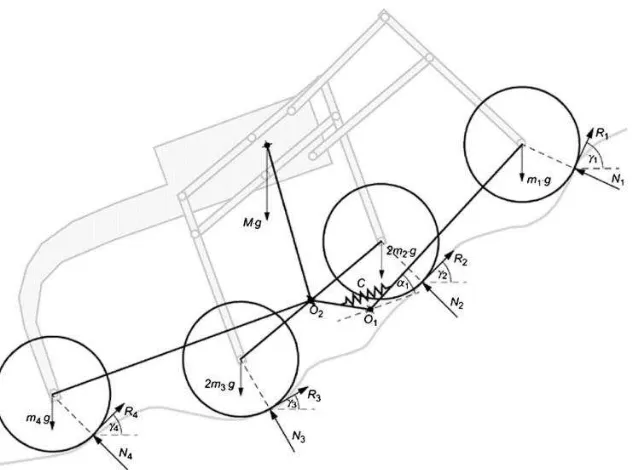
Figure 4. A simplified model of shrimp robot that shows field reaction forces acting on the wheels. These forces resulted in the joints' responses where the robot will configure to accommodate in keeping with the field structure (adapted from [2]) ...10
Figure 5. A simplified model of shrimp robot that is represented by a rooted graph ..13
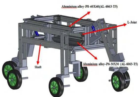
Figure 6. The materials and parts used to construct the rover’s structure ...16
Figure 7. Realization of the rover ...17
Figure 8. Testing for structural durability by common sense ...17
Figure 9. Simulation of a stair climbing and descending movement ...18
Figure 10. Condition of a stair climbing and descending movement...19
Figure 11. Maneuvering over selected ground surface profiles ...20
LIST OF TABLES
INTRODUCTION
1.1 Overview
Mobile robots with shrimp design are known to be dynamic when climbing or working under rough terrains. Due to its sturdiness, robots with shrimp configuration will be able to perform difficult tasks that involved rough terrains. Tunnel power cables, for example, has a rigor environment condition. a conventional mobile robot couldn't be able to maneuver effectively under this circumstance. Sonyi et al. [1] used a shrimp rover to monitor tunnel power cables where it collects real-time information about the aging status of tunnel power cables during operation. The shrimp robot design is inspired from existing rover concepts. However, its main difference is the extended use of parallel suspension architectures leading to a very smooth slope of the center of gravity even when overcoming obstacles with vertical slopes. The robot is therefore able to move in very rough terrain with minimal motor power although the friction coefficient with the ground is relatively low [2].
The passive locomotion mechanisms need fewer sensors and actuators than active ones, and do not require active transformation to fit the terrain. Thus, they are much easier to control. Conversely, the traditional mobile robots do have some advantages. They are designed with simple mechanisms with stable locomotion, and move quickly. However, most of them cannot move over a trench wider than the wheel diameter or climb over a stage higher than the wheel radius [3].
Autonomous mobile robots are the realization of technology of mobility and task execution techniques. The technology of mobility is the mechanisms that allow a mobile robot to move through a real-world environment [4]. Mobile robots have the capability to move around in their environment and are not fixed to one physical location. In contrast, industrial robots usually consist of a jointed arm (multi-linked manipulator) and gripper assembly (or end effectors) that are attached to a fixed surface.
Mobile robots are the focus of a great deal of current research, and almost every major university has one or more labs that focus on mobile robot research. Mobile robots are also found in industry, military and security environments. They also appear as consumer products, for entertainment or to perform certain tasks like vacuum, gardening and some other common household tasks. Mobile robots may be classified by:
a) The environment in which they travel:
b) Land or home robots. They are most commonly wheeled, but also include legged robots with two or more legs (humanoid, or resembling animals or insects).
d) Underwater robots are usually called autonomous underwater vehicles (AUVs) e) Polar robots, designed to navigate icy, crevasse filled environments.
The device they use to move, mainly the legged robot that is human-like legs, animal-like legs, or wheeled robot. Application of mobile robots depends on the indoor or outdoor environments. The indoor application is in the structured environment such as: cleaning building, research and entertainment, and surveillance. The outdoor application is in the unstructured environment such as: mining, construction, and military.
1.2 Problem Statements
It is common where a robot development process emphasizes on electronic systems and programming aspects but little on the mechanical characteristic. If the robot had good electronic system and programming but less at the mechanical characteristic, the movement of the robot will be affected and consequently, can affect at important part of the robot such as structure of the robot body, and also it is possible can be detrimental to other systems such as programming and electronic systems. So, that why this project more focused at mechanical aspects because the produced more concentrated mobile platform for all terrain locomotion. The good of characteristic of mechanical is light weight, strength body, anti rust and easy to carry anywhere.
1.3 Objective
control system. Therefore, this work discusses the models for body mechanics, and relates them to the rover's stability during operation.
1.4 Scope
The important scopes of activities that were executed to achieve the objective are: Creating the design based on Shrimp Configuration, and constructing the mechanical parts of the body for the development of the mobile platform. The focus of this project were the:
LITERATURE REVIEW
2.1 Overview
Although a shrimp robot can be effective under unstructured environment, the control approaches should complete the overall robot's efficiency. Normally, this is implemented using a many types of revolutionary algorithms where they produce the fittest data solution to the controllers. The mechanical inefficiencies can be ignored for the factor that the algorithms will compensate the errors.
Such algorithm is found in the work of Hassanzadeh et al. [5] where they applied the shuffled frog leaping optimization (SFL) algorithm to allow a mobile robot to navigate by ways of static obstacles and noticed its path in order to reach from its initial position to the target without collision. However, the need for specific formulation of system dynamics incorporating every moving parts of the robot is important, mainly for faster movement and specific applications. Following this premise, Nandy et al. [6] proposed dynamic formulation based on overall robot's kinetic energy together with an advanced control scheme.
from a lack of robustness. They recommended that a physical model of the robot is necessary for trajectory control.
Recent developments reach to the points where robots shall have their own genome in which a specific personality is encoded. It is simply known as genetic robotics that combines the computational and physical systems. Genetic robot has its own genetic codes to represent a specific personality, which then realize cognitive intelligence, social intelligence, behavioral intelligence, ambient intelligence, genetic intelligence and swarm intelligence [8].
2.2 Cockroach Robots
2.2.1 InsBot
The robot shown in Figure 1 was designed and implemented with a group of animals. In fact, it was used in a mixed society together with cockroaches. The experiment modeled a formal behavioral model that may be applied to mixed societies. The robot was used to study and interprete the ‘real’ worlds like the mixed-societies. It was done by controlling the global behavior of the society. The relevance of the results were expected to enhance the quality of life and management of living resources through robotics.
Figure 1. InsBot (adapted from [9])
2.2.2 Cockroach-inpired Hexapod Robot
Figure 2. Prototype of the LIPCA robot (adapted from [10])
2.3 Six-legged robot with security function
A six legged hybrid security robot that can perform both legged and wheeled locomotion in different types of terrain is shown in Figure 3. This robot is able to not only detect a target but also to shoot it via a compressed air projectile. It can maneuver effectively on flat surfaces by using wheeled locomotion as well as over various terrain types. The robot is designed to operate in hostile areas it is equipped with a weapon that is able to inflict terminal injuries on living beings that may pose a security threat to its mission.
The major component of security robot is the sensor used on the robot includes four ultrasonic range sensors, a thermal array sensor and whisker type feeling sensors. In addition, the sonar is used to detect obstacles and it measures the distance. The controller of this robot is the SSC-32 Servo controller that has 32 channels of 1S resolution servo control. This high resolution allows for accurate positioning, and extremely smooth operation [11].
2.4 Shrimp Robot
2.4.1 The Configuration
Figure 4. A simplified model of shrimp robot that shows field reaction forces acting on the wheels. These forces resulted in the joints' responses where the robot will configure to accommodate in keeping with the field structure (adapted from [2])
2.4.2 The Kinematics
The two bogies are moving symmetrically and is simplified to one bogie placed in the same plane as the front and rear wheel. A spring-suspended arm, which is rotating around the fix center of rotation, models the parallel structure of the front fork. Assuming that there is an equal friction coefficient, for each wheel, we have
i i
The robot will start to topple if the joint rotations exceed the joints' limit. Although the design counters an unstructured background, it has limits to a maneuvering operation. In reference to Eq. (1), the robot responds to the degrees of ground reaction forces (f) during which the joints revolve accordingly and is proportional to the angles of attack (γ).
The robot will initiate to topple if the joint rotations exceed the joints’ limit. While the design is meant to counter unstructured background, it has limits to a maneuvering operation. The notation 1 represents the internal torque around O1 due to the front fork suspension.
1 1 1
1 1 1 1 1
2 2 2 2
2 2 2 3 3 3
1 1 1 2 2 2
3 3 3 4 4
... ...(a) 0 ...(b)
cos sin cos sin
cos sin cos sin
O O O
N R m
O O O O
R N R R
N mg N N N N N N
41 1 1 2 2 2
3 3 3 4 4 4
1 1 1 1 1
2 2 2 2
4 4 4 1 4
0...(c)
sin cos sin cos
sin cos sin cos 6 ...(d)
sin cos sin cos
...(e)
x y
O O O O
N R m M
N N
N N mg Mg
N
N mg y Mg
METHODOLOGY
3.1 Overview
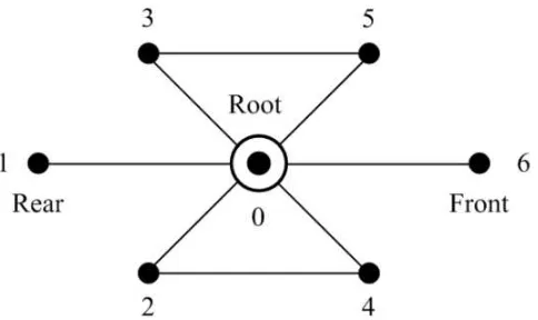
A typical shrimp robot has six wheels. Its structural complexity results in a perception that it is a hard-to-build robot. For straightforwardness, our shrimp rover is represented by a graph shown in Figure 5. It has seven major vertices (v), including the root (v0). Thus, the graph is a rooted type. The respective vertices or the center of rotation is summarized in Table 1. Similarly, all the other vertices are named based on the vertex number seen in Figure 5.
3.2 Theoretical Outline
3.2.1 Graph Representation
Figure 5. A simplified model of shrimp robot that is represented by a rooted graph
Table 1. Designation of vertices for the simplified shrimp mechanism graph Vertex Remark
0 Center of rotation 1 Rear wheel
2 Rear-pair wheel, right 3 Rear-pair wheel, left 4 Front-pair wheel, right
3.2.2 Mechanism Definition and Proposition
Definition 1: Let the wheels be designated by nodes shown in Figure 4. Consequently, the nodes are represented by vertices of a rooted graph shown in Figure 5.
Definition 2: Let the normal forces defined in Eq. 1 be known as the ground reaction forces. The ground reaction forces (GRFs) will be treated within the discrete events
as opposed to the normal forces that are treated within the continuous events.
Definition 3: Let the events that take place while roving be defined by a dynamic model so that all active joints respond accordingly, that the platform maintains at
front-leftrear-fork front-rightabsorber-rear
rear-left
rear-right front-fork absorber-frontF F F F F F
F F M zb
(3)
5 4 3 2 6 1
v v v v v v
F F F F F F ma (4)
Proposition 1: Let the events taken place while roving, the number of possible events may be counted by a combination instantaneous reactions. For the rover, there are 64
possible combinations.
Proof: All joints of every vertex are dynamic, except the root. There exist, at least 64 possible combinations of the instantaneous reaction. There are six active vertices,
where n = 6, because 2n = 64.
Definition 4: An event is designated by a membership function. A membership function () refers to an event by a degree of instantaneous reaction force. This
reference is made by real numbers -4 to 4 where {-4: maximum low}, whereas {4:
maximum high}.
Proposition 2: The events that take place while roving will have induced certain degrees of reactions where Eq. 5 defines the rover behavior based on sequences
1, 64 3 2 1
, , , 0 null
1 2 3 4
i j v
f
Q N N f f h
f
H F (5)
Proof: Suppose that the rover will roam over a rugged terrain. Therefore, all wheels will be subjected to a certain amount of GRFs such as depicted in Figure 1, and is
explained in Eq. (1). These reactions will have some degrees of forces depending on
the ground contour and the rover’s instantaneous speed. Using this premise, the
reactions are discretized based on the degrees they reacted at that instance. So that,
Eq. (5) defines that for every sequence (Q) that the rover makes, there are certain
degrees of GRFs act on each wheel. A degree value (4) is a ceiling value obtained
from the product of GRF and gain, whereas (-4), a floor value. These are the
thresholds. The extrema are the results of the peaks and valleys of a ground contour.
3.3 Design of the Mobile Platform
It has with two forks, at front and rear, respectively. The forks have extra suspensions, whereas the platform relies on the suspension given by the wheels. The material used was mostly of aluminum alloy of grade AL-6063-T5, chosen for its durability, weight, and ease of installation.
![Figure 1. InsBot (adapted from [9])](https://thumb-ap.123doks.com/thumbv2/123dok/532595.61675/15.595.148.451.71.245/figure-insbot-adapted-from.webp)
![Figure 2. Prototype of the LIPCA robot (adapted from [10])](https://thumb-ap.123doks.com/thumbv2/123dok/532595.61675/16.595.191.409.560.679/figure-prototype-lipca-robot-adapted.webp)