DESIGN OF X BAND MIXER FOR MICROWAVE COMMUNICATION
SITI SAHHIADA ASHIKIN BINTI MOHD YASIM
This Report Is Submitted In Partial Fulfillment Of Requirements For The Bachelor Degree of Electronic Engineering (Wireless Communication)
Faculty of Electronics and Computer Engineering Universiti Teknikal Malaysia Melaka
ii
UNIVERSTI TEKNIKAL MALAYSIA MELAKA
FAKULTI KEJURUTERAAN ELEKTRONIK DAN KEJURUTERAAN KOMPUTER
BORANG PENGESAHAN STATUS LAPORAN
PROJEK SARJANA MUDA II
Tajuk Projek : DESIGN OF X BAND MIXER FOR MICROWAVE COMMUNICATION
Sesi
Pengajian : 1 1 / 1 2
Saya………..SITI SAHHIADA ASHIKIN BINTI MOHD YASIM………. mengaku membenarkan Laporan Projek Sarjana Muda ini disimpan di Perpustakaan dengan syarat-syarat kegunaan seperti berikut:
1. Laporan adalah hakmilik Universiti Teknikal Malaysia Melaka.
2. Perpustakaan dibenarkan membuat salinan untuk tujuan pengajian sahaja.
3. Perpustakaan dibenarkan membuat salinan laporan ini sebagai bahan pertukaran antara institusi pengajian tinggi.
4. Sila tandakan ( √ ) :
SULIT*
*(Mengandungi maklumat yang berdarjah keselamatan atau kepentingan Malaysia seperti yang termaktub di dalam AKTA RAHSIA RASMI 1972)
TERHAD** **(Mengandungi maklumat terhad yang telah ditentukan oleh organisasi/badan di mana penyelidikan dijalankan)
TIDAK TERHAD
Disahkan oleh:
__________________________ ___________________________________
(TANDATANGAN PENULIS) (COP DAN TANDATANGAN PENYELIA)
iii
“I hereby declare that this report entitles Design of X band mixer for microwave communication is result of my own work except as cited clearly in the references.”
Signature : ... Student : SITI SAHHIADA ASHIKIN
iv
“I hereby declare that I have read this report and in my opinion this report is sufficient in term of the scope and quality for the award of the Bachelor Degree of Electronic
Engineering (Wireless Communication) ”
Signature :………...
Supervisor Name : 1)Mr. Abd Shukur bin Jaa’far
Date :………...
Signature :………...
Supervisor Name :2) Mr. Azlishah bin Othman
v
Specially dedicated to
vi
ACKNOWLEDGEMENT
vii
ABSTRACT
This project is about designing a X band mixer for RF communication. X band is the frequency spectrum which has range from 8 GHz until 12 GHz. The mixer is required to operates at 10 GHz . The basic function of mixer that need to understands is perform the sum and a difference frequency at a single output port when two distinct input frequencies are inserted into the other two ports. For transistor selection, FET is be decided because of its features compare with BJT. There are many types of mixer which are as their own characteristic performance. For this project, active mixer is choose as the first step in designing this mixer. The other theories and method that explore in this project is about the calculation how to get the value of resistance and the smith chart utility to get the value of the capacitor and inductor besides determined the types of DC biasing that will be used during designing this mixer. Based on the finding simulation result, it shows that active mixer and the transistor used be able to be used in this designing even though from the studying on journal, almost of them used Gilbert Cell mixer that can perform at high frequency.
viii
ABSTRAK
ix
TABLE OF CONTENT
CHAPTER TITLE PAGE
PROJECT TITLE i
REPORT STATUS FORM ii
DECLARATION iii
DEDICATION v
ACKOWLEDGEMENT vi
ABSTRACT vii
ABSTRAK viii
TABLE OF CONTENT ix
LIST OF TABLE xii
LIST OF FIGURE xiii
LIST OF ABBREVIATIONS xv
ABSTRACT 1
I INTRODUCTION 3
1.1 Project overview 3
x
1.3 Problem Statement 5
1.4 Scope of Project 6
1.5 Methodology 7
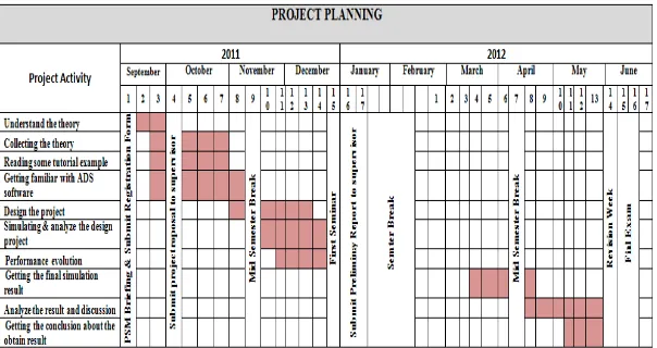
1.6 Work Schedule 9
II LITERATURE REVIEW 10
2.1 Active Mixer 6
2.2 Down Conversion 8
2.3 Up Conversion 9
2.4 Biasing 11
2.5 Designing Software 14
2.6 Mixer Analysis 18
2.6.1 Conversion Loss 19
2.6.2 Isolation 19
2.6.3 Noise Figure 19
2.6.4 Conversion Compression 20
2.6.5 Dynamic Range 20
2.6.6 Intercept Point 21
III PROJECT METHODOLOGY 23
3.1 Flowchart of Implantation Planning 23 3.2 Methodology in Designing X Band Mixer 26
IV RESULT AND ANALYSIS 27
4.1 FET Curve Tracer 27
xi
4.3 S - Parameter
4.3.1 S – Parameter Before Matching 31 4.3.1 Smith Chart 33 4.4 Input and Output Matching Impedance
4.4.1 Pi Network Impedance Matching 37 4.4.2 Transformer Network Impedance Matching 38 4.4.3 Lumped Network Impedance Matching 39 4.5 Result analysis for S- Parameter 40
4.6 Harmonic Balance 43
4.7 Input Intercept Point ( IIP3) 45
V CONCLUSION AND RECOMMENDATION 46
5.1 Conclusion 46
5.2 Future Work 48
REFERENCES 49
xii
LIST OF TABLES
NUMBER DESCRIPTION PAGE
xiii
LIST OF FIGURES
NUMBER DESCRIPTION PAGE
1.1 Down converting mixer model 4
1.2 Basic of RF block 5
1.3 Scope of work 6
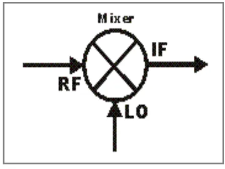
2.1 Schematic symbol for a mixer 11
2.2 Definition of down and up conversion 11
2.3 ATF – 36163 transistor 12
2.4 Down conversion system 14
2.5 Up conversion system 14
2.6 Basic figure of voltage divider configuration 15 2.7 Circuit for voltage bias calculation 15
2.8 Q-point for voltage divider 16
2.9 ADS software 18
2.10 Intercept point 21
3.1 Flowchart of overall planning 24 3.2 Methodology in designing X band mixer 26
4.1 Circuit for FET curve tracer 27
4.2 Result for FET curve tracer 28
4.3 DC biasing analysis circuit using FET voltage divider 29
xiv
4.5 S parameter circuit before matching 31 4.6 Simulation graph for unmatching circuit 32
4.7 Smith chart before matching 32
4.8 Impedance value of �11 and �22 33
4.9 Smith chart from ADS simulation 34
4.10 Manual plotting smith chart 35
4.11 Circuit S parameter after matching 36
4.12 Input and output matching network 36
4.13 Pi -network topology 37
4.14 T- network topology 38
4.15 L- network topology 39
4.16 Two-port network 40
4.17 Graph for�11 41
4.18 Graph for �12 42
4.19 Graph for �21 42
xv
LIST OF ABBREVIATIONS
RF - Radio Frequency IF - Intermediate frequency
LO - Local oscillator
ADS - Advanced design system S Parameter - Scatterring parameter FET - Field effect transistor BJT - Bipolar junction transistor LNA - Low noise amplifier
dB - Decibel
IIP - Input intercept point OIP - output intercept point
DC - Direct current
L network - Lumped network T network - Transformer network
1
ABSTRACT
Now a days, a number of communication technologies are increased. The high performance of the technologies is very important to perform the process of transmit and receive the signal. Amplifier, frequency converter (mixer and oscillator) and filter are the basic function blocks in RF system Mixer is a transceiver component that can transmit and receive signal. It will combine two or more signal into one composite signal and operates in any frequency depend on requirement. X band is a one electromagnetic spectrum which operates at 8GHz until 12 GHz. This project is about designing of X band mixer for microwave communication.
Microwave communication is communication via radio using the antenna tower and also knows as line of sight (LOS). The gain and the conversion for this
communication is very important in order to get the exact signal as we have
transmitted. The purpose of this project is to design the mixer that because the higher bandwidth will allow to transmit more data.
The objectives of this project is to perform a simulation that fall at desired frequency which is 10 GHz. By exploring the journal about the mixer and about the for
software, the simulation is as expected. To complete this project have four stages of methodology.
The first stage is literature review which need student to do some research about the theory based on the project title. To complete the literature review, student can refer from internet, journals, books and articles.
2
System 2011) and third is characterization and experimentation. In this stage, student will analyze the DC analysis and RF analysis. The last stage is thesis writing and report. This thesis will include overall of the project flow until the getting the desired result as expected.
3
CHAPTER 1
INTODUCTION
1.1 Project overview
This project is to design a X band mixer for radio frequency (RF) communication. The X band is a segment of the microwave radio region of the electromagnetic spectrum. In some cases, such as in communication engineering, the frequency range of X band is rather 7.0 to 11.2 gigahertz (GHz). In radar engineering, the frequency range is specified by the IEEE at 8.0 GHz to 12.0 GHz. For this project, the mixer required to operates at 10 GHz.
RF Mixer are 3 port-active or passive devices. They are designed to yield both, a sum and a difference frequency at a single output port when two distinct input frequencies are inserted into the other two ports. Microwave mixer is usually based on the
4
Figure 1.1 : Down converting mixer model
Equation 1.1.1
Where A and B is constant
5
Figure 1.2 : Basic of RF Block
1.2 Objective Of The Project
1.2.1 To study the X band mixer which operates at 10 GHz
1.2.2 To study the ADS software in order to get the design for X band
1.2.3 To design X band mixer using ADS for microwave communication .
1.3 Problem Statement
Mixer is a design to sum or difference frequency at single output when two
distinct input frequencies are inserted into the two port X band mixer if one of most highest frequency that can operates by RF communication .The higher frequency will speed up the sending of data transmission.
6
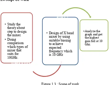
• Study the theory about step to design the mixer. • Doing
comparison which types of mixer that suits for 10GHz.
PART 1 STUDY ON THEORY
• Design of X band mixer by using suitable biasing to achieve expected
frequency which is 10 GHz
PART 2 SIMULATION
•Analyze the graph and get the highest gain fall at 10 Ghz.
PART 3 ANALYZE
need to choose the suitable biasing for the types of mixer chosen. Calculation need to be careful so that the value that will obtained in software is right.
1.4 Scope Of Work
Figure 1.3 : Scope of work
There are three scope of work in order to complete the simulation of this project. The first part is study on theory. This part is important in order to explore how the mixer works and the step to design the mixer because there are many types of mixer have in this communication. We also need to choose which type of mixer that will be used as our design to for this project.
The second part is simulation part . In this part, the ADS software is used to design the mixer. The biasing of mixer based on the type of mixer that we choose. Before starting with the simulation, the calculation for the biasing must be completed first.
7
1.5 Methodology
For methodogy, this project involves 4 major stages:
1 st phase: Literature Review
Collectiong the project‟s information from text book, Internet, journals and reference books
Doing research to know more detail about designing the X band mixer for microwave communication
Famaliarize with ADS software Have discussion with supervisor
2nd phase: Design and simulation
Analyzed and calculated all the parameters that related to design
Construct the X band mixer by using the ADS software and the parameter
3rd phase: Characterize and experimentation
DC Analysis
The purpose of DC analysis is to establish the appropiate bias condition for the device area or width that needed in the mixer
DC analysis is very useful because it will clarifies the range of operating conditions possible without cause into the ohmic or cut of regions
RF Analysis
RF analysis is important to avoid leakage effect, complicating the design of the complete system.
8
4th phase: Thesis writing or report writing
9
1.6 Work Schedule