Design Considerations of MEMS Based
Piezoelectric Cantilever for Harvesting Energy
*Swee-Leong, Kok,
MIEEE,**Ab Rahman, Mohd Fauzi
*Faculty of Electronic and Computer Engineering, **Faculty of Engineering Technology Universiti Teknikal Malaysia Melaka,
Hang Tuah Jaya, 76100 Durian Tunggal, Melaka, Malaysia *
Abstract— One of the challenges of miniature electronic system such as those work as a part of a wider wireless sensor system is to provide sustainable electrical power source to all the electronic components in a small enclosure of sensor node. However, as the size of the micro-power generator reduces, the physical limitations as well as the reduction of output power become the major concerns of the usefulness of a miniature energy harvester. In this paper, the design is taking into considerations of the mechanical as well as the electrical properties of an unimorph piezoelectric cantilever. These encompassed the natural frequency and the neutral axis of the structure. Resistive load was also being investigated for optimizing the electrical output power of the micro-generator. It was found that the issue of the maximum deflection of the cantilever is more prominent than the stress on the cantilever for a miniature device. The adjustment on the neutral axis as well as on matching with resistive load are also important in generating optimum electrical output power.
Keywords— PowerMEMs, Lead Zirconate Titanate (PZT), Energy harvesting, Unimorph cantilever
I. INTRODUCTION
Making the reality of ambient vibration energy harvesting using MEMS based micro-power generator or PowerMEMS is very challenging. Some of the challenges include fabricating a robust MEMS structure, ensuring the structure resonates with the vibration sources, solving the problem of unpredictable ambient vibrations [1] and meeting the minimum electrical energy requirement.
It is critical to optimise the performance of the energy harvester in order to produce useful electrical energy for powering microsystem. An open circuit output voltage is an important indicator to determine the practical usage of the device. For most of the electronic applications, usually the AC voltages generated by a micro-generator are converted to usable DC voltage. In this conversion, diodes are normally used for simple full wave direct rectification, which need a minimum forward voltage of 300 mV for each diode to operate. The minimum voltage was able to be reduced to 150 mV by replacing the diodes with active switches in a four stages voltage multiplier circuit as studied by Saha et al [2]. A few tens of micro-watts of electrical power are needed for powering ultra low-power electronics, MEMS sensors and RF communications system. As reported by Torah et al [3], 58
W of power is needed to power an accelerometer based micro-system.
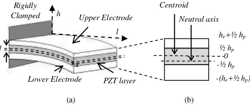
In this paper, a thick-film piezoelectric unimorph cantilever structure [4] is modelled. An active piezoelectric layer is sandwiched in between upper and lower electrodes as
shown in Fig. 1. The design features and dimensions of the MEMS micro-power generator is based on the constraints imposed by the fabrication technology (in this case, thick-film technology) [5] and the physical constrains of the real device (e.g. the maximum allowed displacement and stress before the device fails to respond accordingly or is broken) in order to fabricate a robust MEMS structure.
II. THE DESIGN CONSIDERATIONS
The smaller the feature size of the energy harvester the better it is for miniature system integration. However, the output electrical energy reduces as the size of the generator decreases. Therefore an optimum design is needed to trade-off between the electrical energy output and the compactness of the device.
Fig. 1: A unimorph cantilever structure with cross-sectional view.
Generally, the base excited harmonic motion is modelled as a spring-mass-damper system (k, M, b) with the equation of motion [6],
(1)
where y denotes the displacement of the base and x the displacement of the mass from its static equilibrium position.
By defining the relative displacement z = x – y and y(t) = Y sin ωt, the magnitude of the displacement and acceleration can be derived as,
(2a)
0bx y x y x
M
Y
r r
r Z
2 2
2 2
2
1
l h
d
Neutral axis Centroid Upper Electrode
Lower Electrode PZT layer Rigidly
Clamped
he+½ hp
-(he+½ hp)
½ hp
-½ hp
0
(2b)
where r is the frequency ratio of excited and natural frequency
of the structure ω/ωn and ζ is the damping ratio equal to damping coefficient divided by the factor of 2M ωn.
(1) Natural Frequency of a Unimorph Cantilever
From the Bernoulli-Euler equation derivation, a thin cantilever beam with one end clamped and the other end free, the natural transverse vibration can be written as,
(5)
where vi is the coefficient of oscillation mode, mw is the mass per unit area for the unimorph cantilever with thickness, h and density , for piezoelectric layer, with subscript p and electrode layer, e is given as,
(6)
D in equation (5) is the bending modulus per unit width, which is given by [91],
(7)
where ei is the elastic modulus for the particular layer (ee denotes elastic modulus for electrode layer and ep denotes elastic modulus for piezoelectric layer), h is the thickness of a particular layer of the structure and hN is the neutral axis from
the reference point, “0”. For simplification to estimate the natural frequency of a symmetrical unimorph cantilever, the neutral axis is assumed to be coincident with the centroid of the PZT layer. Therefore, the bending modulus per unit width for the unimorph structure is,
(8)
The first mode natural frequency of the unimorph structure can be calculated by substituting equations (6) and (8) into (5),
(9)
(2) Location of Neutral Axis of a Unimorph Cantilever
A bending beam is subjected to tension and compression proportional to the distance above and below the neutral axis respectively as shown in Fig. 1(b). There is no resultant force acting on the cross section at the neutral axis and the stress, σx is the multiplication of elastic modulus, e, curvature, κ and the distance from the neutral axis, y. Since E and κ are nonzero, therefore,
(10)
The distance from the centroid of PZT layer to the neutral axis is therefore,
(11)
We can see from equation (11), if the thickness of the upper electrode is similar to the lower electrode, he1 = he2, the neutral axis is located at the centre of the PZT layer, therefore, d = 0. This will give a zero resultant stress, hence zero stress.
(3) Maximum Allowed Stress
The resultant stress on the clamped area of a beam for each layer of a unimorph is proportional to the input moment divided by the inertia across the length of the beam as,
(12)
If the neutral axis is at the PZT centroid, hN = ½ hp and the upper electrode and lower electrode are made of same material and with same thickness, he the moment of inertia of the unimorph can be simplified as,
(13)
Therefore the resultant stress can be derived from equation (12) and (13) as,
(14)
The resultant stress is proportional to the distance from the neutral axis, and therefore the thicknesses of the upper and lower electrodes are very critical in determining the resultant stress of the beam.
(4) Maximum Allowed Deflection
The factor that limits the deflection of the cantilever is the height of the tip of the cantilever to the base of the device. The maximum deflection of the cantilever has to be known so that the maximum dimension of the cantilever can be designed to suit the fabrication process. The deflection, z of a cantilever beam can be described by differential equation of the deflection curve as [7],
Y r rZ
2 2 2 2 1 1 w b i i m D l v f 2 2 2
h h
dhe D n i N i
1 2 e e p pw
h
h
m
2
3 3 2 2
2 3 4 3 3 2 12 1 e p e p e e p p
unimorph e h e h h h h h D e e p p e p e p e e p p b N h h h h h h h e h e l f 2 2 3 4 3 8 1615 . 0 2 2 3 3 2 0
A AA
dA e
hdA hdA
2 1
1 2 2 2 1 2 2 2 2 1 e e ep p e p e e ep p p h h n h h h h h n h h d
2 2 2 2 1 2 2 1 1 1 236 . 0 118 . 0 r r D y l w M h h h d l e unimorph b b pm p p e e e b p l dl I d l M l b l unimorph bl
0) ( 1
p ep e p e e p
unimorph w h n h h h h h
I 3 3 2 2
(15)
where eT is the resultant elastic modulus of PZT and electrode layers. Solving equation (15), with the substitution of equation (4) and (13) the deflection of the cantilever can be derived as in equation (16).
(16)
(5) Estimated Output Voltage
The mass-spring-damper system can be used to estimate the output voltage of a piezoelectric cantilever. The analogous of the electrical domain of the system is shown in Fig. 2 [8]. It was first described by Williams and Yates [9], there is a similar model developed by Roundy [10].
Fig. 2: A diagram of an analogous circuit for a piezoelectric vibrated device with a resistive load.
The mechanical domain of the equivalent circuit consists of inductor, resistor and capacitor which represents the mass of the generator, M, the mechanical damping, bm, and mechanical stiffness, eT respectively. At the electrical domain, Cp is the capacitance of the piezoelectric and R is the external resistive load, while n is the equivalent turn ratio of the transformer which is proportional to the piezoelectric charge constant d31. V is the voltage across the piezoelectric and i is the current flow into the circuit, which are analogues to the stress and the strain rate respectively. The output voltage at resonant frequency derived from the model is,
(17)
where j is the imaginary number, r is the fundamental resonant frequency of the cantilever, eT is the elastic constant for the composite structure (N/m2), d31 is the piezoelectric
charge coefficient (C/N), hP is the thickness of the piezoelectric material, is the dielectric constant of the piezoelectric material (F), T is the total damping ratio, k31 is the piezoelectric coupling factor, CP is the capacitance of the piezoelectric material, R is the resistive load, and d is the distance from the centroid of the layer of PZT to the neutral axis of the structure. The rms value of power transferred to the resistive load can be written as,
(18)
III.ANALYSIS AND DISCUSSION ON CALCULATION RESULTS
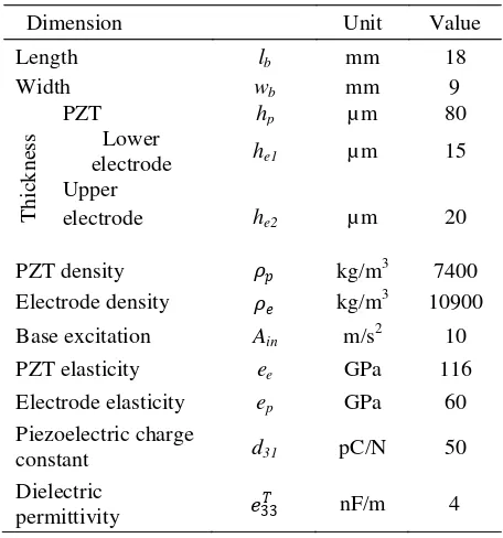
The calculation takes into account of the effect of cantilever length on the mechanical damping, coupling factor and matching resistive load. These parameters were measured experimentally and were used to fit in the model. Table 1 shows the standard parameters being used in the calculation.
Fig. 3 and 4 show the dependence of maximum stress and deflection respectively on the cantilever length. Two conditions of mechanical damping ratio are compared in the calculation. One is calculated with experimental damping value and the other one is calculated with fixed value of 0.0037. If the experimental value of 115 MPa is taken as the upper limit of the maximum stress allowed, theoretically the cantilever can have a length up to 850 mm before it breaks, with the assumption that the damping ratio increases proportionally with length. For a damping ratio fixed at 0.003, however, the maximum allowed length of the cantilever is 148 mm.
Table 1: Standard dimensions of a cantilever used to verify theoretical model.
Dimension Unit Value
Length lb mm 18
Width wb mm 9
T
h
ick
n
ess
PZT hp µm 80
Lower
electrode he1 µm 15
Upper
electrode he2 µm 20
PZT density �� kg/m3 7400
Electrode density �� kg/m3 10900
Base excitation Ain m/s2 10
PZT elasticity ee GPa 116
Electrode elasticity ep GPa 60
Piezoelectric charge
constant d31 pC/N 50
Dielectric
permittivity �33� nF/m 4
unimorph TI e
l M dl
z
d ()
2 2
2 2
2
2 1 2 1 4
2 1
1 1
1 1
3
236 . 0 236
. 0
r r
D h h h
h n
y l w M h
h h l
z
unimorph p
e e
p ep
b b p
p e e e b
p r T r
r T b
in p T
RC k
j l
da h d je V
2 4
3
2 31 2 2
2
31
2
231 2
4 31 2
2 2 31 2
2
4 4
4 1
T r P T r P T
in P t P
r k RC k RC
a B h d e RC P
In the case of limitation on gap height at 2 mm for a miniature micro-power generator, the allowed length of the cantilever is about 25 mm, for the assumption case, however a shorter cantilever is allowed at 23 mm if the damping ratio is fixed at 0.0037. These calculation results show that, a slight change of mechanical damping ratio can lead to a large change of stress and displacement of a free-standing structure, therefore an accurate experimental damping ratio value is important in determining the length of the structure to meet the operation restrictions. From the assumption that the damping ratio increases proportionally with length, the maximum allowed cantilever length is 25 mm for a base excitation at 10 m/s2.
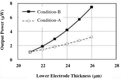
According to equation (17), the output voltage increases proportionally to the distance, d, as can be seen from Fig. 5, where condition-A is by fixing the thickness of upper electrode while varying the thickness of lower electrode. Condition-B is fixing the total thickness of the unimorph cantilever. It shows that the changing rate of output voltage is greater for condition-B compared to condition-A, which becomes significant at higher electrode thickness differences between upper and lower electrodes. There is an improvement of output power for condition-B by a factor of 7 when an adjustment was made to the thickness of the lower electrode from 21 µm to 26 µm while maintaining the total thickness of the electrodes at 36 µm.
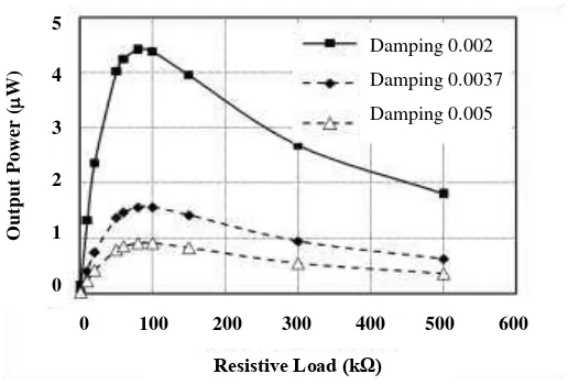
The output voltage and power of the device is also dependent on the external resistive load connected to the piezoelectric terminal. The estimated open circuit voltage is 960 mV for a cantilever with damping ratio of 0.002 when excited to its resonant frequency at an acceleration level of 10 m/s2, as shown in Fig. 6. An optimum output power of 4.5 µW is generated when it is driving an external resistive load
of 80 kΩ, as shown in Fig. 7. A few scenarios with different mechanical damping ratios for the same device were calculated to estimate the electrical output. These show that the lower the damping ratio the better the performance of the energy harvester. However, the mechanical damping is an inherent property of the cantilever structure which is very difficult to control.
IV.CONCLUSION
The physical constraints related to maximum stress and deflection are important factors in designing a miniature micro-power generator for harvesting energy from ambient environment. The minimum electrical power requirement for low power electronic applications is also a major concern in designing the devices. The power output from the micro-generator can be improved by adjusting the neutral axis away from the centroid of the unimorph cantilever structure, whereby maximum stress is induced in the unimorph piezoelectric layer, hence more electrical charges are generated. Further increment of output power can be obtained by matching the piezoelectric cantilever with optimum external resistive load.
Fig. 3: Theoretical calculation of cantilever length variation effect on maximum stress for two cases; one with damping fixed at 0.0037 and the other one is the value measured from experiment.
Fig. 4: Theoretical calculation of cantilever length variation effect on maximum deflection for two cases; one with damping fixed at 0.0037 and the other one is the value measured from experiment.
Fig. 5: Theoretical calculation of the condition-A (constant upper electrode) and –B (constant total thickness) effect on output power.
M
a
x
imu
m
S
tr
e
ss (M
P
a
)
Cantilever Length (mm)
Ma
x
im
u
m
S
tr
ess
(
MPa
)
Cantilever Length (mm) 1000
100
10
1
0.1
0.01
1 10 100 1000
Experimental Damping Damping fixed at 0.0037
20 22 24 26 28
O
u
tp
u
t
Po
we
r
(
W)
Lower Electrode Thickness (m) 8
6
4
2
0
Condition-B Condition-A
M
a
x
im
u
m
De
flec
tio
n
(
m)
Cantilever Length (mm) 800
600
400
200
0
0 5 10 15 20
Fig. 6: Theoretical calculation of the electrical output voltage as a function of electrical resistive load for three different damping factors.
Fig. 7: Theoretical calculation of the electrical output power as a function of electrical resistive load for three different damping factors.
ACKNOWLEDGMENT
The authors would like to acknowledge the support of this work by the Faculty of Electronic and Computer Engineering, Universiti Teknikal Malaysia Melaka (UTeM) to present this paper in the conference.
REFERENCES
[1] Miller, L.M., Halvorsen, E., Dong, T., and Wright, P.K. “Modeling and experimental verification of low-frequency MEMS energy harvesting from ambient vibrations. Journal of Micromechanics and Microengineering, 2011, 21, p.045029.
[2] Saha, C., O'Donnell, T., Godsell, J., Carlioz, L., Wang, N., McCloskey, P., Beeby, S., J. Tudor, and R. Torah. “Step-up converter for electromagnetic vibration energy scavenger”. in DTIP of MEMS & MEOMS. 2007. Stresa, Italy, April.
[3] Torah, R., Glynne-Jones, P., Tudor, M., O'Donnell, T., S. Roy, and S. Beeby, Self-powered autonomous wireless sensor node using vibration energy harvesting. Measurement Science and Technology, 2008.
19(12): p. 125202.
[4] Kok, S.L, White, N.M, and Harris. “Free-standing thick-film
piezoelectric multimorph cantilevers for energy harvesting,” in IEEE International Ultrasonics Symposium (IUS) 2009, 20 – 23 September 2009, Roma, Italy.
[5] Kok, S.L, White, N.M, and Harris, N.R. “A free-standing, thick-film
piezoelectric energy harvester,” in IEEE sensors 2008, 26 – 29 October 2008, Lecce, Italy.
[6] Rao, S.S., Mechanical vibrations. 2004: Pearson Prentice Hall. [7] Gere, J.M., Mechanics of Materials. 2001: Brooks/Cole.
[8] Liang, J., and Liao, W. “Impedance modeling and analysis for
piezoelectric energy harvesting systems,” IEEE/ASME Transactions on Mechatronics, 2011, 99, pp. 1-13.
[9] Williams, C.B. and Yates, R.B. “Analysis of a micro-electric generator for microsystems,” Transducers 95/Eurosensors IX, 1995: p. 369-372. [10] Roundy, S., and Wright, P.K. “A piezoelectric vibration based
generator for wireless electronics,” Smart Mater. Struct. 2004, 13, pg. 1131-1142.
O
u
tp
u
t
Vo
lt
a
g
e
(
mV
)
Resistive Load (kΩ)
1000
800
600
400
200
0
0 100 200 300 400 500 600
Damping 0.002 Damping 0.0037 Damping 0.005
5
4
3
2
1
0
0 100 200 300 400 500 600
O
u
tp
u
t
Po
we
r
(
W)
Resistive Load (kΩ)