UNIVERSITI TEKNIKAL MALAYSIA MELAKA
AN ACCURACY STUDY ON THE POSITIONING OF THE PICK
AND PLACE MANIPULATOR TRAINER
This report submitted in accordance with the requirements of the Universiti Teknikal Malaysia Melaka (UTeM) for the Bachelor Degree of Manufacturing Engineering
(Robotic and Automation) with Honours.
By
DENIS CHUA KIANG WUI
i
ABSTRACT
This project is a further study to improve the pick and place manipulator trainer to be more accurate on positioning through identifying the problems that had occur on the previous manipulator project. Through the literature review, some idea on the particular part which requires improving are studied. Then, the study on existing hardware is done by identifying problem using calculation and graphical review. The critical parts involved are gripper, rotary table, and dual rod cylinder. In order to overcome the limitation of positioning, the control system is improved by changing and adding the feed back component’s signal to the pneumatic actuator such as sensor, reed switch, and directional valve. On the other hand, the OMRON CPM 2A controller will be use to replace the Keyence KV- 16T. Through this project, theoretical knowledge and practical skill is applied into this manipulator. This project provides a further understanding on software coding and hardware usage.
ii
ABSTRAK
iii
DEDICATION
iv
ACKNOWLEDGEMENT
v
List of Abbreviations, Symbols and Nomenclature xiv
1. INTRODUCTION 1
1.1 Background 1
1.2 Objective 2
1.3 Scope 2
1.4 Problem Statement 3
2. LITERATURE REVIEW 4
2.1 Introduction to Control Design 4
2.1.1 Term for Using in the Control Design 7
2.1.1.1Transient Response 7
2.1.1.2Steady-State Response 7
2.1.1.3Steady-State Error 8
vi
2.2 Pneumatic Actuating System 9
2.3 Programmable Logic Controller 14
2.4 Sensor 17
2.4.1 Absolute Rotary Encoder 19
2.4.2 Standard Binary Encoding 20
2.4.3 Optical Encoder 22
3.1.1.3Dual Rod Cylinder 29
3.1.2 Modification 29
3.2.4 Laser Cutting Machine 32
4. ANALYSIS ON EXISTING HARDWARE 33
4.1 Existing Hardware Study 33
4.1.1 Calculation on Gripper MHZ2 – 10D 34
4.1.2 Calculation on Rotary Table MSQB – 10A 35
4.1.3 Calculation on Dual Rod Cylinder CXSM 10 – 75 40
vii
4.3 Existing Software Study 42
4.4 Conclusion on Analysis Existing Software 44
5. DESIGN AND DEVELOPMENT 45
5.1 Sensor Comparison for Dual Rod Cylinder and Gripper 45
5.2 Sensor Comparison for Rotary Table 47
5.3 Mechanical Design 48
5.3.1 Encoder Disc 48
5.3.2 Sensor Bracket 49
5.3.3 Directional Control Valve Bracket 50
5.4 Electrical Design 51
5.4.1 Hard Wiring 51
5.4.2 Control Wiring 52
5.4.2.1 Relay Wiring 52
5.4.2.2 PLC Input Wiring 54
5.4.2.3 PLC Output Wiring 56
5.5 Program Design 58
viii
6 DISCUSSION 64
6.1 Programming Discussion 64
6.2 Result Discussion 72
7 CONCLUSION AND SUGGESTION 73
7.1 Conclusion 73
7.2 Suggestion 74
REFERENCES 75
APPENDICES
APPENDIX A MECHANICAL DESIGN APPENDIX B ELECTRICAL DESIGN
APPENDIX C PROGRAMMING ALOGARITHM APPENDIX D ENCODER MACHINING LANGUAGE APPENDIX E DATA SHEET FOR SENSORS
APPENDIX F DATA SHEET FOR SOLENOID VALVE
ix
LIST OF FIGURES
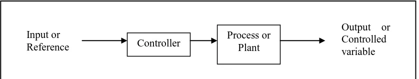
Figure 2.1 Open Loop Control System 5
Figure 2.2 Close Loop Control System 6
Figure 2.3 Transient Response 7
Figure 2.4 Diagram of The Rotary Pneumatic Manipulator 12 Figure 2.5 Diagram of The Linear Pneumatic Manipulator 13
Figure 2.6 Block Diagram of PLC 15
Figure 2.7 The Sensing Process 17
Figure 2.8 Absolute Rotary Encoder 19
Figure 2.9 Rotary encoder for angle-measuring devices marked in
3-bit binary 20
Figure 2.10 Optical Interrupter 22
Figure 2.11 Optical Encoder 22
Figure 2.12 The Output Signal in Digital Wave Form 22
Figure 2.13 The circuit of the disc encoder 23
Figure 2.14 Photoelectric Sensor 25
Figure 3.1 Flow Chart of Methodology Process 28
x
Figure 4.1 Existing Hardware 33
Figure 4.2 Gripper Force 35
Figure 4.3 Dimension of Dual Rod Cylinder 36
Figure 4.4 Dimension to Center of Rotary Table 36
Figure 4.5 Inertia load 38
Figure 4.6 The Force VS Operation Pressure During Out and In Operation 41
Figure 4.7 Existing PLC Ladder Diagram 42
Figure 5.0 Internal Circuit of D-Z73 47
Figure 5.1 Internal Circuit of D-Y58A 47
Figure 5.2 Encoder Disc 48
Figure 5.3 Sensor Bracket 49
Figure 5.4 Directional Control Valve Bracket 50
Figure 5.5 Hard Wiring 51
Figure 5.6 Relay wiring 52
Figure 5.7 PLC Input Wiring 54
Figure 5.8 PLC Output Wiring 56
xi
Figure 6.0 Project Workspace Window 65
Figure 6.1 PLC Settings Window 65
Figure 6.2 Initial Condition 65
Figure 6.3 Special Condition 66
Figure 6.4 Shift Instruction (SFT) for Manual Function 67 Figure 6.5 Shift Register (SFT) for Homing Function 69 Figure 6.6 High Speed Counter PV Read (PRV) Instruction 70
Figure 6.7 Compare Instruction 70
Figure 6.8 Great Than Flag 70
Figure 6.9 High Speed Counter Reset 71
xii
LIST OF TABLES
Table 2.1 Classification of Sensor 18
Table 2.2 Standard Binary Encoding 21
Table 2.3 The selection Model of Reed Switch for Cylinder CXSM10 – 75 24
Table 4.1 Air Consumption of Rotary Table 40
Table 4.2 Force of The Dual Rod Cylinder 41
Table 4.3 List of Input 43
Table 4.4 List of Output 43
Table 5.0 Sensor Comparison for Dual Rod Cylinder and Gripper 46
Table 5.1 Sensor Comparison for Rotary Table 47
Table 5.2 List of Relay wiring 53
Table 5.3 List of Input 55
Table 5.4 List of Output 57
Table 5.5 Time Motion Diagram 62
Table 5.6 Signal Input Diagram 63
xiii
xiv
LIST OF ABBREVIATIONS, SYMBOLS AND
NOMENCLATURE
CNC - Computer Numerical Control PLC - Programmable Logic Controller
a - Safety Margin ƒ - Force
xv
µ - Coefficient of Friction
1
CHAPTER 1
INTRODUCTION
1.1Background
Nowadays, robots play an important role in industry. They can replace human labor in highly hazardous situations, especially in the processes of nuclear clean-up, dismantling and decontamination (Caldwell, 1999). In the industry field, robot manipulator arm is a most common industrial robot to perform the pick-and-place operation. Industrial robots have used three primary actuator types: electric motors (DC or AC), hydraulic cylinders and pneumatic cylinders (Caldwell, 1989). Mostly, the controlled motion was done using electric motors and computers due to powerful if compare with other forms of actuation have become practical for providing motion. But in term of cost, there is not economical and need more experience in programming.
2
A hierarchical close loop feedback control for pneumatic manipulators is proposed to overcome this type of problem. Where the flow of the actuator is controled for velocity, speed, and air consumption. An electrical signal to the controller is conduct as a feed back to the close loop system for read the positioning of the manipulator.
1.2 Objective
The purpose of this project is to have an accuracy study on the positioning of the pick and place manipulator trainer. Thus, the following are the objectives of this project:
a) To identify the specification and function of the existing hardware. b) To understand the sequence of the manipulator trainer.
c) To analyse the correct position for each motion.
d) To ensure the programming in order to control the manipulator trainer.
1.3 Scope
The scope of this invention cum study will be covering the following:
a) Analysis the existing and improve hardware by come out result in graphical form. b) Redesign and apply the suitable electrical circuit.
c) Select suitable component and device.
3 1.4 Problem Statements
Through the observation and testing for the existing manipulator trainer, there were some problems and limitations as below:
a) Manipulator just can run for one cycle only.
b) All of the input signals are using mechanical type sensor with mechanical part for sensing the path.
c) The accuracy, repeatability, and stability are out of effectiveness because using the mechanical part to fix the limit of manipulator path.
d) The position of the manipulator cannot reset for homing when is needed.
e) When the OFF button is press emergency, the manipulator still in running condition. f) Once the ON and OFF button is press equally, still can operate the manipulator is
4
CHAPTER 2
LITERATURE REVIEW
2.1 Introduction to Control Design
Robot is a re-programmable, multifunction manipulator designed to move material, parts, tools, or specialized devices through variable programmed motions for the performance of a variety of tasks. It usually consisting of a series of segments, jointed or sliding relative to one another, for the purpose of grasping and moving objects usually and several degrees of freedom. It may be remotely controlled by a computer or controller.
Controllers are the most important components in a robot system. If a robot has n joints, n controller are needed to control all joint actuators. The design of robot control is to solve the problem how robot’s actuators are driven to achive a desire performance. A robot control system is actually the intergration of electonic hardware and computer control software.
5
These are the terms for select of control system in robotics, as ( Asfahl C.R, 1985):
a) Control resolution
Capability of robot's positioning system to divide the motion range of each joint into closely spaced points.
b) Accuracy
Capability to position the robot's wrist at a desired location in the workspace, given the limits of the robot's control resolution.
c) Repeatability
Capability to position the wrist at a previously taught point in the workspace.
There are two common classes of control systems, with many variations and combinations as open loop system and close loop system in Figure 2.1 and Figure 2.2. Through the control system, an automatic sequential control system may trigger a series of mechanical actuators in the correct sequence to perform a task like energize the solenoid valve to control the cylinder perform the physical task.