DOI: 10.12928/TELKOMNIKA.v12i3.94 563
A Review of Current Control Strategy for Single-Phase
Grid-Connected Inverters
Peng Mao*1,2, Mao Zhang1, Saihua Cui2, Weiping Zhang1,2, Bong-Hwan Kwon3, 1
School of Information and Electronics, Beijing Institute of Technology, China 2
School of Information Engineering, North China University of Technology, China 3
Department of Electronic and Electrical Engineering, Pohang University of Science and Technology, Korea
*Corresponding author, e-mail: [email protected]
Abstract
This paper gives an overview of the main current control strategy for single-phase grid-connected inverters. The model of the power circuit is first discussed. Then, a classification of current control strategy in stationary reference frame follows. This is continued by a discussion of current control structures for single phase grid-connected inverters and the possibilities of implementation in stationary reference frames. The other non-mainstream regulators were also introduced. Further on, both the model of the power circuit and current control strategy in rotating reference frame were focused on as well. The overview of control strategy for single-phase grid-connected inverters and their advantages and disadvantages were concluded in this paper.
Keywords: single-phase grid-connected inverters, current control strategy, stationary reference frame, rotating reference frame
1. Introduction
Nowdays, fossil fuel is the main energy supplier of the worldwide economy, but the recognition of it as being a major cause of environmental problems makes the mankind to look for alternative resources in power generation. Moreover, the day-by-day increasing demand for energy can create problems for the power distributors, like grid instability and even outages. The necessity of producing more energy combined with the interest in clean technologies yields in an increased development of power distribution systems using renewable energy.
Among the renewable energy sources, the photovoltaic (PV) technology gains acceptance as a way of maintaining and improving living standards without harming the environment. The number of PV installations has an exponential growth, mainly due to the governments and utility companies that support programs that focus on grid-connected PV systems. Besides their low efficiency, the controllability of grid-connected PV systems is their main drawback. As a consequence, the current controller plays a major role. Therefore, the control strategies become of high interest.
This paper gives an overview of the main current control strategy for single-phase grid-connected inverters. The model of the power circuit is first discussed. Then, a classification of current control strategy in stationary reference frame follows. This is continued by a discussion of current control structures for single phase grid-connected inverters and the possibilities of implementation in stationary reference frames. The other non-mainstream regulators were also introduced. Further on, both the model of the power circuit and current control strategy in rotating reference frame were focused on as well. The overview of control strategy for single-phase grid-connected inverters and their advantages and disadvantages were concluded in this paper.
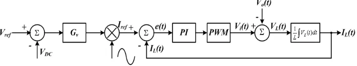
2. The Model Of The Power Circuit
Figure 1. Full bridge inverter
The output current is controlled by imposing the derivative of the current through the inductor, or, put differently, by imposing the voltage across the inductor L. In this manner, the structure of the converter shown in Figure 2 can be represented, without loss of generality, as the controlled voltage source Vi, presented in Figure 2, where the link inductors are represented by the inductor L, Vo is the utility voltage, and iL is the output PV system current.
Figure 2. Simplified equivalent inverter circuit
In Figure 2, the energy flow is controlled by the current iL. However, this current is defined by the difference of voltage between the sources Vi and Vo, applied across the impedance. In this case, as the impedance is a pure inductance, the current will be equal to the integral of the voltage across it.
As Vo is known, once it is the utility voltage itself, Vi is imposed and therefore VL. Thus:
( ) ( ) ( )
L i o
V t V t V t (2.1)
PWM defines a modulated signal composed of the reproduction of the modulating signal’s spectrum, whose amplitude is defined by the modulation, added to harmonic components of frequencies that are multiples of the switching frequency. Ignoring the effect of the harmonic components of the switching frequency on voltage Vi, once the inductor works as a low pass filter for the current, the voltage imposed across the inductor is represented simply by (2.1). Figure 3 shows the manner in which the converter allows the voltage to be imposed across the inductor, as shown in the equivalent circuit of Figure 2.
voltage drop across the inductor to be much smaller than the utility voltage. In other words, the sine of Vi dominates the cosine, demonstrating that the demand on the current loop is much more in favor of annulling the "disturbance" of the utility voltage rather than to effectively control the output current.
Figure 3. Block diagram of the simplified equivalent circuit.
(2.2)
(2.3)
(2.4)
3. The Current Control Strategy Of The Inverter In Stationary Reference Frame
In the control strategy, an internal current loop and an external loop to control the input voltage are implemented. The voltage loop defines the amplitude of the reference current by multiplying its control signal by a “waveform”, which can be a sample of the output voltage or a digitally generated sinusoid, generating the output current reference.
3.1 Classic PI control strategy
Figure 4 demonstrates how the classic PI control strategy is implemented, in which Vi is determined by the current error signal passing through the compensator. The error signal is the difference between a sample of the current and its reference.
Figure 4. Block diagram of classical PI control strategy current loop
It is observed, however, that the output voltage Vo appears as a disturbance in the simplified traditional model. From the block diagram, the current signal error is equal to
( ) Lref( ) L( )
e t i t i t . Since a perfectly sinusoidal current to the utility line is a design goal, e must naturally approach zero. So, there are two tasks that PI-controller has to operate: tracking reference current and rejecting disturbance voltage [1]-[2].
However, when the reference current is a direct signal, zero steady-state error can be secured by using a classic proportional-integral (PI) controller. When the reference current is a
( ) 2 sin( ) L
I t I t
( )
( ) L 2 cos( ) L
di t
V t L LI t
dt
( ) 2 cos( ) 2 sin( )
i RMS RMS
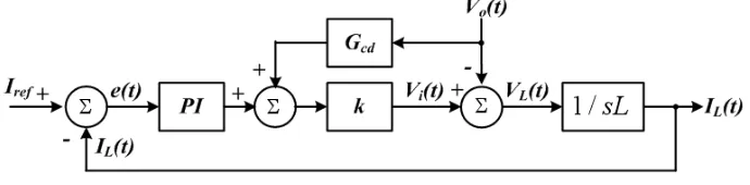
3.2 Classic PI control strategy with feed-forward
As the grid voltage is measurable, the forward feedback controller Gcd is used to reduce steady-state error of the controller due to the finite gain of PI, as shown in Figure 5. The
model of PWM is the k, and 2
ri
e k
V
, Where Vtri is the peak of the triangular carrier signal and e2
is the input of the PWM.
Figure 5. Block diagram containing the feed-forward controller
From the proposed block diagram that contains this feed-forward controller, it can be seen that:
(3.1)
From (3.1), when Gcd=1/k, the disturbance from Vo can be eliminated, and if
( i) p
k
k k sL
s
, then iL= iref, identifying the accurate current control effect for iref.
PI control with grid voltage feed-forward is commonly used for current-controlled PV inverters, but this solution exhibits two well known drawbacks: not enough ability of the PI controller to track a sinusoidal reference without steady-state error and poor disturbance rejection capability [3]-[5]. This is due to the poor performance of the integral action. Moreover; this leads in turn to the presence of the grid-voltage background harmonics in the current waveform. Thus, a poor THD of the current will typically be obtained.
3.3 The Proportion+Resonant(PR) regulator in stationary reference frame 3.3.1 Cosine function based on the internal model principle
New stationary reference frame control method that is based on the internal model principle in control theory. The method introduces a sine transfer function with a specified resonant frequency into the current compensator. Thus, the gain of the open-loop transfer function of the control system goes to infinity at the resonant frequency, which ensures that the steady-state errors in response to step changes in a reference signal at that frequency reduces to zero.
Consider the control system in which the reference input signal is sinusoidal. Based on the internal model principle [6], the compensator with a sinusoidal transfer function is required. There are two alternatives for the sine transfer function. One is the Laplace transform of a cosine function, and the other is that of a sine function. They are given by
2
1 2 2, 2 2 2
c c s G G s s . 0 1
1
(
)
(
)
( )
(
)
ref i p cd L L i pk
k k
k G
s
k
i s
i
V
k
sL
kC
sL
k k
s
Compared the Bode diagrams of Gc1 and Gc2 in Figure 6, It is observed that Gc1 has a sufficient amount of phase margin, 90 degree, but the phase margin of Gc2 is only 0 degree. Therefore, if Gc2 is employed for the sinusoidal internal model, the feedback control system would probably be highly underdamped. Therefore, it is important to note that the cosine function, Gcl, should be chosen for the sinusoidal internal model. In this paper, Gc1 is called the sine transfer function. The gain of the sine transfer function is theoretically infinite at the resonant angular frequency; namely, the gain of the loop transfer function goes to infinity at grid frequency 0. Figure 7 shows the block diagram of the sinusoidal internal model Gc1, where the input and output are u and y, respectively; and the gain is Ks [7].
Figure 6. Bode diagram of two transfer functions, Gc1 and Gc2
Figure 7. Block diagram of sinusoidal internal model Gc1 based on cosine function
3.3.2 The second order generalized integrator for a single sinusoidal signal
The paper proposes the concept of integrators for sinusoidal signals. The concepts of ideal integrator for a single sinusoidal signal and a stationary-frame ideal integrator for sinusoidal signals are explored [8].
(3.2)
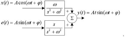
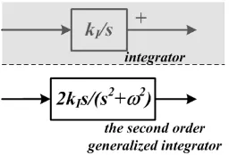
Then an ideal integrator for a single sinusoidal signal can be configured as shown in Figure 8. It is easy to get the result shown in Figure 9 from Figure 8 [9]. The corresponding stationary-frame generalized integrator is shown in Figure 9(c). The integrator output contains not only the integration of the input, but also an additional negligible component. The second order generalized integrator is shown in Figure 10, where KI is the integral constants [10]-[11].
Figure 8. An ideal integrator for a single sinusoidal signal
Figure 9. Signal passing through an ideal integrator
2 2 2 2 2 2 2 2 2 2 2 2
2 2 2 2
2 2 2 2
cos
sin
cos
sin
( )
(
)
(
)
cos
sin
( )
cos
sin
( )
s
A
As
As
A
Y s
s
s
s
s
s
s
A
As
E s
s
s
As
A
X s
s
s
Figure 10. Integrator and the second order generalized integrator
3.3.3 The Proportion+Resonant (PR) regulator
Form the above conclusions, it is explicit that both cosine function based on the internal
model principle, and the second order generalized integrator, have the same expression 2 s 2 s , but looking at issues from different views. The former, from the view point of frequency domain, explain how to get infinite gain at the resonant frequency, which ensures that the steady-state errors in response to reference sinusoidal signal reduces to zero. The latter, from the view point of time domain, explain the integrator concepts for sinusoidal signal, just like the integrator concepts for direct current signal.
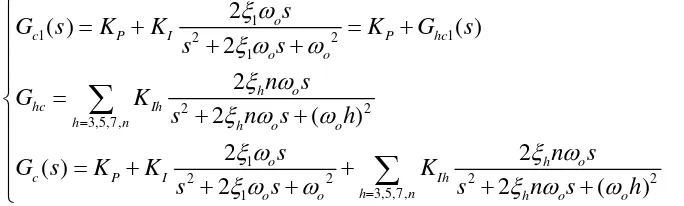
We call it, , resonant regulator, and the Proportion +Resonant (PR) current
controller Gc1 is defined as:
(3.3)
where, KP and KI are the proportional and integral constants respectively.
In the case of current control for grid connected inverter, the current error signal is nonsinusoidal, which contains multiple current harmonics. For each current harmonic of concern, a corresponding resonant regulator must be installed. When the multiple current harmonics are of concern, the corresponding resonant regulator should be installed. Resonant frequencies of the resonant regulator correspond to the frequencies of the concerned current harmonics. The harmonic compensator (HC) Ghc is defined as below,
(3.4)
Commonly; it is designed to compensate the selected harmonics 3rd, 5th and 7th, as they are the most prominent harmonics in the current spectrum.[12]-[14]
Using (3.3), (3.4), the transfer function of the generalized resonant regulator Gc can be expressed as
(3.5)
Figure 11 shows a more detailed picture of the standard controller scheme of Gc for the single-phase grid-connected PV inverter (the PWM modulator is intentionally omitted).
2 2
s
s
1
( )
2 2 1( )
c P I P hc
s
G
s
K
K
K
G
s
s
2 2
3,5,7,
(
)
hc Ih
h n o
s
G
K
s
h
2 2 2 2
3,5,7,
( )
(
)
c P I Ih
h n o
s
s
G s
K
K
K
s
s
h
Figure 11. standard controller scheme of Gc
Figure 12. Bode plot of disturbance rejection (current error ratio disturbance) of the PR+HC, P and PR current controllers.
The Bode plots of disturbance rejection for the PI and PR controllers are
shown in Figure 12, where: ε is current error and the grid voltage Vo is grid voltage, considered as the disturbance for the system [14].
As it can be observed, around the fundamental frequency the PR provides 140 dB attenuation, while the PI provides only 17 dB. Moreover around the 5th and 7th harmonics the situation is even worst, the PR attenuation being 125 dB and the PI attenuation only 8 dB. Moreover from Figure 12, it is clear that the PI rejection capability at 5th and 7th harmonic is comparable with that one of a simple proportional controller, the integral action being irrelevant. Thus it is demonstrated the superiority of the PR controller respect to the PI in terms of harmonic current rejection.
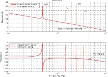
The open loop and closed loop frequency response of the system using PR controller can be seen in Figure 13 and Figure 14 respectively [15].
Figure 13. Bode plot of open-loop PR current control system 0
( )
( )
ref o i
s
V s
Figure 14. Bode plot of reference signal to grid current transfer function (closed loop)
3.3.4 The damped PR regulator
The PR regulator, exhibit theoretically an infinite gain at the resonance frequency, ensuring a nearly perfect harmonic elimination. However, the realization of ideal generalized integrators is sometimes not possible due to finite precision in digital systems, and the gain, at the resonance frequency, is easy to be affected by the fluctuation of the grid frequency.
Thus, a damped generalized integrator is proposed in which have limited gain at the resonance frequency. This configuration can be realized in digital platforms with a high accuracy and, moreover, it is well suited for alleviating some instability problems identified in ideal integrators [16]-[18].
(3.6)
Using the band-pass filters Ghc1 and Ghc, which are expressed in (3.6), the reference
signal to grid current transfer function exhibits both a larger bandwidth and smaller magnitude dips.
3.3.5 The optimum damped PR regulator
Figure 14 shows the Bode diagram of the reference signal to the grid current transfer function. A flat unity gain and zero phase are observed within the frequency range of interest. In that case, a good reference-signal-tracking capability is expected. However, this feature forces the reference signal to be a nearly perfect sinusoidal waveform with an insignificant harmonic content. In fact, the flat unity-gain and zero phase characteristics suggest that the grid current will track the fundamental reference signal and its harmonics perfectly.
1
1 2 2 1
1
2 2
3,5,7,
1
2 2 2 2
3,5,7, 1
2
( )
( )
2
2
2
(
)
2
2
( )
2
2
(
)
o
c P I P hc
o o
h o
hc Ih
h n h o o
o h o
c P I Ih
h n
o o h o o
s
G
s
K
K
K
G
s
s
s
n
s
G
K
s
n
s
h
s
n
s
G s
K
K
K
s
s
s
n
s
h
Figure 15. The optimum damped PR regulator
Paper [19]-[20] presents a current control scheme for the single phase grid-connected PV inverter with the following interesting features: 1) accurate synchronization with the grid voltage; 2) low harmonic content of the grid current; and 3) low computational load. Figure 15 shows the proposed current control scheme. Figure 16 shows the Bode diagram of reference signal to grid current transfer function
Figure 16. Bode diagram of reference signal to grid current transfer function (closed loop)
As expected, the reference signal to grid current transfer function behaves as a low-bandwidth band pass filter tuned to resonate at the grid frequency. Note that the transfer function magnitude and phase are 0 dB and 0◦ at 50 Hz, respectively, which suggests that a good tracking capability of the fundamental grid voltage component is achieved. Moreover, a significant additional attenuation is observed in Fig. 16 in the shape of the four narrow dips that are centered at frequencies of 150, 250, 350, and 450Hz, respectively. This behavior confirms that the simple and accurate synchronization method used in the proposed control scheme will not introduce the harmonic content of the reference signal into the grid current. Moreover; the
Bode plots of disturbance rejection for the optimum damped PR regulator controllers
is the same as Figure 12. Thus it is demonstrated the optimum PR controller has same superiority in terms of harmonic current rejection. Meanwhile; it is worth mentioning that the PLL-based synchronizing algorithm is not used in this system with the optimum damped PR regulator, so the computational load is necessarily lower due to without processing time required to compute the PLL synchronizing algorithm.
0
( )
( )
ref o i
s
V s
3.3.6 The other non-mainstream regulator
Hysteresis controller [21]-[24] is worth noticing that in the case of hysteresis control implementation, an adaptive band of the controller has to be designed to obtain fixed switching frequency. However it has major drawbacks in variable switching rate, current error of twice the hysteresis band, and high-frequency limit-cycle operation.
The dead-beat controller [25] attempts to null the error with one sample delay. Since dead-beat controller regulates the current such that it reaches its reference at the end of the next switching period, the controller introduces one sample time delay. To compensate for this delay, an observer should be introduced in the structure of the controller, with the aim to modify the current reference to compensate for the delay. Performance of the prediction [26]-[28], on the other hand, is subject to accuracy of the plant model as well as accuracy of the reference current prediction.
A sliding-mode current controller [29]-[30] for a grid-connected PV system is proposed to provide a robust tracking against the uncertainties within the system. The controller is designed based on a time-varying sliding surface. However, the selection of a time-varying surface is a difficult task and the system stays confined to the sliding surface. Moreover, some intelligent control techniques such as neural network, genetic algorithm, fuzzy logic, etc. are used, and these methods extend the search space significantly. However, the intelligent control techniques cannot capture the dynamics of the system accurately and the model-based controllers are more useful to perform this task efficiently.
4. The Current Control Strategy Of The Inverter In Dq Rotating Reference Frame
Although for a three phase converter simple PI compensators designed in a dq rotating frame can achieve zero steady state error at the fundamental frequency and improve its dynamic response, this method is not readily applicable to single-phase power converters because there is only one phase variable available in single-phase power converter, while the dq transformation needs at least two orthogonal variables.
In order to construct the additional orthogonal phase information from the original single-phase power converter, we introduced the Imaginary Orthogonal Circuit concept, as shown in Figure 17. The Imaginary Orthogonal Circuit has exactly the same circuit components and parameters, e.g. power switches, inductors and capacitors. Ideally the state variables and control references, such as the inductor current iL and the grid voltage Vo, maintain 90 phase
shift with respect to their counterparts in the Real Circuit IL-R and Vo-R. In other words, the
Imaginary Circuit variable XI (including II and VI) is orthogonal to the Real Circuit variable XR,
(including IR and VR), as shown in Figure 18. Although the Imaginary Circuit does not physically
exist, it is possible to construct its state variables from the Real Circuit state variables.
As shown in Figure 18, assuming the steady state Real Circuit variable is expressed as , where XM, is the peak value of the sinusoidal waveform, is the initial
phase and is the fundamental frequency. Ideally the corresponding Imaginary Orthogonal Circuit variable would be . Applying the rotating transformation matrix to the stationary Real and Imaginary Circuit variables, the variables in the dq rotating frame become
(4.1)
where the variables in the rotating frame Xd, and Xq may represent either the voltages or the
currents in the rotating frame.
It is important to notice that the variables in the rotating frame become constants (DC values), as shown in (4.1). Those DC values define the DC operating point of the single-phase converters in the rotating DQ frame. All the control methods developed for DC/DC converters can be applied.
X
R
X
Mcos(
t
)
X
I
X
Msin(
t
)
cos
cos
sin
,
sin
sin
cos
d R
M
q I
X
X
t
t
T
X
T
X
X
t
t
Figure 17. Rea Circuit and its Imaginary Orthogonal Circuit
Figure 18. Real Circuit and Imaginary Orthogonal Circuit Variables
4.1 The model of the power circuit in rotating reference frame
The equivalent circuit of the single-phase VSI for grid connected system is shown in Figure 2. The equivalent circuit, voltage vector can be written voltage equation in the stationary reference frame αβ with Kirchhoff’s voltage law (KVL) as follows [31]-[33]:
(4.2)
where IL is the output current components of the inverter in the stationary reference
frame αβ, and L is the inductance. If considering the parasitic resistance of inductance R, the equation is
(4.3) L R
i R o R
L I
i I o I
dI
V
L
V
dt
dI
V
L
V
dt
L R
i R L R o R
L I
i I L I o I
dI
V
RI
L
V
dt
dI
V
RI
L
V
dt
Applying the dq rotating transformation to (4.3), the resultant circuit model in the dq rotating frame is expressed in (4.4), and the circuit model is shown in Figure 19.
(4.4)
Notice that in the stationary frame the steady state output voltages are sinusoidal, while in the dq rotating frame the steady state voltages are constant DC values. The cross-coupling terms are introduced due to the rotating transformation, and they can be decoupled in the controller design.
Figure 19. The power circuit model in the dq rotating reference frame
4.2 Classic PI control strategy in the in rotating reference frame
Compensator design in the DQ rotating frame is similar to that of DCDC converters. Generally classic PI control strategy is used to to eliminate steady error, as shown in Figure 20 [34]-[37].
0
+
0
L d L d i d o d L d
L q L q i q o q L q
i d d
DC
i q q
I
d
I
V
V
L
I
R
L
I
dt
I
V
V
L
I
V
D
V
V
D
Figure 20. Block diagram of PI control in the rotating reference frame
Combining the power circuit and control circuit mathematical model of the functional modules of the transfer function, the mathematical model of current control loop for grid-connected inverter is obtained, as shown in Figure 21. As shown in Figure 21, the Vo-d,Vo-q,
, and are the disturbance of the current loop.
Figure 21. The model of current control loop for Figure 20
4.3 Classic PI control strategy with feed-forward in the in rotating reference frame
In order to relieve the pain of performing the task of the PI controller, and to make system have rapid speed response of anti-disturbance ability, a new PI control strategy with feed-forward is also proposed, as shown in Figure 22, and model of current control loop is presented in Figure 23 [38]-[42].
L d
I
L
Figure 22. Block diagram of PI control with feed-forward in the rotating frame
Figure 23. The model of current control loop for Figure 22
In this structure, the dc-link voltage is controlled in accordance to the necessary output power. Its output is the reference for the active current controller, whereas the reference for the reactive current is usually set to zero, if the reactive power control is not allowed. In the case that the reactive power has to be controlled, a reactive power reference must be imposed to the system. For improving the performance of PI controller, depicted in Figure 22, cross-coupling terms and voltage feed-forward are usually used. In any case, with all these improvements, the compensation capability of the low-order harmonics in the case of PI controllers is very poor, standing as a major drawback when using it in grid-connected systems.
5. Conclusions
frame and rotating reference frame is presented, and their major characteristics were pointed out. A discussion about different controllers and their ability to compensate for grid disturbance was also given.
Acknowledgments
Great supports were given by Natural Science Foundation of China (No. 51277004) and The Importation and Development of High-Caliber Talents Project of Beijing Municipal
Institutions (IDHT20130501).
References
[1] Somkun S., Sehakul P., Chunkag V. Novel control technique of single-phase PWM rectifier by compensating output ripple voltage. Industrial Technology, 2005. ICIT 2005. IEEE International Conference on. 2005: 969 – 974. [DOI: 10.1109 / ICIT. 2005. 1600776]
[2] Kleber CA., De Souza, Walbermark M. dos Santos,Denizar C. Martins. Active and reactive power control for a single-phase grid-connected PV system with optimization of the ferrite core volume.
Industry Applications (INDUSCON), 2010 9th IEEE/IAS International Conference on. 2010: 1 – 6. [DOI: 10.1109/INDUSCON.2010.5740003]
[3] Yuansheng Xiong, Suxiang Qian, Jianming Xu. Single-Phase Grid-Connected Photovoltaic System Based on Boost Inverter. Power and Energy Engineering Conference (APPEEC), 2012 Asia-Pacific. 2012: 1 – 3. [DOI: 10.1109 /APPEEC.2012.6307194 ]
[4] J. Selvaraj, NA. Rahim. Multilevel inverter for grid-connected PV system employing digital PI controller. IEEE Trans.Ind. Electron. 2009; 56(1): 149–158. [DOI: 10.1109/TIE.2008.928116 ] [5] PP. Dash, M. Kazerani. Dynamic modeling and performance analysis of a grid-connected
current-source inverter-based photovoltaic system. IEEE Trans.Sustain. Energy. 2011; 2(4): 443–450. [DOI: 10.1109/TSTE.2011.2149551 ]
[6] Bernard Friedland. Advanced Control System Design. 1st edition. Prentice-Hall, Inc 1996: 131-147. [7] Fukuda S., Yoda T. A novel current-tracking method for active filters based on a sinusoidal internal
model. Industry Applications, IEEE Transactions on. 37(3): 888 – 895. [DOI: 10.1109/28.924772] [8] Wang TCY, Xiaoming Yuan. Design of multiple-reference-frame PI controller for power converters.
Power Electronics Specialists Conference, 2004. PESC 04. 2004 IEEE 35th Annual. 2004; 5: 3331 – 3335. [DIO: 10.1109/ PESC.2004.1355064]
[9] Xiaoming Yuan, Merk W., Stemmler H., Allmeling J. Stationary frame generalized integrators for current control of active power filters with zero steady-state error for current harmonics of concern under unbalanced and distorted operating conditions. Industry Applications, IEEE Transactions on. 2002; 38(2): 523 – 532. [DIO: 10.1109/28.993175]
[10] Xiaoming Yuan, Merk W. the Non-Ideal Generalized Amplitude Integrator (NGAI): Interpretation, Implementation and Applications. Power Electronics Specialists Conference, 2001. PESC. 2001 IEEE 32nd Annual. 2001; 4: 1857 – 1861. [ DOI: 10.1109/PESC.2001.954392]
[11] Zmood DN, Holmes DG., Bode GH. Frequency domain analysis of three phase linear current regulators. Industry Applications, IEEE Transactions. 2001; 37(2): 601–610. [DOI: 10.1109/28.913727 ]
[12] Teodorescu R., Blaabjerg F., Borup U., Liserre M. A new control structure for grid-connected LCL PV inverters with zero steady-state error and selective harmonic compensation. Applied Power Electronics Conference and Exposition, 2004. APEC '04. Nineteenth Annual IEEE. 2004; 1: 580–586. [DOI: 10.1109/APEC.2004.1295865 ]
[13] Liserre M., Teodorescu R., Blaabjerg F. stability of pv and wind turbine grid connected inverters for a large set of grid impedance values. Power Electronics, IEEE Transactions on. 2006; 21(1): 263–272. [DOI: 10.1109 /TPEL.2005.861185]
[14] Castilla M., Miret J., Matas J., deVicua LG., Guerrero JM. Linear Current Control Scheme With Series Resonant Harmonic Compensator for Single-Phase Grid-Connected Photovoltaic Inverters. Industrial Electronics, IEEE Transactions on. 2008; 55(7): 2724-2733. [DOI: 10.1109/TIE.2008.920585]
[15] Castilla M., Miret J., Matas J., Garcia de Vicuna L., Guerrero JM. Control design guidelines for single-phase grid-connected photovoltaic inverters with damped resonant harmonic compensators.
Industrial Electronics, IEEE Transactions on.2009; 56(11): 4492–4501. [DOI: 10.1109 /TIE.2009.2017820]
[16] Keliang Zhou, Zhipeng Qiu, Watson NR., Yonghe Liu. Mechanism and elimination of harmonic current injection from single-phase grid-connected PWM converters. Power Electronics, IET. 2013; 6(1): 88–95. [DOI: 10.1049/iet-pel.2012.0291 ]
10.1109/TPEL.2013.2238557 ]
[18] Yongheng Yang, Keliang Zhou, Blaabjerg F. Harmonics suppression for single-phase grid-connected PV systems in different operation modes. Applied Power Electronics Conference and Exposition (APEC), 2013 Twenty-Eighth Annual IEEE. 2013: 889–896. [DOI: 10.1109/APEC.2013.6520316 ] [19] Rashed M., Klumpner C., Asher G. Repetitive and Resonant Control for a Single-Phase
Grid-Connected Hybrid Cascaded Multilevel Converter. Power Electronics, IEEE Transactions on. 2013; 28(5): 2224–2234. [DOI: 10.1109/TPEL.2012.2218833 ]
[20] M. Rashed, C. Klumpner, G. Asher. Control scheme for a single phase hybrid multilevel converter using repetitive and resonant control approaches. in Proc. 14th Eur. Conf. Power Electron. Appl. 2011: 1–13.
[21] Zhilei Yao, Lan Xiao. Control of Single-Phase Grid-Connected Inverters With Nonlinear Loads.
Industrial Electronics, IEEE Transactions. 2013; 60(4): 1384-1389 [DOI: 10.1109/TIE.2011.2174535 ] [22] Zhilei Yao, Lan Xiao, Yangguang Yan. Seamless Transfer of Single Phase Grid Interactive Inverters Between Grid Connected and Stand Alone Modes. Power Electronics, IEEE Transactions on. 2010; 25(6): 1597–1603. [DOI: 10.1109/TPEL.2009.2039357 ]
[23] Wannakarn P., Kinnares V. Single-phase grid connected axial flux permanent magnet generator system with reactive power compensation functionality. IPEC, 2012 Conference on Power & Energy. 2012: 338–341. [DOI: 10.1109/ASSCC.2012.6523289 ]
[24] NA. Rahim, J. Selvaraj, CC. Krismadinata. Hysteresis current control and sensorless MPPT for grid-connected photovoltaic systems. in Proc. IEEE Int. Symp. Industrial Electronics, Vigo, Spain. 2007: 572–577. [DOI: 10.1109/ISIE.2007.4374659 ]
[25] Trung-Kien Vu, Byung-Moon Han, Hanju Cha. A new adaptive dead-time compensation for single-phase grid-connected PV inverter. Applied Power Electronics Conference and Exposition (APEC), 2011 Twenty-Sixth Annual IEEE. 2011: 923–930. [DOI: 10.1109/APEC.2011.5744705 ]
[26] Mosa M., Abu-Rub H., Ahmed ME., Kouzou A., Rodriguez J. Control of single phase grid connected multilevel inverter using model predictive control. Power Engineering, Energy and Electrical Drives (POWERENG), 2013 Fourth International Conference on. 2013: 624–628. [DOI: 10.1109 / PowerEng.2013.6635681]
[27] Sreeraj ES., Chatterjee K., Bandyopadhyay S. One Cycle Controlled Single Stage Single PhaseVoltage Sensorless Grid Connected PV System. Industrial Electronics, IEEE Transactions on. 2013; 60(3): 1216-1224. [DOI: 10.1109/TIE.2012.2191755]
[28] A. Kotsopoulos, JL. Duarte, MAM. Hendrix. A predictive control scheme for DC voltage and AC current in grid-connected photovoltaic inverters with minimum DC link capacitance. in Proc. 27th Annu. Conf. IEEE Industrial Electronics Society, Colorado, USA. 2001: 1994–1999. [DOI: 10.1109/IECON.2001.975597 ]
[29] Xiang Hao, Xu Yang, Tao Liu, Lang Huang, Wenjie Chen. a sliding-mode controller with Multiresonant sliding surface for Single Phase Grid Connected VSI With an LCL filter. Power Electronics, IEEE Transactions on. 2013; 28(5): 2259–2268. [DOI: 10.1109/TPEL.2012.2218133 ] [30] Li Liang, Xie Jian, Li Wei. Fuzzy adaptive PID control of a new hydraulic erecting mechanism.
TELKOMNIKA Telecommunication Computing Electronics and Control. 2013; 11(4): 715-724. [DOI]: 10.12928/TELKOMNIKA.v11i4.1159
[31] Ebrahimi M., Karshenas HR., Hassanzahraee M. Comparison of orthogonal quantity generation methods used in single-phase grid-connected inverters. IECON 2012 - 38th Annual Conference on IEEE Industrial Electronics Society. 2012: 5932–5937. [DOI: 10.1109/IECON.2012.6389112 ]
[32] Benjanarasut J., Neammanee B. The d-, q- axis control technique of single phase gridconnected converter for wind turbines with MPPT and anti-islanding protection. Electrical Engineering/Electronics, Computer, Telecommunications and Information Technology (ECTI-CON), 2011 8th International Conference on. 2011: 649–652. [DIO: 10.1109/ECTICON.2011.5947923 ] [33] Chi Yao Wu, Ching Heng Chen, Jhe Wei Cao, MingTai Liu. Power control and pulsation decoupling
in a single-phase grid-connected voltage-source inverter. TENCON Spring Conference, 2013 IEEE. 2013: 475–479. [DOI: 10.1109/TENCONSpring.2013.6584490 ]
[34] Lekgamheng N., Kumsuwan Y. Power analysis of single phase grid connected photovoltaic systems based on two-stage current source converters. Electrical Engineering/Electronics, Computer, Telecommunications and Information Technology (ECTI-CON), 2012 9th International Conference on. 2012: 1–4. [ DOI: 10.1109/ECTICon.2012.6254121 ]
[35] Bojoi R., Roiu D., Griva G., Tenconi A. Single-phase grid-connected distributed generation system with Maximum Power Tracking. Optimization of Electrical and Electronic Equipment (OPTIM), 2010 12th International Conference on. 2010: 1131–1137. [DOI: 10.1109/OPTIM.2010.5510331 ]
[36] Seon-Hwan Hwang, Liming Liu, Hui Li, Jang-Mok Kim. DC Offset Error Compensation for Synchronous Reference Frame PLL in Single Phase Grid Connected Converters. Power Electronics, IEEE Transactions on. 2012; 27(8): 3467-3471. [DOI: 10.1109/TPEL.2012.2190425 ]
[37] Elrayyah A., Safayet A., Sozer Y., Husain I., Elbuluk M. Efficient Harmonic and Phase Estimator
[38] Crowhurst B., El-Saadany EF., El Chaar L., Lamont LA. Single phase grid tie inverter control using DQ transform for active and reactive load power compensation. Power and Energy (PECon), 2010 IEEE International Conference on. 2010: 489-494. [DOI: 10.1109/PECON.2010.5697632 ]
[39] Zhang R., Cardinal M., Szczesny P., Dame M. A grid simulator with control of single-phase power converters in D-Q rotating frame. Power Electronics Specialists Conference, 2002. PESC 02. 2002 IEEE 33rd Annual. 2002; 3: 1431-1436. [DOI: 10.1109/PSEC.2002.1022377 ]
[40] Samerchur S., Premrudeepreechacharn S., Kumsuwun Y., Higuchi K. Power Control of Single-Phase Voltage Source Inverter for Grid-Connected Photovoltaic Systems. Power Systems Conference and Exposition (PSCE), 2011 IEEE/PES. 2011: 1-6. [DOI: 10.1109/PSCE.2011.5772504 ]
[41] Zhigang Liang, Alesi L., Xiaohu Zhou, Huang AQ. Digital Controller Development for Grid-Tied Photovoltaic Inverter with Model Based Technique. Applied Power Electronics Conference and Exposition (APEC), 2010 Twenty-Fifth Annual IEEE. 2010: 849–853. [DOI: 10.1109/APEC.2010.5433570 ]