MOHD HASBULLAH BIN PUTRA
This Report Is Submitted In Partial Fulfillment of Requirements For The Bachelor Degree in Electronic Engineering (Industrial electronics)
Fakulti Kejuruteraan Elektronik dan Kejuruteraan Komputer Universiti Teknikal Malaysia Melaka
DECLARATION
UNIVERSTI TEKNIKAL MALAYSIA MELAKA
FAKULTI KEJURUTERAAN ELEKTRONIK DAN KEJURUTERAAN KOMPUTER
BORANG PENGESAHAN STATUS LAPORAN PROJEK SARJANA MUDA II
Tajuk Projek : DESIGN AND IMPLEMENTATION OF LINE CAMERA BASED LANE FOLLOWING INTELLIGENT VEHICLE CONTROL SYSTEM
Sesi
Pengajian : 1 4 / 1 5
Saya MOHD HASBULLAH BIN PUTRA mengaku membenarkan Laporan Projek Sarjana Muda ini disimpan di Perpustakaan dengan syarat-syarat kegunaan seperti berikut:
1. Laporan adalah hakmilik Universiti Teknikal Malaysia Melaka.
2. Perpustakaan dibenarkan membuat salinan untuk tujuan pengajian sahaja.
3. Perpustakaan dibenarkan membuat salinan laporan ini sebagai bahan pertukaran antara institusi pengajian tinggi.
4. Sila tandakan ( √ ) :
SULIT* *(Mengandungi maklumat yang berdarjah keselamatan atau kepentingan Malaysia seperti yang termaktub di dalam AKTA RAHSIA RASMI 1972)
TERHAD** **(Mengandungi maklumat terhad yang telah ditentukan oleh organisasi/badan di mana penyelidikan dijalankan)
TIDAK TERHAD
Disahkan oleh:
__________________________ ___________________________________ (TANDATANGAN PENULIS) (COP DAN TANDATANGAN PENYELIA)
i ABSTRACT
A line scan camera based lane following robot is an autonomous robot build for the Freescalecup™ competition. The Freescale™ racing car which builds up with a line scan camera and peripheral actuators such as motors are expected to complete the racing track which provided by Freescale™. The camera will provide the KL25Z microprocessor with signal representing the line scan result, a cross section line representing the upcoming track. In order to understand the signals provide by the camera, a real-time system to monitor the input signal is made. The digitized signal will be transferred from the KL25Z microprocessor wirelessly (Wi-Fi) to the monitoring PC. The received data will then be analysed in real-time with Matlab. Apart from the signal monitoring the Freescale™ racing car also need to undergo calibrating procedure to ensure the performance of the system is at the maximum level. The overall system is modelled into a closed loop system which allows the robot to manoeuvre and complete the racing track. PD controller is added to the closed loop for error compensation and to stabilize the system
ii ABSTRAK
iii ACKNOWLEDGEMENT
iv APPROVAL
I hereby declare that I have read this report and in my opinion this report is sufficient in terms of scope and quality for the award of Bachelor of Electronics Engineering
(Industrial Electronics)
Signature :……….
Name :……….
v DECLARATION
I hereby declare that this thesis entitled “DESIGN AND IMPLEMENTATION OF LINE CAMERA BASED LANE FOLLOWING INTELLIGENT VEHICLE CONTROL SYSTEM” is the result of my own research except as cited in the references.
Signature :……….
Name :MOHD HASBULLAH BIN PUTRA
vi LIST OF TABLES
TABLE TITLE PAGE
2.1 Comparison of Image Sensor 16
3.1 Relationship between the DC and servo motor with the movement of the Freescale™ cup racing car
20
4.1 Freescale™ cup racing car locomotion logging 34 4.2 Character send to the Freescale™ cup racing car and the
command
36
vii LIST OF FIGURES
Figure TITLE PAGE
2.1 OzTUg Mobile Robot 4
2.2 Prototype of line following robot proposed by Illnur and Deniz
4
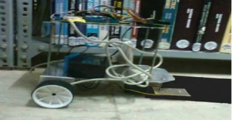
2.3 Book searching and arranging operation of the line following robot
5
2.4 Placement of Infrared Sensors 6
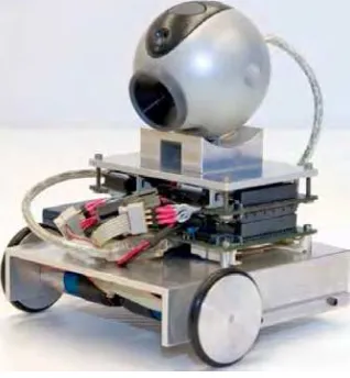
2.5 Webcam based Mobile Robot 6
2.6 Serial Communication with PC 7
2.7 UART Module Block Diagram 8
2.8 Electromagnetism concept inside the DCmotor 9
2.9 Torque generation in DC motor 9
2.10 H-bridge configurations 10
2.11 Motion created by the H-Bridge 10
2.12 Pulse width modulation (PWM) 11
2.13 PID Controller Block Diagram 12
2.14 Connection Infrared Sensor 13
2.15 Block Diagram of CCD Image Sensor 14
2.16 Block Diagram of CMOS Image Sensor 15
viii 3.2 Locomotion of the Freescale™ cup racing car 19
3.3 interface of the TCP/IP Wi-Fi controller 21
3.4 Defining the Destination IP address 21
3.5 Defining the ASCII character sent for each button 22 3.6 Hardware and software tools involved for wireless data
logging
23
3.7 Camber alignment 24
3.8 Front wheel toe calibration 25
3.9 Rotary Encoder 26
3.10 Rotary Encoder to Arduino connection 26
3.11 Defined sample template to detect one of the black lanes. Multiple bright and dark pixels are used to increase the reliable of the correlation calculation
28
3.12 Flow chart of the template matching based black line centre detection.
29
3.13 Steps to determine the current location with template matching
29
4.1 the movement of the Freescale™ cup racing car 33
4.2 Wi-Fi Network connection 35
4.3 Controller Command setting 35
4.4 Examples of ASCII characters sent to the KL25Z microcontroller
ix
4.5 Zero camber calibration 37
4.6 Default toe calibration 37
4.7 PWM value versus measured RPM RIGHT 38
4.8 PWM value versus measured RPM LEFT 39
4.9 Comparison of RPM RIGHT and RPM LEFT 39
4.10 Histogram for RPM at PWM= 0.1 40
4.11 3D Camera Mounting design 41
4.12 Camera mounted on the 3D printed camera mounting 41
4.13 Camera viewing angle 42
4.14 Camera signal monitored signal from Matlab™ 42 4.15 Unfocused lens signal (5 pixels for black line) 43 4.16 Focused lens signal (10 pixels for the black line) 43
4.17 Light reflection on the black line 44
4.18 Reflective polarizer 44
4.19 Real time signal monitoring with actual condition 45
4.20 Straight line 46
4.21 Right Turn 46
4.22 Left Turn 47
4.23 Junction 47
x
4.26 Proportional constant,Kp = 0.105 50
4.27 Proportional constant, Kp = 0.084 50
4.28 Kd compensation on Kp value (Kd=0.125) 51
4.29 The Freescale™ cup racing car completing the edge lane track
xi LIST OF APPENDICES
Appendix TITLE PAGE
A Main Program 16
xii LIST OF ABBREVIATIONS
PD Proportional Derivative TCP/IP Transmission control Protocol
IR Infra red
ASCII American Standard Code Information Interchange PC Personal Computer
UART Universal Asynchronous Reciever Transmitter
TX Transmitter
RX Receiver
DC Direct Current
PWM Pulse Width Modulation
PID Proportional Integrad Derivative CCD Charged Couple Device
CMOS Complementary metal Oxide VGA Video Graphic Array
ADC Analog Digital Converter IP Internet Protocol
SCI Serial Communication Interface RPM Rotation per Minute
xiii TABLE OF CONTENTS
Content Page
ABSTRACT i
ABSTRAK ii
ACKNOWLEDGEMENT iii
APPROVAL iv
DECLARATION v
LIST OF TABLES vi
LIST OF FIGURES vii
LIST OF ABBREVIATION xi
CHAPTER
1. INTRODUCTION
1.1Background
1 1.2Problem Statement
2 1.3Objectives
2 1.4Scopes
2 1.5Overview
xiv
2. LITERATURE REVIEW
2.1Application of line following robot
3 3
2.2Existing Line following System
6 2.3Serial Communication
7 2.4Universal Asynchronous Receiver Transmitter (UART)
8 2.5DC motor and Half Bridge
9 2.6Servo motor
11 2.7Proportional Integral Derivative (PID) Control
12 2.8Sensor
13
3. METHODOLOGY
3.1Motion control identification for Freescale™ cup racing car.
17 18
3.2Defining the remote control command
20 3.3Data logging and monitoring
22 3.4Car chassis calibration
24 3.5Camera angle and lens fixing
27 3.6Camera angle and lens fixing
xv
4. RESULT AND DISCUSSION
4.1Wireless motion control and data logging for the Freescale™ cup racing car
32 33
4.2Minimization of physical errors on the Freescale™ cup racing
car 37
4.3Real time line scan camera signal processing
45
4.4Template Matching and error detection
48
4.5Servo actuation based on Proportional - Derivative control
49
5. CONCLUSION AND SUMMARY
5.1Conclusion
53 53
1 CHAPTER 1
INTRODUCTION
Nowadays, an autonomous technology is widely used especially in vehicle research and development. This technology is constantly emerging and has high potential commercial value in various fields. Thus from this potential Freescale™ is providing fundings to encourage students to innovate the autonomous lane following car.
1.1 Background
A line camera based lane following intelligent vehicle control system is an idea to satisfy the autonomous racing car for the Freescale™ cup. The Freescale™ cup is a global competition where student teams build, program, and race a model car around a racing track for speed without derailing from the track. This competition is believed to be a platform for the participants from around the globe to access to the latest technology and apply it by hands on.
The line camera based lane following intelligent vehicle control system is using the camera as the source of input to capture the signal of the racing track. The line scan camera is widely used in the industry due to its fast response and easy to analyse. From the camera the data will be further process by the KL25Z microcontroller. The microcontroller is then will send the appropriate output to the peripherals actuator to complete the autonomous control for the Freescale™ cup racing car. The overall system of the car will be further discussed in chapter 3.
2 1.2 Problem statement
The line camera based lane following intelligent vehicle control system need to be modelled in a closed loop system and the control is to be determined by the PD controller.
1.3 Objectives
1. To build a system to have better understanding on the human interaction with the freescale cup lane following car
2. To identify and minimize the physical system error for the Freescale™ cup racing car.
3. To identify and apply suitable real-time signal processing method for the freescale cup lane following car.
4. To design and implement Proportional-Differential (PD) servo controller for the freescale cup lane following car
1.4 Scopes
The scope of the project is limited to the rules and regulation stated by the organizer of the Freescale™ cup. The main focus of the project is to complete the Freescale™ racing track with the shortest time.
1.5 Overview
3 CHAPTER 2
LITERATURE REVIEW
In this chapter, the review on the application is being explained in Section 2.1. Different approach of robot might use different components. The design of the line following robot is being studied in Section 2.2 by comparing the existing line following robots. In addition, the topology of a serial communication is also being explained in Section 2.3. The serial communication will allow the robots to communicate with the personal computer. In conjunction with the serial port the UART are also being reviewed in Section 2.4. In this section the method for the microcontroller to transmit the data is being emphasized. The mechanical approach in Section 2.5 and 2.6 will allow further understanding on how the mechanism works. Then in Section 2.7 the PD controller which is the most important in the Freescale™ racing car is being explained in detail. In the last part, the comparison of the sensor being used is further discussed. The discussion will let point out the advantages and disadvantages of each system
2.1 Application of Line Following Robot
4 Figure 2.1: OzTUg Mobile Robot
Besides manufacturing environment, line following mobile robots also can be deployed as a commercial product. Illnur and Deniz (2009) proposed a design of a line following robot which is commonly used to carry visitor through shopping mall and entertainment fair. Figure 2.1.2 shows the prototype of the line following robot.
[image:22.612.154.554.465.581.2]5 Apart from that, Thirumurugan, Vinoth, Kartheeswaran and Vishwanathan (2010) demonstrated the application of line following robot for library inventory management system. In their design, a line following robot is designed using sensor operated motor to keep track the line path predetermined for library book shelf arrangements.
6 2.2 Existing Line Following Systems
[image:24.612.244.451.197.410.2]Line following capability can be achieved by a few methods; the most basic method is using the light sensor such as infrared sensor or colour sensor. Figure 2.2.1 illustrates the application and placement of infrared sensors in the design proposed by Illnur and Deniz (2009).
Figure 2.4: Placement of Infrared Sensors
Jean and Marc (2006) presented a webcam-based line following mobile robot equipped with a miniature Linux-based single-board computer as shown in Figure 2.2.2.
[image:24.612.266.425.504.676.2]