UNIVERSITI TEKNIKAL MALAYSIA MELAKA
DESIGN AND ANALYSIS OF BASE ASSEMBLY FOR FLANGE
RESURFACE MACHINE
This report submitted in accordance with requirement of the Universiti Teknikal Malaysia Melaka (UTeM) for the Bachelor’s Degree in Mechanical Engineering
Technology (Automotive Technology) (Hons.)
by
MOHAMAD ZAHURI BIN JAMIL
B071210422
930123086061
i
ABSTRACT
As the demand for maintaining the flange surface in oil and gas industry increases so does the need for high performance flange resurface machine. Thus, this final year project was performed with the goal to design and analysis the base assembly for the Flange Resurface Machine in order to reducing the weight due to the difficulties to operate the machine and to ensure the machining product is to meet the specifications of job site requirements. One of the key components of the flange resurface machine is the perfect rigid base assembly. After careful consideration, a few assessment have been taken into account to identify the factors and solution mainly on design and materials used. The three major factors were material selected, factor of vibration and surface finish design. Catia V5R20 design software was used to evaluate the potential design and analyse the statistical significance of each variable along with any interactions between variables. The complete proposed design are being analyse using three different computer aided software which is Solidthinking analysis, Catia analysis and Hypermesh analysis. Results showed that using the tools steel will reduce the weight compared to other metal with the same strength. The analysis also has shown a variety of results since the software used has it limit of capability to run the analysis. However, the overall result obtained were very delightful since the value of Von Mises Stress and Displacement that being taken as reference value was accepted. Last but not least, the improvement that can be done towards this research is to have a more longer timing to run this project and also to use other different type of analysis software in order to get the best analysis results.
ii
ABSTRAK
Peningkatan jumlah bilangan permintaan untuk menyelenggara permukaan bibir paip di industri minyak dan gas adalah selari dengan peningkatan keperluan “Flange Resurface Machine” yang berprestasi tinggi. Oleh itu, projek tahun akhir ini dilaksanakan dengan matlamat untuk mengurangkan berat tapak mesin kerana kesukaran untuk mengedalikan operasi mesin disamping memastikan hasil akhir produk adalah memenuhi spesifikasi seperti yang ditetapkan. Salah satu komponen terpenting mesin itu adalah pada tapak mesin tersebut kerana ianya menentukan samada gegaran yang terhasil dapat dibendung bagi memastikan operasi mesin berjalan dengan lancar. Beberapa penilaian telah diambil kira bagi mengenalpasti faktor-faktor dan penyelesaian terutama pada reka bentuk dan bahan yang digunakan. Catia V5R20 adalah perisian reka bentuk yang digunakan untuk menilai reka bentuk yang dihasikan dan menganalisis kepentingan statistik untuk setiap pembolehubah bagi mana-mana interaksi antara pembolehubah. Cadangan reka bentuk yang telah dihasilkan akan dianalisis menggunakan tiga bantuan perisian komputer iaitu SolidThinking, analisis Catia dan analisis Hypermesh. Hasil kajian yang diperoleh menunjukkan bahawa menggunakan bahan logam tool steel akan mengurangkan
iii
DEDICATIONS
This Research Paper is lovingly dedicated to my respective parents who have been my constant source of inspiration. They have given me the drive and discipline to tackle any task with enthusiasm and determination. Without their support this project
iv
ACKNOWLEDGMENTS
My first and foremost gratitude is to Allah because has giving me strength to complete this report. I would like to express my deepest gratitude to my supervisor who provided me the possibility to complete this project. I am highly indebted to En Adnan Bin Katijan for his guidance and constant attention as well as for providing valuable suggestion, enthusiastic support and personal concern during the project.
Furthermore, my appreciation also goes to business development manager Mohd Nasibi Samsuddin from the Perfect Emerald SDN BHD and to the Department of Mechanical Technology Engineering for the permission to use the facilities and equipment available at their department which aided me to complete this project successfully.
v
TABLE OF CONTENTS
ABSTRACT ... i
ABSTRAK ... ii
DEDICATIONS ... iii
ACKNOWLEDGMENTS... iv
TABLE OF CONTENTS ... v
LIST OF FIGURES... viii
LIST OF TABLE ... x
LIST OF SYMBOLS AND ABBREVIATIONS ... xi
CHAPTER 1... 1
1.0 Introduction ... 1
1.1 Background... 1
1.2 Problem Statement... 2
1.3 Objetives ... 2
1.4 Work Scopes ... 2
CHAPTER 2... 3
2.0 Introduction ... 3
2.1 Flange Resurface Machine ... 4
2.1.1 Base Assembly ... 5
2.2 Materials ... 5
vi
2.2.2 Mild Steel ... 6
2.2.3 Stainless Steel... 7
2.3 Surface Finish ... 9
2.3.1 Friction ... 10
2.3.2 Surface Finish Shape ... 11
2.3.3 End Surface Finish ... 15
2.3.3.1 Surface Finish for Gasket ... 16
2.3.3.2 Smooth Finish for Ring Type Joint Flange or Raised-Face Flanges 16 2.3.3.3 Bad Surface Finish ... 17
2.4 Vibration ... 19
2.4.1 Effect of Cutting Speed ... 21
2.4.2 Cutting Force ... 22
2.4.3 Feed Rate ... 23
2.4.4 Effect of Flange Facing Materials ... 23
2.4.5 Supporting Structure ... 26
CHAPTER 3... 27
3.0 Introduction ... 27
3.1 Flowchart ... 28
3.2 Force Acting on the Base Assembly ... 29
3.3 Solid Thinking ... 30
3.4 CATIA Drawing ... 31
vii
4.4.1 Correction of Messhing ... 47
4.4.2 HyperMesh Analysis Result ... 49
CHAPTER 5... 53
5.0 Introduction ... 53
5.1 Summary of Research... 54
5.2 Achievement of Research Objectives ... 55
5.3 Significance of Research ... 56
5.4 Problems Faced During Research ... 56
5.5 Suggestion for Future Work ... 57
viii
LIST OF FIGURES
Figure 2.1: Flange Resurface Machine. ... 4
Figure 2.2: Stress – Strain behaviour for steel. ... 7
Figure 2.3: A ball bearing steel surface treated with laser texturing. ... 11
Figure 2.4: A pattern honed cylinder bore surfaces in a combustion engine. ... 11
Figure 2.5: Silicon surfaces with anisotropically etched surface textures. (a) Grooves and (b) square depressions. ... 12
Figure 2.6: Micrograph showing a part of steel surface, textured with an embossing tool comprising 80 µm spaced pyramids. ... 13
Figure 2.7: Embossed steel surface with a mesh pattern of 120 µm spaced grooves. 13 Figure 2.8: Close–packed 100µm based pyramids. ... 14
Figure 2.9: Long protruding sharp ridges with a top spacing of 30 µm. ... 14
Figure 2.10: Long protruding sharp ridges with a top spacing of 30 µm. ... 15
Figure 2.11: Long protruding sharp ridges with a top spacing of 30 µm. ... 16
Figure 2.12: Ideal surface finish for Ring Type Joint Flange or Raised-Face Flanges. ... 16
Figure 2.13: The example of bad surface finish. ... 17
Figure 2.14: Effect of cutting speed and cutting edge geometry on tangential force feed rate. ... 21
Figure 2.15: Total cutting force F and reaction force F’ represent in orthogonal cutting. ... 22
Figure 3.1: All the forces acting on the base. ... 29
Figure 3.2: (A) apply materials, (B) Apply forces and loads, (C) Run the morphogenesis... 30
Figure 3.3: Creating the new model inspired by solid thinking. ... 30
Figure 3.4: The sketch of the model... 32
Figure 3.5: The solid model for the sketch. ... 32
Figure 3.6: The example of interface in the part design. ... 33
Figure 3.7: The part drawing of pin and the plate having patterned holes ... 34
Figure 3.8: The pin assembled to one of the instances of the patterned hole. ... 34
Figure 3.9: The assembly after the selected component is patterned. ... 34
Figure 3.10: Part design product. ... 36
Figure 3.11: Apply selected material. ... 36
Figure 3.12: Apply clamp constraint. ... 36
Figure 3.13: Apply a distributed force. ... 36
Figure 3.14: Von Mises Stress analysis. ... 36
ix
Figure 3.16: Distribution of von miss stress obtained from FEA analysis. ... 37
Figure 3.17: Revolution on the design that resulted by using the HyperWorks. ... 38
Figure 4.1: Force acting on base assembly of flange resurface machine. ... 39
Figure 4.2: The original part design with the applied force, moment and support. ... 41
Figure 4.3: The proposed design that resulting from the optimizing process. ... 42
Figure 4.4: The Displacements stress obtained from the SolidThinking analysis. .... 43
Figure 4.5: Distribution of Von Mises stress obtained from SolidThinking. ... 43
Figure 4.6: The design being applied by the support clamp, force and moment. ... 44
Figure 4.7: The distribution of Von Mises stress in the Catia analysis result. ... 45
Figure 4.8: The displacement stress in Catia analysis result. ... 45
Figure 4.9: The final design of Catia is being import to the Hypermesh using the .stp format. ... 46
Figure 4.10: The failure part of nodes will be noted by the red colour... 47
Figure 4.11: The acceptable failed nodes is the yellow coloured. ... 47
Figure 4.12: Constraints were applied to indicate the support position for the design. ... 49
Figure 4.13: Applying forces and moments on complete meshing design. ... 50
Figure 4.14: The distribution of Von Mises stress in the base part obtained from Hypermesh analysis from the top view. ... 51
Figure 4.15: The distribution of Von Mises stress in the base part obtained from Hypermesh analysis from the back view. ... 51
Figure 4.16: The displacement of Hypermesh analysis result from top view ... 52
x
LIST OF TABLE
Table 2.1: Mechanical properties comparison for the selected materials. ... 8
Table 2.2: The most used surface finish... 18
Table 2.3: Normal Vibration level and damage factors for all machine tool spindles. ... 20
Table 2.4: Comparison on materials properties. ... 24
Table 4.1: Mechanical properties of AISI 1018 steel. ... 42
Table 4.2: Mesh Quality (Bari, 2015) ... 48
Table 4.3: The value of Forces and Moments. ... 50
xi
LIST OF SYMBOLS AND ABBREVIATIONS
CAD = Computer Aided Design
3D = Three Dimension
2D = Two Dimension
FEA = Finite Element Analysis
1
CHAPTER 1
INTRODUCTION
1.0 Introduction
This section will introduce the reasons and aims for this project. This will be represent by several topics which is background, problem statement, objectives and also the scope of work.
1.1 Background
Flange pipe is a ring, disc, or collar that attached to other pipe for purpose to increase support for strength, implementations of more items or blocking of a pipeline. Flange Resurface Machine is the machine that used to resurface the flange. It is mostly used in oil and gas industry because the connection part is very important to prevent leakage. This machine used the concept of milling and turning machine with the four major assembly parts. It has no limited position to operate because it can be in horizontally or vertically.
2
1.2 Problem Statement
Perfect Emerald SDN BHD is a company subsidiary undertaking the works from Petronas Dagangan Berhad for maintaining petroleum pipe connection. In order to completing their works, the suitable equipment they have to use is the flange resurface machine. This machine is very sensitive since the end surface finish must meet the criteria as required to avoid the leakage during interconnections. Thus, any vibrations from the machine during the operations should be eliminated especially at the base machine. Besides, the cost to have the machine is too expensive because the machine was from the overseas. Furthermore, the weight of machine for the bigger range size machine is too heavy to be operate by the workers.
1.3 Objetives
i. To design and analysis of the base assembly for Flange Resurface Machine.
ii. To develop the 2D drawing of the base assembly for Flange Resurface Machine.
1.4 Work Scopes
The scopes of this report are:
i. Developing of the base assembly design using the CATIA Analysis software. ii. The observations of analysis result that obtained from the Computer Aided
Software Analysis.
3
CHAPTER 2
LITERATURE REVIEW
2.0 Introduction
This chapter will offer an overview of what is known about the topic and to discuss about the fundamentals, theories and concepts of this project in detail. Besides that, it also explain about the perspective and components that will be used in this project. Literature review will helps to distinguish what research has been done and identify the needs for further research.
4
2.1 Flange Resurface Machine
The flange resurface machine is designed to machine full face, raised face and face-grooved flanges from 356mm (14”) to 1143mm (45”) in diameter at any location having a suitable pneumatic air supply.
The machine can achieve finishes from 1.6 m RA to 6.3 m RA (63 CLA to 250 CLA) when turning and 0.8 m RA to 1.6 m RA (32 CLA to 63 CLA) when polishing. Furthermore, the machine can also produce a gramophone or serration finishing, cut ‘O’ ring grooves, vertical grooves and ‘V’ grooves. A balancing kit is provided to balance the machine when used on a vertical flange.
The machine consists of the four main assemblies which are the mounting base assemblies, drive hub assembly, gearbox assembly and surfacing arm assembly. Figure 2.1 below is the example of flange resurface machine.
5
2.1.1 Base Assembly
Two separate base assemblies are designed to enable the machine to be installed in the centre of any flange from 356mm (14”) to 1143mm (45”) in diameter. The table below gives the range of flange sizes for each base assembly. The mounting bases consist of two hexagon bodies with six threaded inserts in which adjustable ram assemblies are inserted. Each ram assembly consists of a series of threaded extensions and jaw bolts. These can be assembled in any combination to suit the bore required. There are two types of jaw blocks, three blocks have adjustable heads for setting the machine in position and another three are non-adjustable heads for extra stability when the machine is fitfully set within the bore. Thrust washers are then fitted between the jaw bolts and the jaws when assembled.
2.2 Materials
Selecting material is a process which is performed to select the best materials which may have the potential to perform well when operating in real situation. In addition, selection of materials is now an important part of industrial designs because the competition in the market is heavy(Leung et al., 1993). Thus only the product with the most suitable materials selection and have the higher compatibility will be chosen.
6
2.2.1 Tool Steel
A tool steel is common steel that used to make tools for cutting, forming or otherwise shaping a material into a part or component adapted to a definite use. The large amounts of tungsten, molybdenum, manganese and chromium were added to enable tool steels to meet stringent service demands and can provide greater dimensional control and freedom from cracking during heat treatment(Arain, 1999). The performance of a tool in service rely on the design of the tool, the accuracy with which the tool is made, the choice of tool steel, and the choice of heat treatment.
Tool steel has a few category because to fit them into one category of the alloy steel system has never been easy. In order to resist the higher force when operating the flange resurface machine, we will select the shock resistant tool steels, this type of tool steel has lower carbon content and higher in alloy content than the water hardening tool steels (Arain, 1999).
2.2.2 Mild Steel
Mild steel is the cheaper of all steel and the most common steel used worldwide. Nearly every type of product created from steel is used mild steel, it is weldable, very hard and, although it easily rusts, very durable. Containing a maximum of 0.29% carbon, this type of steel is able to be magnetized and used in almost any project that requires a vast amount of metal.
7
2.2.3 Stainless Steel
Stainless steel has been naming for corrosion resistant steels family. Like many scientific discoveries the origins of stainless steel lies in a serendipitous accident. In 1913 Sheffield, England, Harry Brearley was investigating the development of new steel alloys for use in gun barrels. He noticed that some of his samples did not rust and were difficult to etch(Summary, 2003). This type of materials can be divided into three basic groups based on their crystalline structure: austenitic, ferritic, and martensitic.
All stainless steels are iron based alloys that contain a minimum of around 10.5% Chromium. The Chromium in the alloy forms a self-healing protective clear oxide layer. This oxide layer gives stainless steels their corrosion resistance(Ahmad & Malik, 2001). The ductility tends to be given by the percentage elongation during a tensile test is quite high. Figure 2.2 below shows the graph of the stress and strain diagram for common types of steel.
8
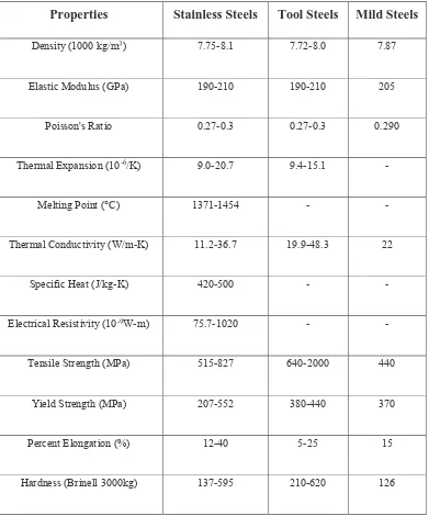
Table 2.1: Mechanical properties comparison for the selected materials.
Properties Stainless Steels Tool Steels Mild Steels
Density (1000 kg/m3) 7.75-8.1 7.72-8.0 7.87
Elastic Modulus (GPa) 190-210 190-210 205
Poisson's Ratio 0.27-0.3 0.27-0.3 0.290
Thermal Expansion (10-6/K) 9.0-20.7 9.4-15.1 -
Melting Point (°C) 1371-1454 - -
Thermal Conductivity (W/m-K) 11.2-36.7 19.9-48.3 22
Specific Heat (J/kg-K) 420-500 - -
Electrical Resistivity (10-9W-m) 75.7-1020 - -
Tensile Strength (MPa) 515-827 640-2000 440
Yield Strength (MPa) 207-552 380-440 370
Percent Elongation (%) 12-40 5-25 15
9
2.3 Surface Finish
Surface finish or also known as surface texture and thus coefficient of friction during sliding is influenced by the roughness parameters (Menezes, Kishore, & Kailas, 2008). Many attempts have been made to study the effect of surface texture on friction and wear during sliding conditions. The surface texture can be isotropic or anisotropic. Sometimes, stick-slip friction phenomenon can be observed while sliding depends on the texture surface. Surface finish also has an important effect on its corrosion resistance(Honess, 2006).
10
2.3.1 Friction
The understanding of friction phenomena is of most importance for designing and increasing the useful of machines lifetime. By referring to the flange resurface machine, the attachment between the adjustable jaw and pipe wall will resulting a sliding friction if the attachments is not rigid enough. Sliding friction is a complex process depending on several parameters such as the applied normal force, sliding velocity, material properties, dimensions of the slider and roughness of the contact surfaces, lubricated or dry conditions and thermal effects (Philippon, Sutter, & Molinari, 2004). Friction tests between a pair of sliding surfaces indicate that the dry friction coefficient are depends on the intrinsic characteristics of the interfaces tested for the ranges of parameters and conditions considered, and also on the dynamic properties of the device used such as mass, inertia, stiffness and damping.
11
2.3.2 Surface Finish Shape
a) One of the texturing technique used in sheet metal forming are electron beam texturing and laser texturing as shown below in Figure 2.3. The pattern can be produced with a focused beam that evaporates or ablates local spots on the surface resulting in circular crater-formed depressions (Co, 2014). The advantages of this pattern is increase the yield process and the productivity due to reduced press downtime and improved metal flow in the die, as strain that cause breakage are prevented. It has recently attracted a lot of interest in many different applications fields such as seals, bearing and hard disc.
Figure 2.3: A ball bearing steel surface treated with laser texturing.
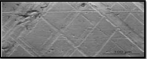
b) A well-established use of texturing for providing improve tribological properties is the honing of the cylinder surfaces use in combustion engines. The cylinder surfaces is treated with diamonds or stones to receive a cross-hatch pattern of fine score. The purpose of this pattern as in Figure 2.4 below is to retain oil and provide good piston ring lubrication. Otherwise, the engine might consume too much oil and never seal properly.
12
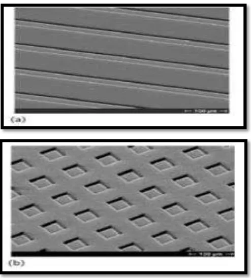
c) Silicon micromachining is an interesting alternatives for production of extremely well-controlled surface textures for fundamental studies. Wet etching is the process where material is removed by chemical reactions at the surface. The etching can be either isotropic or anisotropic. In isotropic etching the material is etched with the same rate in all direction, while in anisotropic etching the rate differs between different crystal planes. Etching of the silicon with potassium hydroxide was used as example, leaves the slowly etching planes as walls of texture depressions. Figure 2.5 below is the example of silicon surface with anisotropically.
Figure 2.5: Silicon surfaces with anisotropically etched surface textures. (a) Grooves