S
TRESS
!
Stress
!
Average Normal Stress in an Axially Loaded
Bar
!
Average Shear Stress
!
Allowable Stress
Equilibrium of a Deformable Body
A
D
w(s) C
FR
.
w
s
• Body Force
• Support Reaction
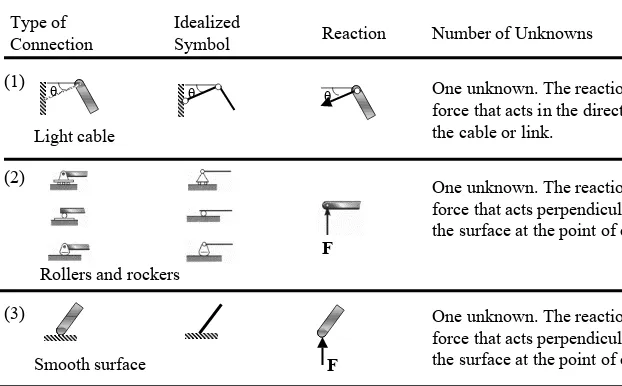
DyType of Connection
Idealized
[image:3.842.83.705.76.462.2]Symbol Reaction Number of Unknowns Table 1 Supports for Coplanar Structures
(1) θ
Light cable
One unknown. The reaction is a force that acts in the direction of the cable or link.
θ θ
One unknown. The reaction is a force that acts perpendicular to the surface at the point of contact. F
Rollers and rockers (2)
One unknown. The reaction is a force that acts perpendicular to the surface at the point of contact. (3)
Type of Connection
Idealized
Symbol Reaction Number of Unknowns
Three unknowns. The reactions are the moment and the two force components.
M Fy Fx
(6)
Fixed support
Two unknowns. The reactions are two force components. Fy
Fx (4)
Smooth pin or hinge
Two unknowns. The reactions are a force and moment.
(5)
Internal pin
• Equation of Equilibrium
Σ
Σ
Σ
Σ F = 0
Σ
Σ
Σ
Σ M
O= 0
Σ
Σ
Σ
Σ F
x= 0
Σ
Σ
Σ F
Σ
y= 0
Σ
Σ
Σ F
Σ
z= 0
Σ
Σ
Σ
• Internal Resultant Loadings
F
2F
1F
3F
4section
F
2F
1x
y
F
3F
4V
N
M
OV
N
Example 1
Determine the resultant internal loadings acting on the cross section at C of the beam shown.
270 N/m
3 m 6 m
A B
• Support Reactions
(1/2)(9)(270) = 1215 N
3 m 6 m
A
B C
270 N/m
540 N
4 m
B
2 m 180 N/m
C
540 N =
V
CN
CM
C0 = -540(2) = -1080 N•m =
540 N 135 N
90 N/m
MA = 3645 N•m
3 m
A C
A = 1215 N 270 N/m
180 N/m
540 N
1080 N•m
0
• Internal Loading
MA = 3645 N•m
9
bh tw
(1/2)(9)(270) = 1215 N
3 m 6 m
A
B C
270 N/m
• Shear and bending moment diagram
3645 N•m
1215 N
V (N) 1215
M (N•m)
+
3645
-540
1080
1080 N•m
C
540 N
web flanges
Example 2
Determine the resultant internal loadings acting on the cross section at C of the machine shaft shown. The shaft is supported by bearings at A and B, which exert only vertical forces on the shaft.
225 N 800 N/m
200 mm
50 mm
100 mm 100 mm
50 mm A
C
B
11
(800 N/m)(0.15 m) = 120 N/m 225 N0.275 m 0.125 0.1 m
A B
D • Support Reactions
0.2 m
0.025 m A
C
800(0.05) = 40 N
18.75 N
VC MC
NC • Internal Loading
+ Σ M
A = 0: -(120)(0.275) + By(0.4) - (225)(0.5) = 0, By = 363.75 N
+ ΣM
A = 0:
18.75(0.25) + 40(0.025) + MC = 0 M = -5.69 N•m ΣFx = 0: NC = 0
+
ΣFy = 0:
-18.75 - 40 - VC = 0,
VC = -58.75 N
+
Σ Fy = 0: Ay - 120 +363.75 - 225 = 0 Ay = -18.75 N,
+
By Ay
Ax
Σ Fx = 0: Ax = 0 Ax = 0,
58.75 N 5.69 N•m
0
0.2 m
0.025 m A
C
800(0.05) = 40 N
18.75 N
VC = -58.75 N
MC = -5.69 N•m
NC = 0
0.2 m
0.025 m A
C
800(0.05) = 40 N
18.75 N
Example 3
The hoist consists of the beam AB and attached pulleys, the cable, and the motor. Determine the resultant internal loadings acting on the cross section at C if the motor is lifting the 2 kN load W with constant velocity. Neglect the weight of the pulleys and beam.
1 m 2 m 0.5 m
W 0.15 m
0.15 m C
A D
1 m 2 m 0.5 m
W 0.15 m
0.15 m C
A D
B
W = 2 kN
1 m 0.15 m
C A
W = 2 kN
VC MC NC TC = 2 kN
+ Σ M
C = 0:
MC - 2(0.15) + 2(1.15) = 0
MC = -2 kN•m Σ Fx = 0:
2 + NC = 0 NC = -2 kN
+
Σ Fy = 0:
-2 - VC = 0, VC = -2 kN
Example 4
Determine the resultant internal loadings acting on the cross section at G of the wooden beam shown . Assume the joints at A, B, C, D, and E are pin-connected.
6.5 kN
0.6 m 0.6 m 2 m
1 m
A
B C
D
E G
6.5 kN
0.6 m 0.6 m (2/3)(2) = 4/3 m
1 m
A
B C
D
E G
4 kN/m (1/2)(2)(4) = 4 kN
2/3 m
FBC
Ex Ey • Support Reactions
+ Σ M
E = 0: 4(4/3) + 6.5(3.2) - FBC(1) = 0, FBC = 26.1 kN
Σ Fy = 0: -6.5 - 4 + Ey = 0 Ey = 10.5 kN
+
Two - force
Σ Fx = 0: 26.13 + Ex = 0 Ex = -26.1 kN,
• Internal loadings acting on the cross section at G
+ ΣM
G = 0: MG -34.02 sin39.81o(0.6) + 6.5(0.6) = 0 MG = 9.17 kN•m
ΣFy = 0: -6.5 + 34.02 sin39.81o - V
G = 0 VG = 15.3 kN
+
ΣFx = 0: 34.02 cos39.81o + N
G = 0 NG = -26.1 kN
+
VC
MC NC 0.6 m
6.5 kN
A
G
B
FBC = 26.13 kN
50.19o
39.81o
FBD FBA
FAB
Joint B ΣFx = 0:
-FBA sin50.19o + 26.13 = 0
FBA = 34.0 kN, (T)
+
ΣFy = 0:
-FBA cos50.19o -F
BD = 0
FBD = -21.8 kN, (C)
+
= -21.78 kN 34.02 kN =
= 34.02 kN
Example 5
Determine the resultant internal loadings acting on the cross section at B of the pipe shown. The pipe has a mass of 2 kg/m and is subjected to both a vertical force of 50 N and a couple moment of 70 N•m at its end A. It is fixed to the wall at C.
50 N
1.25 m 0.75 m
0.5 m
70 N•m A
B C
D x
(MB)y
50 N
70 N•m A
B
D
x y
z
(FB)y (FB)x
(FB)z
0.25 m
WBD= 9.81 N W
BD = (2 kg/m)(0.5 m)(9.81 N/kg) = 9.81 N
0.625 m
0.625 m WAD
WAD = (2 kg/m)(1.25 m)(9.81 N/kg) = 24.52 N
• Free-Body Diagram
• Equilibrium of Equilibrium
Σ
Fy = 0: (FB)y = 0Σ
Fz = 0: (FB)z - 9.81 -24.525 -50 = 0, (FB)z = 84.3 NΣ
(MB)x = 0: (MB)x + 70 - 50(0.5) - 24.525(0.5) - 9.81(0.25) = 0, (MB)x = -30.3 N•mΣ
(MB)y = 0: (MB)y + 24.525(0.625) + 50(1.25) = 0, (MB)y = -77.8 N•mΣ
(MB)x = 0: (MB)z = 0(MB)x
(MB)z
(MB)y
(MB)x
(MB)z
Σ
Fx = 0: (FB)x = 0• Free-Body Diagram
50 N
70 N•m A
B
D
x y
z
0.25 m 9.81 N
0.625 m
0.625 m 24.5 N
70 N•m
(FB)x = 0
(FB)y = 0
(FB)z = 84.3 N
(MB)x = -30.3 N•m
(MB)y = -77.8 N•m
(MB)z = 0
84.3 N
30.3 N•m
+
z
Face
+
x
Face
x
y
z
Stress
22
x
y
z
-
x
Face
τ
yzτ
yxσ
yτ
zyτ
zxσ
zσ
'
xτ
'
xzτ
'
xy-
y
Face
σ
'
yτ
'
yzτ
'
yx-
z
Face
τ
'
zyτ
'
zxσ
'
zx
y
Top View
τ
xy∆
y
∆
z
σ
x∆
y
∆
z
τ
yx∆
x
∆
z
σ
y∆
x
∆
z
σ'
x∆
y
∆
z
τ'
xy∆
y
∆
z
σ'
y∆
x
∆
z
τ'
yx∆
x
∆
z
σ
x=
σ
'
x
σ
y=
σ
'
y
σ
z=
σ
’
z
τ
xy=
τ
'
xy
τ
yx=
τ
'
yx
τ
zx=
τ
’
xz
By compatibility,
τ
xzτ
xyΣFy = 0: - σ'y
∆
x
∆
z +
σ
y∆
x
∆
z
= 0
+
σ'
y=
σ
yΣFx = 0:
σ
x∆
y
∆
z -
σ'
x∆
y
∆
z
= 0
+
σ
x=
σ'
x+ ΣM
O´ = 0: (τxy
∆
y
∆
z
)(∆
x
) - (τ
yx∆
x
∆
z
)(∆
y
) = 0
τ
xy= τ
yxx
y
τ
xy∆
y
∆
z
σ
x∆
y
∆
z
τ
yx∆
x
∆
z
σ
y∆
x
∆
z
σ'
x∆
y
∆
z
τ'
xy∆
y
∆
z
σ'
y∆
x
∆
z
τ'
yx∆
x
∆
z
O
σ
x∆
y
∆
z
σ'
x∆
y
∆
z
τ
xy∆
y
∆
z
τ'
xy∆
y
∆
z
σ
y∆
x
∆
z
σ'
y∆
x
∆
z
τ
yx∆
x
∆
z
τ'
yx∆
x
∆
z
z
x
y
∆
x
∆
y
τ
yz∆
x
∆
z
σ
y∆
x
∆
z
τ
yx∆
x
∆
z
σ
z∆
x
∆
y
τ
zy
∆
x
∆
y
τ
zx∆
x
∆
y
∆
z
τ
xz∆
y
∆
z
τ
xy∆
y
∆
z
σ
x∆
y
∆
z
σ
'
z∆
x
∆
y
σ
'
x∆
y
∆
z
σ
'
y∆
x
∆
z
z
x
y
σ
y∆
x
∆
z
σ
z∆
x
∆
y
σ
x∆
y
∆
z
z
x
y
τ
zx∆
x
∆
y
τ
xz∆
y
∆
z
τ
'
xz∆
y
∆
z
τ
'
zx∆
x
∆
y
z
x
y
τ
yz∆
x
∆
z
τ
zy∆
x
∆
y
τ
'
yz∆
x
∆
z
τ
'
zy∆
x
∆
y
z
x
y
τ
xy∆
y
∆
z
τ
yx∆
x
∆
z
τ
'
yx∆
x
∆
z
Average Normal Stress in an Axially Loaded Bar
• Assumptions
The material must be
- Homogeneous material
- Isotropic material
P
P
P
External force
Internal force
P
P x
y z
P
x
y
σ
∆F = σ∆A
P
σ σ
∫
=∫
Σ = ↑
+
A z
Rz F dF dA
F ;
σ
A P =
σ
A P =
σ
Example 6
The bar shown has a constant width of 35 mm and a thickness of 10 mm.
Determine the maximum average normal stress in the bar when it is subjected to the loading shown.
9 kN
9 kN
4 kN
4 kN
A B C D
35 mm
9 kN
9 kN
4 kN
4 kN
A B C D
35 mm
22 kN 12 kN
12
22 30
P (kN)
x
10 mm
35 mm
30 kN
σ
MPa 7
. 85 )
m 01 . 0 )( m 035 . 0 (
kN 30
max = = = =
A P
σ
σ BC
9 kN
9 kN
4 kN
4 kN
A B C D
35 mm
22 kN 12 kN
34.3
62.9 85.7
σ
(MPa)x
10 mm
35 mm
30 kN
σ
MPa 7
. 85 )
m 01 . 0 )( m 035 . 0 (
kN 30
max = = = =
A P
σ
σ BC
Example 7
The 80 kg lamp is supported b two rods AB and BC as shown . If AB has a diameter of 10 mm and BC has a diameter of 8 mm, determine which rod is subjected to the greater average normal stress.
60o
A
B
C
B
x y
• Internal Loading
0 60 cos ) 5 4 ( ;
0 − =
= Σ →
+ o
BA BC
x F F
F 0 8 . 784 60 sin ) 5 3 ( ;
0 + − =
= Σ ↑ + o BA BC
y F F
F
FBC = 395.2 N, FBA = 632.4 N
• Average Normal Stress
60o A B C 3 4 5 d = 10 mm
d = 8 mm
MPa 86 . 7 ) m 004 . 0 ( N 2 . 395 2 = = = π A F σ BC BC BC MPa 05 . 8 ) m 005 . 0 ( N 4 . 632 2 = = = π A F σ BA BA BA
The average normal stress distribution acting over a cross section of rod AB.
632.4 N 8.05 MPa 8.05 MPa 8.05 MPa 60o FBA 3 4 5 FBC
Example 8
Member AC shown is subjected to a vertical force of 3 kN. Determine the
position x of this force so that the average compressive stress at C is equal to the average tensile stress in the tie rod AB. The rod has a cross-sectional area of 400 mm2 and the contact area at C is 650 mm2.
200 mm 3 kN
A B
200 mm 3 kN
A
C x
FAB
FC ) 1 ( 0
3 ;
0 + − = −−−−
= Σ ↑
+ Fy FAB FC
+ Σ M
A = 0: -3(x) + FC(200) = 0 ---(2)
• Internal Loading
• Average Normal Stress
650 400
C
AB F
F = =
σ
) 3 ( 625
.
1 −−−−
= AB
C F
F
Substituting (3) into (1), solving for FAB, the solving for FC, we obtain
V
V
P
Connections
P
A
B
C
D
ττττ
avgA V
avg =
τ
P
A
A
V
• Single Shear
P
P
P
V = P
P
P
Top View
P
P
Side View
P
P
P
V = P
P
P
Top View
P
P
• Double Shear
P
P
Top View
P
/2
P
P
/2
P
P
Side View
V = P/2
P
V = P/2
P
P
Top View
P
/2
P
P
/2
P
P
Side View
V = P/2
P
Normal Stress: Compression and Tension Load
P
P
P
P´
b
d t a
a b
b
bt P
a a− = @
σ
b
t
A
=
bt
P
Section a-a
t d b
P
b b
) (
@
− =
−
σ
b
t
d
A = (b-d)t
P
t
b
d
P
P
b´
b´
t
d Abearing = dt
Bearing Stress
dt P
bearing =
σ
P/2
P/2
P
39
dθd b
t t
d b
P
normal
) ( − =
σ
ΣFx = 0:
+ ) cos 0
2 (
90
90 =
−
∫
°°
−
σ
tθ
dθ
d
P b
P d
t d
b =
°
° − 90
90
sin )
2
(
σ
θ
θ
o bearing
td P
90 sin =
σ
* − − − − − = P
bearing
σ
θ
dt P
bearing =
P
d
P
b
t
Tension
Compression
• Axial Force Diagram for Compression Load on Plate
-P
-P
dt P Stress
Bearing bearing =
−
σ
n compressio t
bd P Stress
Normal ,
) (
: = −
41
b
t
Tension
Compression
• Axial Force Diagram for Tension Load on Plate
tension t
d b
P Stress
Normal ,
) (
max :
− + =
−
σ
at P Stress
Shearing
2 =
−
τ
dt P Stress
Bearing bearing =
−
σ
P
P
d
P
a
P/2
P/2
t
a
P
P
τ
• Shearing Stress on pin
P
P
P
P
P
P
P
P
P
P
P
P
A P =
τ
Double Shear
P/
2
P
P/
2
P
/2
P
P
/2
P/
2
P/
2
P
P/
2
P/2
P/
2
P/2
P
P/2
P/2
P/
2
P/
2
P
A P
τ = / 2
A P
z
x
y
∆
y
∆
x
∆
z
Section plane
Pure shear
τ
yzτ
zyτ
yzτ
zyPure Shear
Example 9
The bar shown a square cross section for which the depth and thickness are 40 mm. If an axial force of 800 N is applied along the centroidal axis of the bar’s cross-sectional area, determine the average normal stress and average shear stress acting on the material along (a) section plane a-a and (b) section plane b-b.
800 N
a
a
b
b
30o
N = 800 N
(a) section plane a-a
800 N
a
a
kPa 500 )
m 04 . 0 )( m 04 . 0 (
N 800
= =
= A N
σ
0 =
avg
τ
500 kPa 800 N
a
a
b
b
30o
(b) section plane b-b 800 N b b 30o 800 N 30o
N = 800sin30o = 400 N V = 800 cos30o = 692.82 N
kPa 125 ) m 08 . 0 )( m 04 . 0 ( N 400 = = = A N σ kPa 51 . 216 ) m 08 . 0 )( m 04 . 0 ( N 82 . 692 = = = A V τ avg 30o x 40 mm mm 80 ; 40 30
sin = x =
Example 10
The wooden strut shown is suspended form a 10 mm diameter steel rod, which is fastened to the wall. If the strut supports a vertical load of 5 kN, compute the average shear stress in the rod at the wall and along the two shaded planes of the strut, one of which is indicated as abcd.
5 kN a b
c
d
20 mm
5 kN
63.7 MPa
V = 5 kN
• Average shear stress in the rod at the wall
5 kN
d = 10 mm
MPa 7 . 63 ) m 005 . 0 ( kN 5 2 = = = π A V τ avg
• Average shear stress along the two shaded plane
MPa 12 . 3 ) m 02 . 0 )( m 04 . 0 ( kN 5 . 2 = = = A V τ avg 5 kN 3.12 MPa 5 kN a b c d 20 mm 40 mm
V = 2.5 kN
a b
c
d
5 kN
Example 11
The inclined member show is subjected to a compressive force of 3 kN.
Determine the average compressive stress along the areas of contact defined by AB and BC, and the average shear stress along the horizontal plane defined by EDB.
25 mm
40 mm 80 mm 50 mm
3 kN 4
FBC= 3(4/5) = 2.4 kN V = 1.8 kN
1. 2 MPa
3 kN 4 5 3 3 kN 4 5 3 MPa 8 . 1 kPa 1800 ) m 040 . 0 )( m 025 . 0 ( kN 8 . 1 = = = = AB AB AB A F σ MPa 2 . 1 kPa 1200 ) m 040 . 0 )( m 050 . 0 ( kN 4 . 2 = = = = BC BC A F σ
• The average compressive stress along the areas of contact defined by AB and BC :
1.8 MPa
25 mm
40 mm 80 mm 50 mm
3 kN 4
5 3
V = 1.8 kN
FBC= 3(4/5) = 2.4 kN
3 kN
4 5
3
FAB = 3(3/5) = 1.8 kN
• The average shear stress along the horizontal plane defined by EDB :
25 mm
40 mm 80 mm 50 mm
3 kN 4
5 3
MPa 562
. 0
kPa 5 . 562 )
m 08 . 0 )( m 04 . 0 (
kN 8 . 1
=
= =
= A V
τ avg
1.8 kN
Allowable Stress
allow fail
P P S
F. =
allow fail
S F
σ
σ
= .
allow fail
S F
τ
τ
= .
6. Design of Simple Connections
allow
P A
σ
=
allow
V A
τ
=
• Cross-Sectional Area of a Tension Member
P
P
a
a
P
τ
allowallow
P A
σ
(σ
b)
allowP
V = P
P
• Cross-Sectional Area of a Connector Subjected to Shear
allow
P A
σ
=
P
P
ττττ
allow• Required Area to Resist Bearing
allow b
P A
• Required Area to Resist Shear by Axial Load
P
d P l
allow
π
τ
=
P
d
Example 12a
The control arm is subjected to the loading shown. (a) Determine the shear stress for the steel at all pin (b) Determine normal stress in rod AB, plate D and E. The thickness of plate D and E is 10 mm.
pin C 13 kN 25 kN
3 4
5
75 mm 50 mm 200 mm
A B
C D E
φ
= 10 mmφ
= 20 mmD E
φ
= 25 mm13 kN 50 mm
25 kN 50 mm
25 kN 13 kN
3 4
5
75 mm 50 mm 200 mm
• Reaction C
0 ) 125 . 0 ( 87 . 36 sin 25 ) 075 . 0 ( 13 ) 2 . 0 ( + − = AB F + ΣM
C = 0:
FAB = 4.5 kN , ←
ΣFy = 0:
+ C
y + 13 - 25sin36.87o = 0 Cy = 2 kN, ↑ ΣFx = 0:
+
-4.5 - Cx + 25cos36.87o = 0
Cx = 15.5 kN, ←
kN 63 . 15 ) 2 ( ) 5 . 15
( 2 + 2 =
= C
25 kN 13 kN
25 kN 13 kN
75 mm 50 mm 200 mm
4.5 kN
(a) Shear stress
15.63 kN
15.63 kN
Pin C (Double shear)
7.815 kN
7.815 kN
Pin D and E (Single shear)
pin C 13 kN 25 kN
3 4
5
75 mm 50 mm 200 mm
A B
C D E
φ
= 35 mmφ
= 20 mmφ
= 25 mmφ
= 25 mm⇐ =
=
= 24.88 MPa
) 02 . 0 )( 4 / ( kN 815 . 7 2 π A V τ C C ⇐ = =
= 26.48 MPa
) 025 . 0 )( 4 / ( kN 13 2 π A V τ D D D ⇐ = =
= 50.93 MPa
59
25 kN 13 kN75 mm 50 mm 200 mm
4.5 kN
(b) Normal stress
15.63 kN
Cale AB Plate D
φ
rod = 10 mm AC D E σ ⇐ = =
= 56.7 MPa
) 010 . 0 )( 4 / ( kN 5 . 4 2
π
σ
AB AB A P D Eφ
= 25 mm13 kN 50 mm
25 kN 50 mm
φ = 25 mm
13 kN
σD 13 kN
13 kN
t = 0.01 m
25 kN 13 kN
75 mm 50 mm 200 mm
4.5 kN
15.63 kN
φ
rod = 35 mm AC
D E
Plate E
⇐ =
− =
=
MPa 100
) 01 . 0 )( 025 . 0 05 . 0 (
kN 25 A
P
E
σ
D E
φ
= 25 mm13 kN 50 mm
25 kN 50 mm
φ
= 25 mm25 kN 50 mm
25 kN
25 kN 50 mm
σE
0.05 m
0.02 5 m t = 0
Example 12b
The control arm is subjected to the loading shown. Determine the required diameter of the steel pin at C if the allowable shear stress for the steel is τallow = 55 MPa. Note in the figure that the pin is subjected to double shear.
22 kN 13 kN
3 4
5
75 mm 50 mm 200 mm
A B
• Internal Shear Force 0 ) 125 . 0 ( 87 . 36 sin 22 ) 075 . 0 ( 13 ) 2 . 0 ( − − = AB F + ΣM
C = 0:
FAB = 13.125 kN
ΣFy = 0:
+ C
y - 13 - 22sin36.87o = 0
Cy = 26.2 kN ΣFx = 0:
+
-13.125 - Cx + 22cos36.87o = 0
Cx = 4.47 kN
kN 58 . 26 ) 2 . 26 ( ) 47 . 4
( 2 + 2 =
= C
22 kN 13 kN
75 mm 50 mm 200 mm FAB Cy Cx 22 kN 13 kN 3 4 5
• Required Area
2 2
6 6
3
mm 242
m 10 6
. 241 10
55
10 29
. 13
= ×
= ×
× =
= −
allow τ
V A
2 2
mm 242
) 2
(d =
π
d = 17.55 mm
Use d = 20 mm 22 kN
13 kN 3
4 5
75 mm 50 mm 200 mm
A B
C
22 kN 13 kN
75 mm 50 mm 200 mm
13.125 kN
26.58 kN
26.58 kN
13.29 kN
Example 13a
The two members are pinned together at B as shown below. Top views of the pin connections at A and B are also given. If the pins have an allowable shear stress of
τ
allow = 86 MPa , the allowable tensile stress of rod CB is (σ
t)allow = 112 MPa and the allowable bearing stress is (σ
b)allow = 150 MPa, determine to the smallest diameter of pins A and B ,the diameter of rod CB and the thickness of ABnecessary to support the load.
13 kN
A
B
C
1 m 0.6 m
3 4 5 Top view
A
• Internal Force
13 kN
A B
FBC
1 m 0.6 m
36.87o
Ay
Ax
+ Σ M
A = 0: −13(1)+ FBC sin36.87(1.6) =0 FBC = 13.54 kN Σ Fy = 0:
+ Ay −13+13.54sin36.87 =0
Ay = 4.88 kN Σ Fx = 0:
+ − +13.54cos36.87 =0
x
A
• Diameter of the Pins
13 kN
A B
FBC = 13.54 kN
1 m 0.6 m
36.87o
Ay = 4.88 kN
Ax = 10.83 kN
Top view A B 11.88 kN Pin A 11.88 kN
VA = 5.94 kN
VA = 5.94 kN
2 2
3 69.07 mm
m / kN 10 86 kN 94 . 5 = × = = allow A A τ V A 2 2 mm 07 . 69 ) (
4 d A =
π
d = 9.38 mm, Use d = 10 mm
Pin B
FBC = 13.54 kN
VB= 13.54 kN
2 2
3 157.4 mm
m / kN 10 86 kN 54 . 13 = × = = allow B B V A
τ
2 2 mm 4 . 157 ) (4 dB =
π
• Diameter of Rod
13.54 kN
13.54 kN
2 2
3 120.9 mm
m / kN 10
112
kN 54 . 13 )
( = × =
=
allow t
BC
σ
P A
2 2
mm 9 . 120 )
(
4 dBC =
π
dBC = 12.4 mm, Use dBC = 15 mm 13 kN
A B
FBC = 13.54 kN
1 m 0.6 m
36.87o
Ay = 4.88 kN
tAB
φ
B = 15 mm 20 kNA B
13.54 kN 11.88 kN
tAB
φ
A = 10 mmA B
(
σ
b )A (σ
b )Bm 00792 . 0 ) 010 . 0 ( 10 88 . 11 10 150 ) ( 3 6 = × = × = AB AB allow b t t A P σ • Thickness 13 kN A B
FBC = 13.54 kN
1 m 0.6 m
36.87o
Ay = 4.88 kN
Example 13b
The two members are pinned together at B as shown below. Top views of the pin connections at A and B are also given. If the pins have an allowable shear stress of
τ
allow = 86 MPa, the allowable tensile stress of rod CB is (σ
t)allow = 112 MPa and the allowable bearing stress is (σ
b)allow = 150 MPa, determine to themaximum load P that the beam can supported.
P A
B
C
1 m 0.6 m
3 4 5 Top view
A
B
φ
= 15 mmφ
= 10 mmt = 8 mm
φ
= 15 mm• Internal Force
P
A B
FBC
1 m 0.6 m
36.87o
Ay
Ax
+ Σ M
A = 0: −P(1)+ FBC sin36.87(1.6) = 0
FBC = 1.042P (T) 0
87 . 36 sin 042
. 1 ;
0 − + =
= Σ ↑
+ Fy Ay P P
Ay = 0.375P 0
87 . 36 cos 042
. 1 ;
0 − + =
= Σ → +
P A
Fx x
Pin A (double shear) 0.914P
VA = 0.457P
VA = 0.457P
kN 78 . 14 ) 01 . 0 )( 4 / ( 457 . 0 kPa 10
86 3 2
= = × = P π P A V τ A A allow
Pin B (single shear)
FBC = 1.042P
VB= 1.042P
kN 58 . 14 ) 015 . 0 )( 4 / ( 042 . 1 kPa 10
86 3 2
= = × = P π P A V τ B B allow P A B
FBC = 1.042P
1 m 0.6 m
36.87o
Ay = 0.375P
0.834P
Top view A
B
0.914P
φ
= 10 mm1.042P
1.042P Rod AB
P
A B
FBC = 1.042P
1 m 0.6 m
36.87o
Ay = 0.375P
0.834P
0.914P
kN 19
) 015 . 0 )( 4 / (
042 . 1 kPa
10
112 3 2
= = ×
=
P
π
P A
P
σ
BC allow
tAB = 10 mm
φ
B = 15 mm 20 kNA B
FBC = 1.042P
0.914P
tAB = 10 mm
φ
A = 10 mmA B
(
σ
b )A (σ
b )BkN 41 . 16 ) 010 . 0 )( 010 . 0 ( 914 . 0 10 150 ) ( 6 = = × = P P A P σ allow b kN 60 . 21 ) 01 . 0 )( 015 . 0 ( 042 . 1 10 150 ) ( 6 = = × = P P A P σ allow b P A B
FBC = 1.042P
1 m 0.6 m
36.87o
Ay = 0.375P
0.834P
Top view A
B
0.914P
φ
= 10 mmφ
= 15 mmt = 10 mm
t = 10 mm
⇐ =14.58 kN P
Example 14
The suspender rod is supported at its end by a fixed-connected circular disk as shown. If the rod passes through a 40-mm diameter hole, determine the minimum required diameter of the rod and the minimum thickness of the disk needed to support the 20 kN load. The allowable normal stress for the rod is σallow = 60 MPa, and the allowable shear stress for the disk is τallow = 35 MPa.
d
40 mm t
20 kN 20 kN
40 mm
d
40 mm t
20 kN 20 kN
40 mm
τallow
• Diameter of Rod
2 3 m / kN 10 60 kN 20 × = = allow σ P A 2 3 2 m / kN 10 60 kN 20
4 = ×
= π d A
d = 0.0206 m = 20.6 mm
• Thickness of Disk
2 3 m / kN 10 35 kN 20 × = = allow τ V A 2 3 m / kN 10 35 kN 20 ) m 02 . 0 ( 2 × = t π
Example 15
An axial load on the shaft shown is resisted by the collar at C, which is attached to the shaft and located on the right side of the bearing at B. Determine the largest value of P for the two axial forces at E and F so that the stress in the collar does not exceed an allowable bearing stress at C of (σb)allow = 75 MPa and allowable shearing stress of the adhesive at C of τallow = 100 MPa , and the average normal stress in the shaft does not exceed an allowable tensile stress of (σt)allow = 55 MPa.
A B
P
C E
F 2P
60 mm 20 mm
A B P C E F 2P
60 mm 20 mm
80 mm 3P Position Load 3P 2P
• Axial Stress
3P P 2P A P allow
t) =
(
σ
2 2 3 ) m 03 . 0 ( 3 m / kN 10 55 π P = ×P1 = 51.8 kN
• Bearing Stress
A P
allow
b) =
(
σ
] ) m 03 . 0 ( ) m 04 . 0 ( [ 3 m / kN 1075 3 2 2 2
π π P − = × B C 60 mm 80 mm 3P
A B P
C E
F 2P
60 mm 20 mm
80 mm 3P
Position Load
3P 2P
The largest load that can be applied to the shaft is P = 51.8 kN.
shear allow
A P =
τ
)] 020 )(. m 04 . 0 ( 2 [
3 m
/ kN 10
100 3 2
π
P =
×
P3 = 55 kN • Shearing Stress
B
C
60 mm
80 mm 3P
20 mm
• Axial Stress
• Shearing Stress • Bearing Stress
P3 = 55 kN P1 = 51.8 kN
Example 16
The rigid bar AB shown supported by a steel rod AC having a diameter of 20 mm and an aluminum block having a cross-sectional area of 1800 mm2 .
The18-mm-diameter pins at A and C are subjected to single shear. If the failure stress for the steel and aluminum is (σst)fail = 680 Mpa and (σal)fail = 70 MPa, respectively, and the failure shear stress for each pin is τfail = 900 MPa, determine the largest load P that can be applied to the bar. Apply a factor of safety of F.S = 2.0.
P Steel
0.75 m
2 m
Aluminum
A B
+ ΣM
B = 0: P(1.25 m) - FAC(2 m) = 0 ---> FAC = 0.625P 1.25 m P A B FAC FB 0.75 m + ΣM
A = 0: P(0.75 m) - FB(2 m) = 0 ---> FB = 0.375P P Steel 0.75 m 2 m Aluminum A B C
• Rod AC
AC AC fail st allow st A F S F = = . ) ( ) (
σ
σ
2 3 m) π(0.01 0.625 2 kPa 10 680 P = ×P1 = 171 kN
• Block B
B B fail al allow al A F S F = = . ) ( ) (
σ
σ
2 6 3 m 10 1800 0.375 2 kPa 10 70 − × = × PP Steel
0.75 m
2 m
Aluminum
A B
C
• Pin A or C
pin AC fail
allow
A F S
F =
= .
τ
τ
2 3
m)
π(0.009
0.625 2
kPa 10
900 P
= ×
P3 = 183 kN
Largest load P = 168 kN
1.25 m P
A B
FAC= 0.625P
FB= 0.375P 0.75 m
• Pin A or C P3 = 183 kN Summary
• Rod AC P1 = 171 kN
STRAIN
!
Deformation
!
Strain
!
Normal Strain
!
Shear Strain
Deformation
Deformed body
θ
A B C
Undeformed body u(A)
A´
B´ C´
Strain
x y
z
x y
z
x y
1 εx 1
x y
1
1
εy
x y
x y
2
π x
y
xy
γ
xy
γ
εy
1
1 εx
Example 1
The slender rod shown subjected to an increase of temperature along its axis, which creates a normal strain in the rod of
ε
z = 40(10-3)z1/2, where z is given in meters. Determine (a) the displacement of the end B of the rod due to thetemperature increase, and (b) the average normal strain in the rod.
200 mm z
dz
A
200 mm z
dz
A
B
(a) the displacement of the end B of the rod due to the temperature increase
dz z
dz'=[40(10−3) 1/2]
∫
−=
∆ 0.2m
0 2 / 1 3 ] ) 10 ( 40
[ z dz
B
↓ =
= −
m z ) 0.00239 3 2 )( 10 ( 40 m 2 . 0 0 2 / 3 3
(b) the average normal strain in the rod.
Example 2
A force acting on the grip of the lever arm shown causes the arm to rotate clockwise through an angle of θ = 0.002 rad. Determine the average normal strain developed in the wire BC.
B
A
L 2L
B
A
L 2L
C B´
2L
B
A
L 2L
C
Lcos
θ
Lsin θθ
• Solution
001 . 0 2
002 . 0 2 2
'
= =
= =
−
=
θ
θ
ε
L L CB
CB CB
avg
Since θ is small, the stretch in wire CB, is using Eq.2-6. The average normal strain in the wire is then
, sinθ Lθ
Example 3
The plate is deformed into the dashed shape shown. If in this deformed shape horizontal lines on the plate remain horizontal and do not change their length, determine (a) the average normal strain along the side AB, and (b) the average shear strain in the plate relative to the x and y axes.
250 mm
300 mm
3 mm
2 mm B
C x
y
250 mm 3 mm 2 mm B y A B´ mm 018 . 248 ) 3 ( ) 2 250 (
'= − 2 + 2 = AB
(a) the average normal strain along the side AB
250 250 018 . 248 ' ) ( = − = − AB AB AB avg AB
ε
mm/mm ) 10 ( 93 .7 −3
− =
(b) the average shear strain in the plate relative to the x and y axes.
250 mm
300 mm 3 mm
2 mmB
C x y A B´
γ
xy θ´ rad 0121 . 0 ) 2 250 3 (tan 1 =
Example 4
The plate shown is held in the rigid horizontal guides at its top and bottom, AD and BC. If its right side CD is given a uniform horizontal displacement of 2 mm, determine (a) the average normal strain along the diagonal AC, and (b) the shear strain at E relative to the x, y axes.
150 mm
150 mm A
B C
D
E
A B 75 mm C´ D´ E´ 75 mm
76 mm 76 mm
(a) the average normal strain along the diagonal AC
m 21213 . 0 ) 150 . 0 ( ) 150 . 0
( 2 + 2 =
= AC m 21355 . 0 ) 152 . 0 ( ) 150 . 0 (
'= 2 + 2 =
A
B 75 mm
C´ D´
E´ 75 mm
76 mm 76 mm
θ
´(b) the shear strain at E relative to the x, y axes.
75 76 )
2 ' tan(
θ
= 150 mm150 mm A
B C
D
E
2 mm x y
rad 58404 .
1 ) 759 . 90 ( 180 759
. 90
'= o = π o o =
θ
rad 0132 .
0 58404
. 1
2 − = −
= π
1
M
ECHANICAL
P
ROPERTIES OF
M
ATERIALS
!
Simple Tension Test
!
The Stress-Strain Diagram
!
Stress-Strain Behavior of Ductile and Brittle
Materials
!
Hooke’s Law
!
Strain Energy
!
Poisson’s Ratio
!
The Shear Stress-Strain Diagram
2
400
350
300
250
200
150
100
50
0
εεεε
(mm/mm)
σ
σ
σ
σ
(MPa)
0.10 0.20 0.30 0.40 Upper scale
0.00
0.0020 0.0030
0.0010 0.0040 Lower scale
0.0000
Stress Strain Relationship
L0 d0
3
necking
strain
hardening
yielding
elastic
region
The Stress-Strain Diagram
εεεε
σ
σ
σ
σ
σ
plproportional limit
elastic limit
σ
fσ
uσ
f ´fracture stress
ultimate stress
elastic
behavior
plastic behavior
true fracture stress
yield stress
4
σY
0.002 (0.2% offset) 300
250
200
150
100
50
0
ε
(mm/mm)
σ
(MPa)
0.005 0.010
5
(
σ
y)u= 230 MPa(
σ
y)l= 220 MPa0
A P =
σ
0
L
δ
ε
=400
350
300
250
200
150
100
50
0
ε
(mm/mm)
σ
(MPa)
0.10 0.20 0.30 0.40 Upper scale
0.00
0.0020 0.0030
0.0010 0.0040 Lower scale
0.0000
E = = 200x103 MPa= 200 GPa
0.001
σ
fail = 295 MPaσpl = 200 MPa
σ
u = 390 MPa200
L0 d0
6
400
350
300
250
200
150
100
50
0
ε
(mm/mm)
σ
(MPa)
0.10 0.20 0.30 0.40 Upper scale
0.00
0.0020 0.0030
0.0010 0.0040 Lower scale
0.0000
σ
pl= 180 MPaσ
y= 250 MPaσ
u= 360 MPaσ
fail= 310 MPaE = = 200x103 MPa = 200 GPa
7
Stress-Strain Behavior of Ductile and Brittle Materials
0.02 0.04 0.06
100 200 300 400
σ (MPa)
ε (mm/mm)
σ−ε
σ−ε
σ−ε
σ−ε
diagrams for a methacrylate plastic Brittle material8
• Elongation
%) 100 ( 0
0
L L L
elongation
Percent = f −
%) 100 ( 0 0
A A A
area of
reduction
9
• Temperature Effects:
0.02 0.04 0.06
100 200 300 400
σ (MPa)
ε (mm/mm)
σ−ε σ−ε σ−ε
σ−ε diagrams for a methacrylate plastic
10 oC
40 oC
70 oC
10
σ
ε
Hooke’s Lawσ
plε
pl= =
pl pl E
ε
σ
11
- Apply load to failure
• Elastic and Plastic Behavior of Materials
1
σ
ε
PLEL
12
- Apply and release load
σ
ε
PLEL
(a) Load is less than proportional limit
1
2
σ
ε
PLEL
(b) Load is more than proportional limit, but less than elastic limit
1
13
2
3
1
2
3
4
Mechanical
hysteresis
1
σ
ε
PLEL
(c) Load is more than elastic limit, and reaply
σ
ε
PLEL
14
2
σ
ε
PLEL
Repeated loading
3
4
mechanical
hysteresis
1
σ
εεεε
O
1
15
E
E
elastic
region
plastic
region
O´
unload
ε
σ
A
O
load
A´
B
permanent
set
elastic
region
plastic
region
elastic
recovery
ε
σ
O´
A´
16
u
tu
rStrain Energy
• Modulus of Resilience
σ
plε
plε
σ
Modulus of resilience
u
r• Modulus of Toughness
ε
σ
Modulus of toughness
u
tE pl ur pl pl
2
2 1 2
1
σ
ε
σ
=17
Modulus of resiliency(ur)= Area under curve @ proportional limit
ur= (1/2)(0.001)(180 MPa) = 90 kPa = 90 kN/m2 = 90 kN•m/m3 = 90 kJ/m3
Upper scale
Lower scale
400350
300
250
200
150
100
50
0
ε
(mm/mm)
σ
(MPa)
0.10 0.20 0.30 0.40
0.00
0.0020 0.0030
0.0010 0.0040
0.0000
Energy per unit volume = (90 kN/m2)(1 m3) = 90 kN•m = 90 kJ
σ σσ
σpl= 180 MPa
18
400
350
300
250
200
150
100
50
0
ε
(mm/mm)
σ
(MPa)
0.10 0.20 0.30 0.40
0.00
0.0020 0.0030 0.0010
Upper scale
Lower scale
0.00400.0000
Modulus of hyper-resiliency EL
2
1
19
400
350
300
250
200
150
100
50
0
εεεε
(mm/mm)
σ
σ
σ
σ
(MPa)
0.10 0.20 0.30 0.40 Upper scale 0.00
0.0020 0.0030
0.0010 0.0040
Lower scale
0.0000
Failure
20
Example 1
A tension test for a steel alloy results in the stress-strain diagram shown.
Calculate the modulus of elasticity and the yield strength based on a 0.2% offset. Identify on the graph the proportional limit, elastic limit, ultimate stress and the fracture stress.
400
350
300
250
200
150
100
50
0
ε
(mm/mm)
σ
(MPa)
0.10 0.20 0.30 0.40 Upper scale
0.00
0.0020 0.0030
0.0010 0.0040 Lower scale
21
400
350
300
250
200
150
100
50
0
ε
(mm/mm)
σ
(MPa)
0.10 0.20 0.30 0.40 Upper scale
0.00
0.0020 0.0030
0.0010 0.0040 Lower scale
0.0000
σ σ σ σy
E
• Modulus of Elasticity
GPa mm
mm MPa
E 200
/ 0005
. 0
100
= =
• Yield Strength
σy = 250 MPa
σ σ σ
σpl • Proportional Limit
σpl = 180 MPa
σ σ σ σEL
• Elastic Limit
σ
pl = 220 MPaσ σσ σu
• Ultimate Stress
σ
u = 365 MPa• Fracture Stress
σ
= 310 MPa22
Example 2
An aluminum specimen shown has a diameter of d0 = 25 mm, a gauge length of L0 = 250 mm and is subjected to an axial load of 294.5 kN. If a portion of the stress-strain diagram for the material is shown, determine the approximate elongation of the rod when the load is applied. If the load is removed, does the rod return to its original length? Also, compute the modulus of resilience both before and after the load application.
0.01 0.02 0.04
150 300 450
σ (MPa)
ε (mm/mm)
0.03750
600
L0 d0
23
0.01 0.02 0.04
150 300 450
σ (MPa)
ε (mm/mm)
0.03750
600
F
O
294.5 kN 294.5 kN
L0 = 250 mm
294.5 kN 294.5 kN
L0 = 250 mm
d0 = 25 mm • The Load is Applied
- Normal Stress
MPa m
N A
P
600 )
025 . 0 )( 4 / (
10 5 . 294
2 3
0
= ×
= =
π
σ
- The Strain
ε
= 0.023 mm/mm- The Elongation
δ
=ε
L = (0.023 mm/mm)(250 mm) = 5.75 mmD
0.023
(5.75 mm)/2 (5.75 mm)/2
A
24
294.5 kN 294.5 kN
• The Load is Removed
0.01 0.02 0.04
150 300 450
σ (MPa)
ε (mm/mm)
0.03 750 600 F O D 0.023 A BL0 = 250 mm
d0 = 25 mm
- Permanent Strain
CD MPa GPa mm mm MPa
E 75.0 600
/ 006 . 0 450 = = =
CD = 0.008 mm/mm
The permanent strain, εOC = 0.023 - CD
εOC = 0.023 - 0.008 = 0.015 mm/mm - Normal Stress
MPa m N A P 600 ) 025 . 0 )( 4 / ( 10 5 . 294 2 3 0 = × = =
π
σ
- The Permanent Elongation
δ
=ε
L = (0.015 mm/mm)(250 mm) = 3.75 mmεpl=0.006
εOC
σpl =
E CDE C
294.5 kN 294.5 kN
L = 250 mm
25
(ur)initial
(ur)final
0.01 0.02 0.04
150 300 450
σ (MPa)
ε (mm/mm)
0.03 750 600 F O D 0.023 A BL0 = 250 mm
d0 = 25 mm
294.5 kN 294.5 kN
- Normal Stress
MPa m N A P 600 ) 025 . 0 )( 4 / ( 10 5 . 294 2 3 0 = × = =
π
σ
εpl=0.006
σpl =
CD = 0.008
C
• Modulus of Resilience
- Modulus of Resilience
3 / 40 . 2 ) / 008 . 0 )( 600 ( 2 1 2 1 ) ( m MJ mm mm MPa ur final pl pl
= = =
σ
ε
3 / 35 . 1 ) / 006 . 0 )( 450 ( 2 1 2 1 ) ( m MJ mm mm MPa ur initial pl pl= =