EXPLORING REGULARITIES FOR IMPROVING FAÇADE RECONSTRUCTION
FROM POINT CLOUDS
K. Zhou a, B. Gorte a, *, S. Zlatanova b
a
Dept. of Geoscience and Remote Sensing, TU Delft, the Netherlands-{k.zhou-1, b.g.h.gorte }@tudelft.nl b
Dept. of Urbanism, 3D Geoinformation, TU Delft, the Netherlands- [email protected]
Commission V, WG V/4
KEY WORDS: Terrestrial LiDAR point clouds, Regularities, Windows, Features, Hierarchical clustering, ICP, Chain
ABSTRACT:
(Semi)-automatic facade reconstruction from terrestrial LiDAR point clouds is often affected by both quality of point cloud itself and imperfectness of object recognition algorithms. In this paper, we employ regularities, which exist on façades, to mitigate these problems. For example, doors, windows and balconies often have orthogonal and parallel boundaries. Many windows are constructed with the same shape. They may be arranged at the same lines and distance intervals, so do different windows. By identifying regularities among objects with relatively poor quality, these can be applied to calibrate the objects and improve their quality. The paper focuses on the regularities among the windows, which is the majority of objects on the wall. Regularities are classified into three categories: within an individual window, among similar windows and among different windows. Nine cases are specified as a reference for exploration. A hierarchical clustering method is employed to identify and apply regularities in a feature space, where regularities can be identified from clusters. To find the corresponding features in the nine cases of regularities, two phases are distinguished for similar and different windows. In the first phase, ICP (iterative closest points) is used to identify groups of similar windows. The registered points and a number of transformation matrices are used to identify and apply regularities among similar windows. In the second phase, features are extracted from the boundaries of the different windows. When applying regularities by relocating windows, the connections, called chains, established among the similar windows in the first phase are preserved. To test the performance of the algorithms, two datasets from terrestrial LiDAR point clouds are used. Both show good effects on the reconstructed model, while still matching with original point cloud, preventing over or under-regularization.
1. INTRODUCTION
3D building models with detailed facades are playing an important role in various fields, such as disaster management, urban planning and facility management. Terrestrial point clouds make the generation of facade details (semi-) automatically possible. However, there are still many open issues in façade reconstruction from point clouds:
1. irrelevant objects 2. occlusion
3. noise and varying densities
4. imperfectness of recognition algorithms
For example, curtains, ceilings, cars or trees in front of façade are irrelevant objects, while walls, windows, balconies, intrusions and extrusions are relevant. In this paper, only the walls and windows are relevant objects. Occlusions in front of a facade can cause incompleteness (gaps) in point clouds, but this can be limited by registering point clouds from different perspectives. We focus on the last two issues, because they affect the quality of object recognition from point clouds. These problems are addressed and mitigated by investigating regularities that features share within a window and among windows. For example, the boundaries of windows share orthogonal and parallel directions. Many windows have the same shape, orientation and alignment. Even though the quality of the extracted objects is affected, the regularities can still be identified from slightly different features. Then, the windows can be calibrated to approximate their representation in reality.
* Corresponding author
This paper is organized as follows: Section 2 gives a short review of regularities used in 3D modelling from images or point clouds. Section 3 categorizes the regularities in a façade and proposes a clustering approach to identify and apply
Several approaches for dealing with regularities have been proposed for 2.5D roof reconstruction from point clouds. Sampath and Shan (2007) assume that the long edges of extracted objects present their principal directions and edges are perpendicular to each other. First, the directions of long edges are estimated. Then by giving a large weight to the long edges, all edges are considered for least square estimation with the constraint that lines are parallel or perpendicular. Zhou and Neumann (2008) identify several principal directions not from a single object, but from all the objects in a large area. Then all boundaries of objects are snapped to these principal directions. However, boundary direction is considered as the only kind of regularity in these two studies. Zhou and Neumann (2012) systematically explore regularities among objects within the roofs of each house. They explore three categories of regularities. These regularities are regarded as references to be identified and applied from extracted objects through a clustering approach. Our approach is similar to this research, but regularities in façades are rather different from those in roofs.
Recently, several studies are presented to explore regularities in façades, focusing on similar objects, such as the same shape of windows, balconies and doors. Pauly et al. (2008) discover regularities by analysing the transformation space, which consists of scaling from ratio of local mean, and rotation and translation from similar objects through ICP. Then derived points in transformation space are mapped, according to scaling and rotation, to a space where the translations reveal a grid structure. We also extracts features from transformation space, but instead of grid assumption, the more flexible structures of translation are addressed among similar objects. Zheng et al. (2010) register repetitive items together and execute a de-noising process on registered points. Then the de-noised points are set back to their original places for all repetitive items. They only utilize the same shape regularity. Müller et al. (2007) use the regularity of the same shape among similar objects, and the same distance between parallel boundaries among all objects from images. The regularities explored are also limited. To sum up, the research on regularities among same objects is still far from complete. Furthermore, investigation of regularities among different objects in the façade is much more limited so far.
3. REGULARITY IDENTIFICATION AND
APPLICATION
In this section, we start with a discussion of wall and window detection. Then the regularities for exploration are presented. Next, the clustering approach is introduced, which is used to identify and apply regularities. Finally, the two-phase method for extracting features for regularities is elaborated.
3.1 Wall and window extraction
Planar objects are iteratively segmented from a façade point cloud by a RANSAC plane-fitting algorithm (Schnabel et al, 2007). These are the candidates for relevant objects. The characteristics and contexture information of the extracted planes are examined in order to distinguish relevant from irrelevant objects (Pu and Vosselman, 2009; Xiong et al, 2013). Very simple characteristics to extract walls are sufficient for our purpose: the wall is the largest plane and it is vertical. From the contextual information, the existence of windows is represented by holes in the wall plane. Therefore, a wall can be easily identified. A rasterization approach is used for window extraction as follows:
1. Project all the 3D points to the wall plane and convert it to 2D points
2. Convert points to a point-availability binary image by choosing the average point density as the resolution. 3. Apply closing (dilation followed by erosion) with a
3*3 structuring element to fill these holes while minimize change of original image.
4. Use Connected-component labelling (CCL) to detect connected regions in binary images and separate windows into different regions.
5. The original 3D boundary points of each window are traced back.
Small components caused by small occlusions in the bottom are removed. The results are shown in Figure 1Error! Reference source not found.. This approach suppresses noise and solves varying density problems. Tracing back the 3D boundary points avoids information loss caused by rasterization.
Figure 1. The results for wall and hole extraction: wall plane, 2D rasterization image, separated components after closing and
CLL, 3D boundary points of each window.
3.2 Regularities in a facade
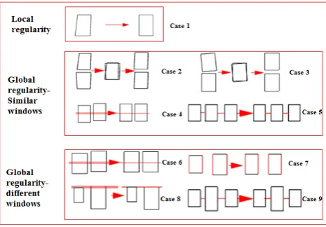
Regularities in a facade are contained either within one object or among many objects. As similar and different objects share many regularities respectively, regularities among objects are explored from similar objects and different objects separately. Therefore, the regularities are categorized into three types: local regularity within one window, global regularities among similar windows and global regularities among different windows. Nine common cases within the three categories and how the effects of method should be are shown in Figure 2. We define shape, orientation and position regularities in the second and third category according to the characteristics of different cases. Case 1: Boundary share orthogonal and parallel orientation. Case 2 (shape): Similar windows share same shape
Case 3 (orientation): Similar windows share same orientation Case 4 (position): Similar windows share same line alignment Case 5 (position): Similar windows share same distance Case 6 (orientation): Different windows share same orientation Case 7 (shape): Different windows share same length
Case 8 (position): Different windows share same line alignment Case 9 (position): Different windows share same distance
Figure 2. Nine common cases of regularities from three categories.
3.3 Principle of clustering for regularity
As shown in Figure 2, shared features are slightly distorted without significant distortion after automatic recognition. Clustering method can find similar objects in feature space. Therefore, the regularity can be identified from clusters. Weighted centers of clusters are chosen to calibrate all cluster members to share a regularity exactly. The hierarchical clustering method (Rokach and Maimon, 2005) is chosen for our research. Only one threshold needs to be specified to The International Archives of the Photogrammetry, Remote Sensing and Spatial Information Sciences, Volume XLI-B5, 2016
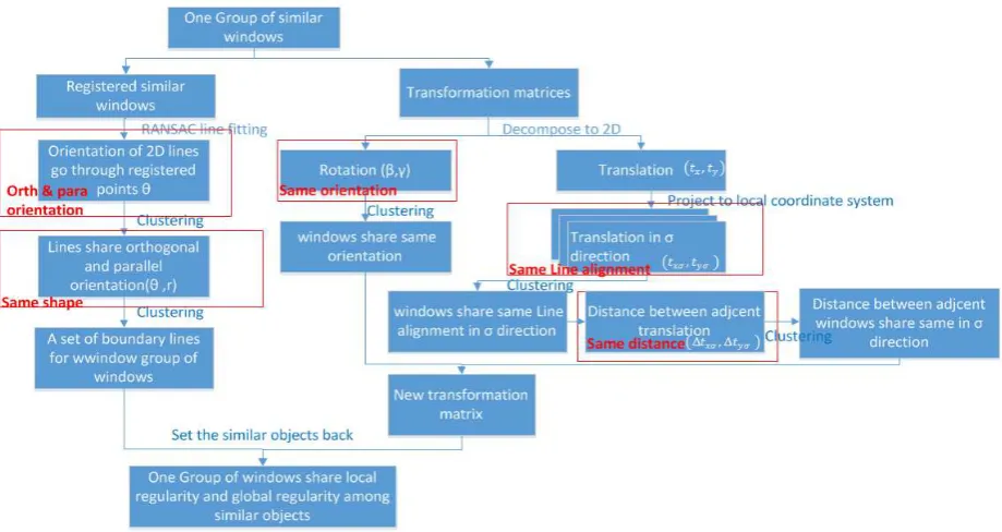
Figure 3. General procedure for regularity identification and application among similar windows.
Figure 4. Detailed procedure for regularity identification and application among similar windows. The red boxes show extracted features for corresponding regularization
determine where to cut the hierarchical tree constructed based on distance between objects. If the distances among objects are below the threshold, they fall into one cluster . In other words, it determines the extent of distortion to be accepted to share a regularity. As local regularity will be shared by similar windows, it is considered within the second category. Therefore, extracting features for regularity identification and application is split into two phases: among similar windows, and among different windows.
3.4 Regularity among similar windows
As shown in Figure 3, the first phase starts with ICP to extract iteratively different groups of similar windows. The window with highest density is employed as the target point cloud, while other windows are source point clouds to be registered with the target. The final average distance of closest pair between target and each of sources is to determine whether they are similar or not. Then from the remaining windows the one with the highest density is chosen for ICP, until no windows are left. One set of registered window points and several transformation matrices are derived from ICP for each group. As shown in Figure 7(a), all the windows are registered with the target in the left corner shown in a red box. Local regularity (Case1) and shape regularity (Case 2) are identified from registered window points, while orientation and position regularities (Case3-5) are identified from transformation matrices. The detailed procedure is shown in Figure 4.
3.4.1 Local regularity-Case 1: The RANSAC line-fitting algorithm that is resistant to noise is applied to find 3D boundary lines from registered points, as shown in Figure 7(b).
‘Local regularity’ means that boundary lines may share orthogonal and parallel orientation. The feature for presenting the orientation is required. To simplify the problem, the 3D lines are converted to 2D as all windows are in the same wall plane. The lines are presented in a polar coordinate system (θ, r) in order to reduce the dimensionality of features. The parallel and orthogonal orientations follow equation (1), (2) respectively.
� ≈ � ± 0, , (1)
� ≈ � ± , (2)
where �, �= orientations of two lines
As clustering can only identify similar objects in the feature space, the parallel and orthogonal orientations should be transformed according to the two equation. Then the lines that share local regularity are similar in θ feature space. A weighted center is chosen for each cluster. The orientations are transformed back through the equation and from the corresponding center. The result is shown in Figure 7 (c). The International Archives of the Photogrammetry, Remote Sensing and Spatial Information Sciences, Volume XLI-B5, 2016
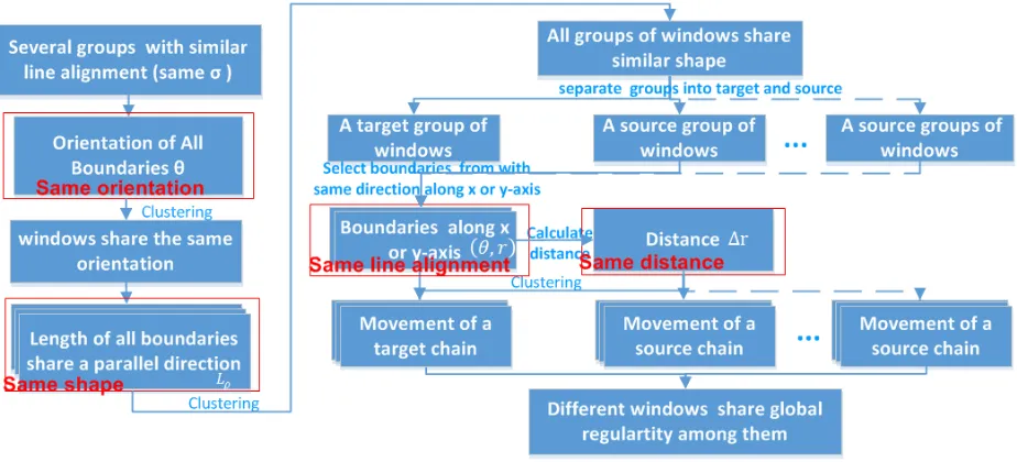
Figure 5. Detailed procedure for regularity identification and application among different windows. The red boxes show extracted features for corresponding regularization
3.4.2 Shape regularity-Case 2: ‘Shape regularity’ means that one set of boundary lines can be derived to present all objects. The clustering can find similar lines in two-dimensional feature space (r, θ). The centers of clusters give a set of boundary lines. The result is shown in Figure 7 (d) by four red lines.
3.4.3 Orientation regularity-Case 3: ‘Orientation
regularity’ means that the windows may share the same
orientation. A 3×3 rotation matrix is contained in the transformation matrix. As shown in Figure 7 (e), the windows have the same shape, but with original orientation information. Their orientation is little disordered, but in general they share a similar orientation. Due to the windows rotate on a vertical plane, the rotation in Z-axis is trivial and the orientation is
contributed by and in Y and X-axis respectively. The windows sharing the same orientation have the similar value in
( , ) feature space. As shown in Figure 7(f), the result is obtained by choosing weighted centers of clusters.
3.4.4 Position regularity-Case 4, 5: ‘Position regularity’ means regularities shared according to the position of windows , including same line alignment and same distance interval. A 3×1 translation matrix is contained in transformation matrix. The 3D translation can be reduced to 2D translation (� ,
� ) along the wall plane. If windows are aligned along the coordinate system defined by the wall as shown in upper two images of Figure 6, the similar translations of � or � indicate same line alignment. If they align along a line with a direction
σ, a new local coordinate system they aligned to can be identified by rotate original one with the angle as shown in bottom two images of Figure 6. σ can be derived by fitting lines to all translations (� , � ) and corresponding � � and � � are calculated. Windows with same line alignment have similar value in � � and � � feature space respectively. The distance,
∆� � and ∆� � between adjacent � � and � � are derived respectively. By clustering on ∆� � and ∆� �, same distances are obtained from cluster centers. The new � � and � � is recalculated and regularized to follow the two position regularities.
Figure 6. Upper two case: windows are aligned along the wall. Bottom two cases: windows are aligned in a new local
coordinate system.
3.5 Regularity among different windows
After applying regularities among similar windows in each group, the regularities among these different groups are considered. If windows from left two images of Figure 6 are in the same wall, the regularities between them is hardly to explore. In reality, the regularities are also not common between them. So the regularities in this phase are discussed within groups of windows with similar line alignment, σ. Although the regularities explored among same windows or different windows seem similar, the regularities in this section have their own characteristics. The detailed the procedure is shown in Figure 5.
3.5.1 Orientation regularity-Case 6: The regularity has the same meaning with that in section 3.4.3. However, the rotation matrices do not exist between different windows. We draw an assumption that if most of boundaries of windows share parallel and orthogonal orientations, they may share the same orientation. The same approach as in Section 3.4.1 is used. The result is shown in Figure 8(b).
Figure 7. First phase of regularization process for TN building facades. (a) the same type of windows are identified and registered to the targets window points. (b) RANSAC line-fitting is use to extract boundary lines from points. (c) Case 1: boundary lines share parallel and orthogonal orientation. (d) Case 2: one set of boundary lines (red lines) are chosen as the same shape (e) Set the windows
back with the same shape. (f) Case 3: Windows share the same orientation. (g) Case4, 5: Windows share the same line alignment and same distance.
Figure 8. Second phase of regularization process among different windows for BK building facades. (a) Four groups of windows after applying regularities within their group. (b) Case 6: the red highlighted window shares orientation with other windows. (c) Case
8: the red highlighted windows share same line alignment with adjacent windows. (d) Case 9: the red highlighted window share same distance with adjacent windows. (e) Final presentation of model after applying all regularities.
3.5.2 Shape regularity-Case 7: Instead of same shape shared among similar windows, the parallel boundary lines among different windows more likely share the same length. The boundaries with parallel directions, , are grouped and applied with clustering on ��. The new shape is updated with the regularized length.
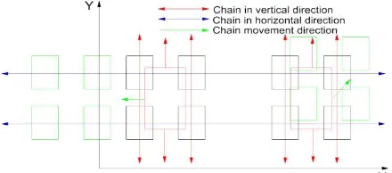
3.5.3 Position regularities-Case 8, 9: The regularities is similar with that in section 3.4.4. Except for the lack of translation information, there is one more tough problem need to be addressed. When applying position regularities, the positions of windows are shifted. However, when position regularities among similar windows are applied, the connections, called chains, established among similar windows should be preserved . As shown in Figure 9, a chain consists of connected windows (black) and a direction along X or Y axis. A chain shown as a line with arrow is due to same line alignment, while a chain shown as a rectangle with arrow is due to same distance.
Figure 9. The chains are established among similar windows and chains should move along X, Y-axis .
Therefore, two rules are defined: (1) if one window moves, the windows from the corresponding chain all should move. (2) the window can only move along the axes. First, if one window moves without considering chain, the regularized properties are broken. Second, if right four windows move to an arbitrary direction, shown as left four green windows in Figure 9, the established chains (blue) are broken. As position regularities can be only identified from boundaries instead of translation mactrices in Section 3.4.4, only boundaries along X, Y axis are chosen to confirm the second rule. Then, the line feature, (θ,r), of boundaries from different windows is chosen to identify the
same line alignment, while feature, ∆r, between adjcent lines
from different windows is chosen to identify the same distance regularity. To further simplying the problem by considering the The International Archives of the Photogrammetry, Remote Sensing and Spatial Information Sciences, Volume XLI-B5, 2016
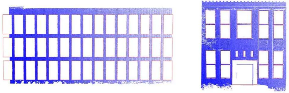
Figure 10. The results are overlaid with original wall points. Read lines are the results of model and blue points are points from original point clouds.
reality, the position regularities are explored among one group with most windows ( target group) and one of other groups(source groups) each time. The weighted averge movement is chosen for target windows in the end. The movement of other windows are recalculated accordingly. The result is shown in Figure 8(c), (d).
4. RESULTS AND ANALYSIS
In order to test the provided method, two point clouds are used: terrestrial LiDAR point cloud from faculty of Applied Sciences (TN), TU Delft, with only one type of windows; and terrestrial LiDAR point cloud from Faculty of Architecture and Built Environment (BK), TU Delft, with 4 types of windows. These point clouds are from Leica terrestrial LiDAR with 5cm density in average and 2 cm accuracy. The results are shown in Figure 7 and Figure 8.
Only Case 1-5 regularities are identified and applied in TN façade, as there is only one type of windows in the façade. For BK façade, the Case 1-5 regularities are applied with 4 types of windows and then Case 6-9 are applied among these different types. Both results show that the provided approach is effective to improve the quality of the model. However, even the results show the good regularization property, the correctness of these should be also verified. Therefore, the results are overlaid with their original point cloud of the wall. It is clear that the results shown as red lines fit original point clouds very well in general as shown in Figure 10. Instead of coincidence or luck, the good results is due to the clustering way for regularization identification. The threshold of clustering can control the extent of regularization in case of under or over-regularization. If the threshold is too small, the clustering cannot identify the regularities among windows with slightly difference; while too large, the differences in reality among windows may be regularized incorrectly. However, the thresholds can be set empirically from observations in reality, 0.05rad and 0.1m are chosen as thresholds related to orientation and distance respectively. These values work fine with common cases.
Still, there are also several thresholds need to specified. During the first phase among similar windows, there are two thresholds within ICP procedure: the numbers of iterations for registration and the average distances of closest pairs to determine the similarity. They are set to 20 times and 0,005m separately. The empirical thresholds performs well for 5 groups of similar windows (1 from TN, 4 from BK). RANSAC line-fitting algorithm also require two parameters: the distance to include
points to the estimated model and number of points required to define a valid line. As the weighted center is used for local and shape regularities share by these lines, the weight of each line should be defined. The weight is dependent on number of points the line goes through and where the points come from. If the points are from high density windows, they are given more weights. Therefore, the first parameter of RANSAC should not set too large. To the extreme case, if only one line are extracted for one boundary, the points contributes to lines equally. So it is better to choose a smaller value, such as 0.005m. However, if it is too small, the spurious lines are extracted. The second parameter is to limit these lines. If number of points is smaller than the total number of points/(4*20), the line is removed. 4 indicates around 4 boundary lines belonging to a window. 20 presents around 20 lines extracted for each boundary line. The spurious lines are also suppressed during clustering step. If a cluster only contains one element, it can be seen as the spurious line to be removed.
5. CONCLUSIONS AND RECOMMENDATIONS
In this paper, we explore regularities among windows to improve the quality of building reconstruction. The windows are the holes in the wall plane. So this paper is also applicable to the holes caused by balcony, intrusion, extrusions. The proposed approach subdivides common regularities systematically into three categories. The clustering approach is a very promising way to identify and apply regularity, as the only threshold, to what extent the slightly different objects can be included in the cluster, can be set properly and empirically to avoid under and over-regularization. The corresponding features for the specified regularities can be derived from provided two phases of regularity identification and application. The tested results show the good performance of our proposed approach.
There are still some limitations in our research, which require further research and development. Currently the research only explored regularities among holes in the wall. Other objects, such as intrusions and extrusions can be taken into consideration for regularities. For example, the boundary of a hole in the wall shared a boundary with doors. The intrusions may share a plane. That is why we always treat wall as 3D objects and features are converted from 3D from 2D instead of converting wall to 2D and extract 2D feature directly . These 3D features discussed in this paper are useful for this future research. After these regularities explored, the whole façade regularity exploration concludes. Moreover, many walls can be considered simultaneously. The regularities may also be The International Archives of the Photogrammetry, Remote Sensing and Spatial Information Sciences, Volume XLI-B5, 2016
extended to include many special cases. For example, orientations of similar objects are not the same, but share orthogonal orientations. The similar objects shares mirror reflection regularity. There are more special regularities we can imagine, but it would be better to include architects’ knowledge to define the suitable regularities in advance.
ACKNOWLEDGEMENTS
The authors would like to acknowledge Wuhan-Delft Joint Research Center and Universiteitsfonds Delft for supporting an exchange to Wuhan University, China. The authors also would like thank Cyclomedia, Inc, for supporting the research as an internship. Finally, the authors would like to thank Dr. Tingting Cui for the precious advices in Wuhan.
REFERENCES
Müller, P., Zeng, G., Wonka, P. and Van Gool, L., 2007. Image-based procedural modeling of facades. In: ACM Transactions on Graphics (TOG), 26(3), p. 85.
Pauly, M., Mitra, N. J., Wallner, J., Pottmann, H. and Guibas, L. J., 2008. Discovering structural regularity in 3D geometry. In: ACM transactions on graphics (TOG), 27(3), p. 43.
Pu, S. and Vosselman, G., 2009. Knowledge based reconstruction of building models from terrestrial laser scanning data. In: ISPRS Journal of Photogrammetry and Remote Sensing, 64(6), pp. 575-584.
Rokach, L. and Maimon, O., 2005. Clustering methods. In: Data Mining and Knowledge Discovery Handbook, Springer US, pp. 321-352.
Sampath, A. and Shan, J., 2007. Building boundary tracing and regularization from airborne LiDAR point clouds. In: Photogrammetric Engineering & Remote Sensing, 73(7), pp. 805-812.
Schnabel, R., Wahl, R. and Klein, R., 2007. Efficient RANSAC for point‐cloud shape detection. In: Computer Graphics Forum 26(2), pp. 214-226.
Xiong, X., Adan, A., Akinci, B. and Huber, D., 2013. Automatic creation of semantically rich 3D building models from laser scanner data. In: Automation in Construction, 31, 325-337.
Zheng, Q., Sharf, A., Wan, G., Li, Y., Mitra, N. J., Cohen-Or, D., and Chen, B., 2010. Non-local scan consolidation for 3D urban scenes. In: ACM Transactions on Graphics (TOG), 29(4), p. 94.
Zhou, Q.Y. and Neumann, U., 2008. Fast and extensible building modeling from airborne LiDAR data. In: Proceedings of the 16th ACM SIGSPATIAL International Conference on Advances in Geographic Information Systems, p. 7.
Zhou, Q. Y. and Neumann, U., 2012. 2.5 D building modeling by discovering global regularities. In: 2012 IEEE Conference on Computer Vision and Pattern Recognition (CVPR), pp. 326-333.