MODELLING AND ACCURACY IN A BIM ENVIRONMENT FOR PLANNED
CONSERVATION: THE APARTMENT OF TROIA OF GIULIO ROMANO
A. Adami
a, B. Scala
a, A. Spezzoni
aa
Politecnico di Milano, Polo di Mantova, Dept. ABC, Piazza d’Arco, 4, Mantova
[email protected]; [email protected], [email protected]
Commission II
KEY WORDS: BIM, accuracy, 3D modelling, HBIM, planned conservation, restoration
ABSTRACT:
Modeling of Cultural Heritage in a BIM environment, and in general of existing buildings, requires special attention because there are two diametrically opposed possibilities. On the one hand the attempt is to realize a very complex and accurate model, in order to provide the most comprehensive representation of the architecture as possible. The opposite position leads to build a very schematic and symbolic model of as-built architecture. It is not easy to determine which is the right balance between these two attitudes because each architecture requires a personalized approach and not standards. It’s, however, necessary to find rules to figure out which items are represented, what is the minimum level of detail to consider adequate and how to deal with alterations from simple and linear geometries.
These two facing possibilities deal with different goals and tools. In the field of restoration or planned conservation, that is the most common approach for existing buildings, the attention focuses on the exceptions and particularities of each architecture: the important aspect is to understand and describe exactly each part as a singularity (as it is). In this context it is very difficult to find a standard or a common solution.
The first possibility of modelling seems to be very close to this approach, but it clashes with two important aspects. A first problem concerns the modelling software. Usually commercial BIM modelling software doesn’t allow to realize very complex and high detailed solutions. They prefer working with predefined families and try to categorize each element in standard solution. The possibility to build new families is expected, but it often requires a lot of time. The second difficulty is the real efficiency of such an accurate model. In fact, it could be very difficult to link external elements to the model or use it in many traditional BIM applications.
In this paper, we suggest another possible approach that represents the first result of a research about the modelling of Cultural Heritage for BIM application. The proposed solution aims to give as much information as possible about the architecture, and, at the same time, to guarantee a higher efficiency. In this case we considered commercial BIM software like Revit or Archicad. They are the most widespread and well-known software BIM oriented and they also allow the use of their embedded database structure. The core of our solution is to describe the architecture not only by a 3D model but also by the representation of the reliability of the accuracy of the model itself. In this way we try to combine the necessity of working with commercial software, in which it is difficult to be very accurate, and the information about the real object. In historical complex architecture, for example, it is very difficult to find a straight and planar wall. It is quite difficult, or at least time consuming, to model that kind of wall with high accuracy. But it is possible to represent the real wall by a schematic wall with a false color map which describes where the 3D model is well fitting and where there are some differences. In this way we don’t lose any information but, at the same time, we have a very usable BIM model.
1. INTRODUCTION 1.1 BIM for Cultural Heritage
The use of BIM for Cultural Heritage is the new goal for a discipline, the restoration, which is, by itself, very conservative and connected with traditions. Many researches in Italy (BHIMM, 2014) and other countries tried to suggest some approaches to this challenge and gave their solutions which put in evidence potentialities and difficulties. From the beginning, it was evident that it would be difficult to combine an approach based on standardization with the historical reality, which is made of unique elements (Bolgarino 2014).
This paper describes the ongoing experience in Palazzo Ducale di Mantova where BIM has been selected as the tool for the planned conservation of the apartment of Troia. This choice confirms the potentiality of BIM for planned conservation as concerning, in particular, the common practice of decomposing the architecture in its single element and categorize them in a “work breakdown structure”. It allows the complex
management of the conservative process.
The core of this research is the construction of a model suitable for the planned conservation and the management of the architecture. The 3D, in fact, is always the result of a design stage of the model itself and of many other aspects which contribute to the specificity such as the accuracy of modelling, the geometrical complexity of architecture together with the advantages and problems of commercial BIM software like Revit or Archicad. But we have to consider also other elements to define the best solution: the possibility to obtain, for each element, the most appropriate representation, the interoperability of software, the use of plugins to link the model with the database.
1.2 ICT and the conservative process
The use of BIM-oriented modeling shows great potential: the model is the document manager for the collection of the whole information system, for the coordination of all documentation related to the design phase, construction and execution. These
features help to ensure coordination between the various figures involved during the building process. Delivering these capabilities to the field of the existing building, we can see that the application of Building Information Model for the knowledge and management of the architecture has some significant advantages, joined with some operative and conceptual difficulties.
At first, a model designed according BIM criteria allows you to collect different kind of data in a single database: drawings and historical maps, documentation of archives concerning the evolution of the artifact, its material and typological characterization, CAD drawings related to more or less recent surveys.
The model is also an excellent knowledge tool and basic element for further investigation and tests, made by experts in the field (such as diagnostic analysis which could be useful to define the conservation works or restoration projects or an appropriate conservation program on the building over time). In addition, the BIM model is potentially interoperable with different energy simulation or structural analysis. This allows you to face two particularly significant issues in respect of existing buildings. An energy simulator permits to perform analysis on the efficiency of the article, in terms of management costs and, on the other hand, it allows us to estimate potential savings of energy and costs by directing an intervention. Similarly, the insertion of the model in a structural calculation software provides information on the state of conservation of the building and it allows to make projections on its behavior in the short and in the long period, with or without consolidating interventions.
It is not excluded that in case the historical heritage is now used as a museum, it is possible to think that BIM model could be used for educational purpose. It could be a 3D that gives a general idea of the museum complex you are visiting, or, more specifically, to illustrate for each element molded material, construction characteristics and period of construction, to give an overall picture of the building evolution over time. Moreover, from the point of view of the administrative goals, a BIM oriented model can facilitate the management of the building, ensuring the ability to manage within the model itself documents related to security, such as evacuation plans, or management costs and plans and maintenance.
Among the negative aspects emerged with the approach to the built standardizing systems, one of the most important regards the difficulties linked to the recognition of the uniqueness of each component which becomes more or less complex to manage in relation to the different weight of witnesses who recognized the historical reality and the meanings attributed to it in different cultural contexts.
The large bibliography of recent editors highlights the broad interest in the subject, the multiple forms assumed by the research, the vast fields of experimentation, as well as more or less satisfactory results (Babetto, 2014) (Barazzetti, 2015). It is interesting to see how the use of BIM tool goes along with the need to overcome the two-dimensional vision with which it has always proceeded in the investigation of historical heritage. A shared 3D representation of historical buildings provides a unique reading and subsidiary of construction problems and gives the possibility of being informed about nowadays situation and the future one, by projecting and verifying the results in a predictive manner of possible actions to take or to be given up.
The 3D modelling is also a problematic element in the pipeline of BIM as it requires a lot of time to obtain a good model (Quattrini, 2015). But, moreover, the level of accuracy of 3D model is not a completely solved question. Many institutions
tried to give a solution, by using some guidelines or regulations, but they are directed above all on standard BIM application where the object is the result of a new design concept and not the last point of an historical process (COBIM, 2012) (Statsbygg, 2013).
The dynamism of the BIM brought good results in the occasion of studies on historical buildings, when they are in a situation of risk of loss not only material but also intangible one. In fact, the comparison of different construction stages, witnessed by archival documentation, has found an effective identity within digital archives, in which the reproduction of historical phases has clarified doubts and ambiguities found in the process of reading the documentation. In this field there are many experiences of archaeological type, where BIM is a tool to reconstruct the successive transformations of buildings (Carrara, 2014)
In the urban field, the model of historical buildings was compared with the transformed urban context, in various historical thresholds, not only to understand why, for example, these contexts were abandoned, but also to assess lines of promotion, incentives to reuse and development of historical settlements uninhabited or so that use.
Many BIM applications were developed with the goal of understanding the transformation that any building actions may introduce in the historical buildings. They previously assess the implications as a result of building installations, adaptations to improve accessibility for the disabled, as well as the distribution of furnishings internal (meaning as furnishings also non-structural partitions needed for better organization of internal space in relation to the intended use) or urban (Fai, 2011) (Fai, 2013).
From the analyzed experiences it is evident how often the BIM is considered an instrument similar to AUTOCAD but with the additional option to "show a 3D" system that normally ensures greater harmony in the representation, more readable and reliable, opening a direct dialogue on the object drawn. But we cannot forget how BIM is not just a software to draw but it is a tool for the management of the entire supply chain of the historic building.
In the light of what said, the next step of the research is to direct the instrument towards greater flexibility, often made difficult by the long graphics processing in which the model needs to ensure to keep the integrated information, and recognize each element as unique and unrepeatable. There are many schedules of historical construction elements produced and shared but, if we want to consider them as "intermediary" for a proactive operation, it is necessary a better validation of the same, focusing on the need for graphical accuracy, identifying the quality, quantity and organization of information to complex management.
In the field of geomatics, the interest for a more in-depth detail level has led to the development of techniques and methods based on photogrammetric and laser scanning approaches and to obtain data with increasing accuracy. The solution of decreasing the accuracy of the modelling does not seem to be satisfactory as it could frustrate all the work for implementation in the survey phase, and on the other hand, there is a risk of losing information that may be fundamental in the analysis of the artefact, with particular reference to all the deformations which could be symptomatic of structural problems which could need an intervention. If we will use standard walls, all that information will be lost, compromising the usefulness of BIM.
On the contrary, wanting to make the model as close as possible to reality and, at the same time, as functional as possible according to a BIM approach, the solution would be to create
new ad hoc libraries for individual model objects. But in this case it requires a highly specialized type of user, with a more designer approach that mere modeler and also a lot of time. To facilitate this task, the producers of BIM commercial software in the last years seem to have been sensitized to the issue of hand construction of new types of parametric objects and have introduced the ability to import point cloud modeling in the environment even if their use in modeling still has some problems (figure 1). In fact, the inclusion of dense cloud makes the navigation more difficult and complicate the modeling phases. In addition, the actual opportunity to interact with the cloud of points remains inadequate since it does not work the snap to the cloud points, less than insert in the plug-ins program.
In order to solve these problems, especially the ones related to the accuracy and level of detail of final model, we suggested a possible solution to make the user of BIM model as much as possible conscious of the properties of the model and of the choices made by the constructor of the model. This could answer also to the fact that each kind of intervention on existing building needs different requirements: a restoration intervention needs a more precise model than planned conservation, where the model works above all as a 3D index of single elements. It should be pointed out, finally, that in order to maximize the potential of the BIM model is necessary that each architectural element corresponds to a parametric object of the same typological characterization (masonry must be elements of wall type and not conceptual mass or generic models) since otherwise it would lose the opportunity attribute parameters, and therefore information, to objects.
1.3 The apartment of Troia, by Giulio Romano
The apartment of Troia is a portion of the work of Giulio Romano inside the Palazzo Ducale di Mantova, built on the main floor between 1536 and 1539, the Federico Gonzaga court. The apartment consists of several rooms: the sala dei Cavalli with loggia and Cortile dei Cani, the Camerino dei Falconni, the sala delle Teste, with the Camerino dei Cesari, the Sala di troia and the Loggia dei Marmi (Berzaghi, 2014). A large part of the sumptuous apartment of Troia decoration unfortunately disappeared, despite large recoveries of the early twentieth century.
For the Sala di Troia, analyzed in this article, Giulio Romano conceives an extremely dynamic composition and illusionistic that fuses wall – where there are distinct episodes - and ceiling - where, however, the battle appears to be continuous - exploiting the visual trick of the trees that get up in the four corners of the ceiling connecting the scenes. The execution is much lower than the generality of the idea of human and animal figures that "turn and twist in space" toward and away enough to create a three-dimensional effect. In fact, he didn’t work directly on this room, and the decoration was left to disciples whom the teacher says dissatisfied. Under the vault of the rectangular room a narrow ledge of gilded stucco turns all around the room. Also the paintings of the walls are divided into panels that are surrounded by similar golden trim package. The room is painted in big scenes from the war of Troia. This illusionistic ceiling fresco became, especially in the Baroque period, the model for countless similar decorations (Regozzino, 2003).
2. MODELLING METHODS
Modelling with Revit (release Revit 2016) is generally considered a fast solution for new constructions, because the
software offers simple and quick methods to model. However, these methods have some limitations to model an existing building, starting from laser scanner survey data (importing point cloud by Recap). So it was necessary a first stage of study and research in order to explore possible techniques and to decide which ones were practicable and BIM-oriented. In fact, they had to allow to create models as close as possible to the reality in quite short time and, at the same time, to guarantee the full functionality typical of a BIM model.
The following paragraphs show methods that, among various attempt explored, can be considered the more suitable ones, each one coming from the idea to explore and re-elaborate one or more modelling techniques offered by Revit in order to reach the best compromise between BIM-oriented model and the survey data acquired.
Before starting the modelling phase, it was necessary to define how to break up the architecture into different and small elements. The choice was made by considering the classification used in restoration for architectural elements. The codification is composed by six shared parameters (Vandesante, 2015) (Della Torre, 2014a, b) and, on the whole, they categorize all the elements in a hierarchical classification that takes into consideration the technological element, the architectural one, the position and a sequence numeration. The use of shared parameters to qualify the element was opted because it is the only type of parameters that can be included in schedule, useful to manage the model. In fact, the schedule of elements represents a list of all object belonging to the same family and can be customized to show and modify features (parameters) of them.
2.1 Survey data
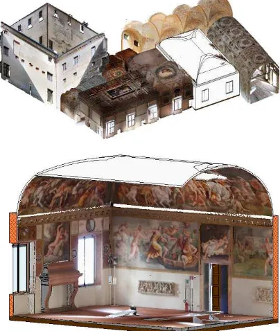
To realize the BIM model, it was not necessary to do a survey campaign as the Politecnico di Milano, in 2009-2010 surveyed all the apartment (Figure 1).
The reuse of data allowed to eliminate the time for survey and start directly with the set-up of the modelling.
Figure 1: (top) the 3D model of Sala di Troia with all the point clouds of Apartment di Troia, (bottom) point cloud integrated in Revit environment.
The rooms were surveyed by laser scanner (Leica HDS 7000) and the scans were georeferenced in a single reference system on the basis of a topographic survey. Usually each room was acquired with only one scan (apart from the most complex Sala dei Cavalli and Sala di Troia) and the resolution was about 5 mm (40 million of point for each room). In the same campaign, also color information was acquired. After laser scanner acquisition, from the same position of the instrument, a panoramic image was acquired with fisheye lenses in order to texture the point cloud. The color resolution is not very high, so the RGB value can be used only for a simple description of space and decoration and not to obtain orthophotos.
2.2 Wall and wallcovering
The first step to define the object of study is to create the walls that enclose the space of the Sala di Troia.
In Revit, the family wall allows to create different type of objects defined by base constraint, height and the layer structure, and relative thickness, but unfortunately, in the modelling phase, it’s possible to personalize the direction of the element only on the horizontal plane and not on the vertical one (off plumb walls). To solve this problem, it could be possible to divide the whole element in more sub-elements with different thickness but, the result could lose continuity and introduce gaps between consecutive elements, intolerable and unpleasant because they don’t really exist.
On the other hand, it’s impossible to exclude completely the use of the family wall, in fact, they have to be employed at least for the general trend of the architectural element because without walls the model misses host for family wall based, like windows and doors.
So, the wall, modelled with direction and thickness completely included between the surveyed surface, both in the vertical and horizontal sections, represent the core structure of the element and then, from the outside, it has to be covered by another element modelled to bridge the gap between the surface of the wall and the survey data.
The first idea to realize this last element is to create a new family of adaptive column because it can be fuse together with the wall and it can be customized in order to hang out up to the laser data. This solution seemed complex because the adaptability of the family consists in manually attribute the position of each vertex of the column, in function of the distance between the center line of the wall and the point of the laser data standing for the real surface of the wall.
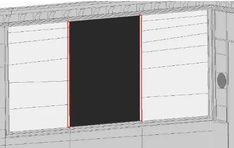
Rejected this method because of both functional and temporal aspects, the preferred solution consists on the creation of a model in-place as a wall family. The great flexibility of local modelling reveal itself useful to create models closer to the reality, thanks to the possibilities to model with extrusion or sweep, bend or swept bend, revolve around an axis of profiles designed ad hoc in compliance with laser data; each method permits to create a solid or void element. In case of wallcovering it was advantageous to model with swept blend, in which the first and the second profile are designed following the vertical section of the point cloud and the distance between them suit the evolution of the wall surveyed (Figure 2). Moreover, this method reproduces the same classification used in restoration where the structural part of wall is separated from the superficial finishing.
At this step, it arises a problem on the range of error that could be considered tolerable for an element. As it is a controversial choice, mainly based on the following use of the model, in this study case it was decided to limit the error on the range of some centimeters, because on the one hand for this particular object
this range results sufficient to create a model close to reality and, on the other hand, it avoids a useless waste of time on modelling.
In order to draw the profiles for the swept bend, two methods were tested: the first one, mainly used for large surfaces, consists on an intermediate step developed in AutoCAD software to extract the profiles, because the possibility to set up cut planes to slice the cloud and work planes to draw helps a better control on the resulting profile drown; the second one, consists on the use of the section box in order to section and reshape the point cloud, however without a full control of the plan on which the cloud is projected and drown, and it was used for small objects or to adjust profiles that, even if they were drown in adherence to the laser data, they involved a model not completely satisfying.
Figure 2: detail of the modelling of the wall and wallcovering. The dark grey represents the wall, the lighter grey the wallcovering. The red sections are extracted from point cloud and used for swept bend.
2.3 Doors and Windows
For doors and windows, we created ad hoc families that could portray a shape closer to the real one. The method is the same for new or existing buildings but, in this case, the object to model cannot be standardize and, as a consequence, the number of parameters to describe it increase in order to suit better the element to equivalent real one.
In particular, parametric profiles like wood frames and glass or wood panels, were created to model all the elements of the window and the doors, and they were nested inside relative families. Finally, we also modelled parametric void shape useful to recreate, and customize, the splay, typical for historical buildings like Palazzo Ducale.
At the insertion of doors and windows, each instance is positioned and adjusted in its parameters to adapt to the point cloud. It’s important to say that doors and windows are wall based families that can be hosted on a wall object but they can’t interact with model in-place that cover them so that, for example, a wall is pierced by the window and its splay, but the wallcovering remain complete. This last one element needs to be manually modify by the creation of a void element that retraces exactly the splay.
2.4 Decorations
Wall surfaces present low-relief, moldings that frame fresco surfaces from plaster ones and spherical cap recesses.
Low-relief were modelled with the same method used for wallcoverings.
For moldings, the adopted solution was to create a swept bend
in a model in-place, drawing profiles with a unique general shape, and adapted, time by time, to get a profile close to the point cloud.
Finally, for the spherical cap recesses, considering them related to the same frame, it was decided to realize a specific family, as a generic model wall based, and attribute it parameters of diameter, depth and distance of its external surface from the wall. At the moment of their insertion in the project, it was possible to define these parameters to suit the element to the reality. As it was for doors and windows, this type of family doesn’t interact with model in-place created for wallcoverings so that also in this case they had to be modified manually with a void element retracing the recesses.
2.5 Horizontal closures
The floor of the study case is not a plane; in fact the point cloud shows there are different distances from an ideal horizontal plan. To solve this problem, it was opted to create a floor element, representing the structural part of the architectural element, simplified to a perfect horizontal plane, and a second floor element, representing the finishing layer, modelled whit a variable section, on which there were identified control points whose elevation could be modified to fit the element to the laser data.
For the ceiling of the object of study, characterized by a cloister vault, different techniques were tested. The first hypothesis was to create a new type of ceiling with a thickness large enough to contain the entire depth of the vault, from which it could be subtract an adaptive model constituted by a void form modelled with a sweep of a curved profile. Unfortunately, the resulting element was not satisfying because it was too much regular and different compared with the real one.
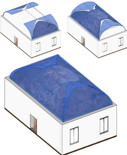
Figure 3: Vault construction by successive subtraction of solids.
The second attempt concerned the creation of the inner surface of the vault in Rhinoceros (NetworkSurface), to export as mesh and import in a new conceptual mass in order to model the
negative shape of the vault. Finally, using the function ceiling by surface, it would be possible to model a vault exactly with the shape created in Rhino.
This method resulted a failure because the software was not able to elaborate the surface to a conceptual mass. Rejected both these options, the adopted solution was to create a ceiling as model in-place as roof: this was modelled with three swept bend elements (one for the longitudinal direction and two for the transverse one), using profiles drown in adherence to the laser data, and three connected void elements to cut the protruding part towards the vault (Figure 3).
2.6 Data organization
As the modelling stage started from the breakdown of the whole architecture in single elements, on the basis of the codification used in restoration, the structure of the model reflects the same subdivision. In this way, Revit allows to extract automatically a schedule which uses the same subdivision of the model. And moreover we can establish a direct connection between the 3D model and its schedule. We can add information to each element through the property windows of the element or the single record in the schedule. This aspect, even if built automatically in Revit, allow the restorer to add information about materials, conservation to the model using a well-known structure (Figure 4).
Figure 4: schedule and view of the model. The same element is selected in the schedule and in the model.
The proposal grammar for the modelling, adhering to the approach of BIM modelling, i.e. the representation of architecture organized for technological elements (walls, windows, frames etc.) and not architectural, supports the procedures of management of the planned conservation. Indeed, it starts from identifying technological elements whose uniqueness is given by the assignment of an identification code. In the present case the codes for example SvMp, IniFe, AdeCo, etc. not only identify the object referred to give, for example, conservative requirements but also identify the modelled element with a bi-univocal correspondence.
This direct feedback exceeds the drawing gap in CAD environment in which the construction element was identified in two dimensions from a closed polyline connected to a written code and the only possibility was to manage the whole draw with the particular inside.
The needs of the planned conservation find in BIM an organized tool of management, in which the geometric accuracy (which maintains its value and therefore the end purposes) share its role with the correct individuation, by topology, of all elements. In other words, the BIM for the planned conservation is a tool that, by identifying uniquely a technological element and sharing information with operators (designers, restorers DL, etc.) allows to act more directly on the problem and with less
dispersion of forces. In our case, if, for example, a window shows some leaks (for example, emerged from a thermal efficient investigation) different from the other windows, the repair will not be performed cumulatively and undifferentiated. Specific prescription will be given to the first and a more expeditious control for the second. Similarly, for a painted surface identified in the database related to the model with ADiAf 105_5 (fresco decorations, first floor, room 5, fresco 5), the design operations or inspection requirements will affect only an identified portion with diseases or conservative situations not necessarily identical to those of the other frescoed surfaces.
The greater specificity of action on individual technological elements, briefly illustrated here, has as its counterpoint the opportunity also to standardize the prescription for shared actions of all the technological elements of the same type. For example, the control of fire sensors will be held, probably in every room, with same conditions and with equal times. So when the inspector will verify all the sensors, he will compile the results of the one identified with IMAiSe 105-1 (fire sensor system, first floor, room 5, sensor 1) and at the same time, if there were no problems, everyone will have positive inspection. Or in case of its restorative activities, he will keep the memory of his action not only within the invoice, but also in the database.
3. DATA VALIDATION AND ACCURACY ASSESSMENT
At the end of the modelling stage, the problem was to validate the process and, above all, to give the user some information about the model trustworthiness. We chose to compare the results of modelling with source data.
The comparison was quite simple, as the model was built on the original coordinate system of laser scanner data. Without considering the decorative elements such as some niches and low-reliefs, the model was imported in cloud compare and compared with the original point cloud of the room. The comparison was made as a difference between the pointcloud and the surface, and the results were represented by a false color which describes the distances.
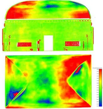
The results of the comparison can be given to the user in two different ways. The simplest way is to link a false color map to the wall (or surface to be compared). So the restorer or the architect had simply to open a jpg file and discover if the model he is using is well fitting to real data (Figure 5).
As said before, it is very difficult to define a limited range of admitted errors: it depends on the characteristics of the architecture, the quality of initial data, the use of BIM for an architectural intervention or only as a 3D index for management and planned conservation purposes. By giving the user an information about the quality, the user himself can decide if the accuracy is enough or it is necessary to improve the model. The other possibility of representation is to view directly in real time the result of comparison. It is enough that Cloud-compare converts scalar fields (distances) into RGB values and export them as the traditional colors of a point cloud. Than point cloud can be indexed in Recap and then imported in Revit where it can be viewed directly in the model. At this point the visualization, even if simple, is very clear and each element can be investigated in terms of true level of modelling and accuracy.
Figure 5: map of model accuracy of different part of the room. On the top a façade, on the bottom a top view of the vault. As evident the biggest modelling errors are in the vault, while in the facades the red parts correspond to decorative elements.
Compared to the single views externally linked to the model, the interactive visualization of the point cloud allows to have information also about 3D objects (Figure 6).
Figure 6: Axonometric view with the point cloud of geometric model accuracy
4. CONCLUSIONS
The use of BIM for Cultural Heritage is the new goal for the disciplines which works on existing heritage, but, in spite of a big effort of many research groups, there is still no a final, unique and shared, solution. In this context the first results of this research can help to find a solution.
A first assumption is the necessity of a modelling stage which is based on a work breakdown structure. The subdivision in small elements of the main architecture has to be connected with the aim of the BIM. The subdivision that takes into account the
structural, architectural and decorative elements seems to be very reasonable, as it is also suitable for tridimensional analysis and not only 2D. Moreover, it represents the way all data will be accessed during the management of the architecture, so it helps the further steps of the BIM process (data entry, updates, etc.).
Another suggestion from this work regards the big problem of model accuracy. As we saw, there are many approaches and each one can have positive or negative aspects. The real nature of the restoration would lean toward a very accurate representation of architecture. Nevertheless, the problems related to the required accuracy level remain open. Waiting to find a solution, which allows to clearly define what is the expected precision in the 3D model for the BIM, our proposal is to inform the end user about the quality of the model. In this way the restorer, who will work directly with BIM application, will be able to evaluate if the model is suitable for his purposes or if it will be necessary a more detailed model (and exactly where).
This solution is not a way or an expedient not to solve the main problem. It is a temporary answer to the problem of find a solution as universal as possible in a context where each architecture is unique.
The next steps of this research will investigate the level of detail concept applied in the restoration field and the opportunity of using a single, high resolution, model or many models, each one specifically suited for a goal but all georeferenced and linked in the same BIM.
ACKNOWLEDGEMENTS (OPTIONAL)
Special thanks to the architect Antonio Mazzeri of Palazzo Ducale, for allowing the access to the Apartment of Troia and having shared the BIM design process.
REFERENCES
Babbetto, R., 2014: The use of Building Information Modelling for the Planned Conservation of the Built Heritage: Methodological and Operative Issues. Archi-DOCT, Vol. 2, pp- 28-38, available at: www.enhsa.net/archidoc.
Barazzetti L, Brumana R., Banfi F., Lostaffa F, Piraino F, Previtali M., Oreni D., Fabio Roncoroni, Villa L, 2015: BHIMM e Augmented Information: il rilievo per la conoscenza e la valorizzazione di Castel Masegra. Proceedings of XIX Conferenza Nazionale ASITA, 29-30 September - 1 October 2015, Lecco - Polo di Lecco of Politecnico di Milano, 2015.
Berzaghi R., 2014: L'appartamento di Troia. Giulio Romano. Palazzo Ducale, in La Reggia, Mantova, 2014, XXIII, p. 19, n. 3 (89) pp 5-8.
BHIMM, 2014, PRIN 2010-2011 - prot. 20104TA4Y8, http://www.abc.polimi.it/fileadmin/abc/images/news/BHIMM.p df
Bolgarino M.P., Della Torre S., 2014: Planet Beni Architettonici. Uno strumento per la conservazione programmata del patrimonio storico-architettonco. ICT per il miglioramento del processo conservativo, atti del convegno, International Conference Preventive and Planned Conservation, At Monza - Mantova, Volume: 5, Nardini, Firenze, pp 13-29. Carrara G., Simeone D., Cursi S., 2014: Bim and Knowleged management for building heritage. (edited by) David Gerber,
Acadia 2014 Design Agency: Proceedings of the 34th Annual Conference of the Association Computer-Aided Design in Architecture, Los Angeles, California, 23-25/10/2014, Brighton pp 681-690.
COBIM, 2012, Common BIM Requirements COBIM 2012, Series 2, Modelling of the starting situation, p.10 , available at https://asiakas.kotisivukone.com/files/en.buildingsmart.kotisivu kone.com/COBIM2012/cobim_2_inventory_bim_v1.pdf Della Torre S., (edited by) 2014:, La Conservazione Programmata del Patrimonio Storico Architettonico: linee guida per il piano di conservazione e consuntivo scientifico. Milano, Guerini, 2003.
Della Torre S., (edited by) 2014:, Oltre il restauro, Oltre la manutenzione. La strategia della Conservazione programmata Dalla progettazione delle attività alla valutazione degli impatti, Nardini Editore, Firenze 2014.
Fai, K. Graham, T. Duckworth, N Wood, R. Attar, 2011: Building information modelling and heritage documentation. 18th International Conference on Virtual Systems and Multimedia. XXIII CIPA Symposium – Prague, Czech Republic.
Fai, Filippi M., Paliaga S., 2013: Parametric modelling (BIM) for the documentation of vernacular construction methods: a Bim for the commissariat building. ISPRS Annals of the Photogrammetry, Remote Sensing and Spatial Information Sciences, Volume II-5/W1, 2013 XXIV International CIPA Symposium.
Quattrini R., Malinverni E. S., Clini P., Nespeca R., and Orlietti E., 2015: From TLS to HBIM. High quality semantically-aware 3D modeling of complex architecture. Int. Arch. Photogramm. Remote Sens. Spatial Inf. Sci., XL-5-W4, 367-374, doi:10.5194/isprsarchives-XL-5-W4-367-2015, 2015. Ragozzino M., 2003: Le imprese decorative di Federico II. (edited by G. Algeri) Il Palazzo Ducale di Mantova, Sometti, Mantova, 2003, pp. 151-182.
Simeone D., Cursi S., Toldo I. and Carrara G, 2014: B(H)IM - Built Heritage Information Modelling - Extending BIM approach to historical and archaeological heritage representation. Thompson, Emine Mine (ed.), Fusion - Proceedings of the 32nd eCAADe Conference - Volume 1, Department of Architecture and Built Environment, Faculty of Engineering and Environment, Newcastle upon Tyne, England, UK, 10-12 September 2014, pp. 613-622.
Statsbygg, 2013: BIM Manual 1.2.1, Statsbygg Building Information Modelling Manual Version 1.2.1 (SBM1.2.1) – Date: 2013-12-17, Oslo, Norway available at http://www.statsbygg.no/Files/publikasjoner/manualer/Statsbyg gBIM-manual-ver1-2-1eng-2013-12-17.pdf
Vandesande A., Van Balen K., Della Torre S., Moioli R., 2015: A preventive and Planned Conservation strategy aimed at sustainable development. 18th ICOMOS General Assembly, Heritage and Landscape as Human Values, Theme 4 Community-driven conservation and local empowerment M. Di Stefano (edited by), Firenze 9-14 November 2014, ICOMOS, 2015, pp. 480-484.